Page 3573 of 4770
CYLINDER HEAD
EM±67
1353 Author�: Date�:
(b) Connect the fuel inlet hose to the fuel filter.
CAUTI")
S04791
8 mm Hexagon
Wrench
S04790
Chamber Stay
Engine
Hanger EGR
Pipe
± ENGINE MECHANICAL (1MZ±FE)CYLINDER HEAD
EM±67
1353 Author�: Date�:
(b) Connect the fuel inlet hose to the fuel filter.
CAUTION:
Perform connecting operations of the fuel tube connector
(quick type) after observing the precaution.
(See page SF±1)
(c) Connect the heater hose to the intake manifold.
29. RETIGHTEN WATER OUTLET MOUNTING BOLTS
AND NUTS
Tighten the 2 bolts and 2 nuts.
Torque: 15 N´m (150 kgf´cm, 11 ft´lbf)
30. INSTALL AIR INTAKE CHAMBER ASSEMBLY
(a) Using an 8 mm hexagon wrench, install a new gasket and
the air intake chamber assembly with the 2 bolts and 2
nuts. Uniformly tighten the bolts and nuts in several
passes.
Torque: 43 N´m (440 kgf´cm, 32 ft´lbf)
(b) Install 2 new gaskets and No.2 EGR pipe with the 4 nuts.
Torque: 12 N´m (120 kgf´cm, 9 ft´lbf)
(c) Install the No.1 engine hanger with the 2 bolts.
Torque: 39 N´m (400 kgf´cm, 29 ft´lbf)
(d) Install the air intake chamber stay with the 2 bolts.
Torque: 19.5 N´m (200 kgf´cm, 14 ft´lbf)
(e) Connect the PCV hose to the PCV valve on the RH cylin-
der head.
(f) Connect the ground strap and cable to the intake air con-
trol valve for the ACIS.
(g) Connect the ground cable and strap with the nut.
Torque: 14.5 N´m (145 kgf´cm, 10 ft´lbf)
(h) Connect the ground cable to the air intake chamber.
(i) Connect the brake booster vacuum hose to the air intake
chamber.
(j) Connect the 2 water bypass hoses to the throttle body.
(k) Connect the air assist hose to the throttle body.
(l) Connect the purge hose to the emission control valve set.
(m) Connect the 2 vacuum hoses to the vacuum tank for the
ACIS.
(n) Connect the engine wire clamp to the emission control
valve set.
(o) Install the PS pressure tube with the 2 nuts.
(p) Connect the throttle position sensor connector.
(q) Connect the IAC valve connector.
(r) Connect the EGR gas temperature sensor connector.
(s) Connect the EGR valve position sensor connector.
(t) Connect the VSV connector for the ACIS.
(u) Connect the VSV connecter for the EVAP.
(v) Connect the VSV connector for the EGR.
Page 3587 of 4770

No.2 Idler Pulley Bracket
Water Seal Plate
Engine Cool")
EM050±03
A06640
Knock Sensor Connector
Engine Wire Band
Engine WireKnock Sensor
No.2 ECT Switch Connector
Water Inlet Housing
(With Water Inlet)
No.2 Idler Pulley Bracket
Water Seal Plate
Engine Coolant
Drain Union
Oil Filter Union
Oil Filter � Gasket
EGR Cooler
� Gasket
Water Pump
� Crankshaft
Front Oil Seal
Crankshaft
Position Sensor
Connector� Oil Pressure Switch
Oil Pressure Switch
ConnectorA/C Compressor
Housing Bracket
No.1 Oil Pan
x 15 or 17 Oil Pump
� Gasket
� Gasket
Engine Wire
Generator
Drain Plugx 10No.2 Oil Pan Oil Strainer
� Non±reusable part
N´m (kgf´cm, ft´lbf) : Specified torque
Precoated part �
x 8
�
� O±Ring
x 9
9 (90, 78 in.´lbf)
8 (80, 69 in.´lbf)
10mm Head 7.8 (80, 69 in.´lbf)
12mm Head 19.5 (200,14)
39 (400, 29)
28 (290, 21)
14.5 (145, 10)
25 (250, 18)
10mm Head 8 (80, 69 in.´lbf)
12mm Head 19.5 (200,14)
8 (80, 69 in.´lbf)
8 (80, 69 in.´lbf)45 (460, 33)
8 (80, 69 in.´lbf)
or 0 or 0
± ENGINE MECHANICAL (1MZ±FE)CYLINDER BLOCK
EM±81
1367 Author�: Date�:
CYLINDER BLOCK
COMPONENTS
Page 3589 of 4770
EM051±04
S04921
P12946
P18761
P12389
SST
± ENGINE MECHANICAL (1MZ±FE)CYLINDER BLOCK
EM±83
1369 Author�: Date�:
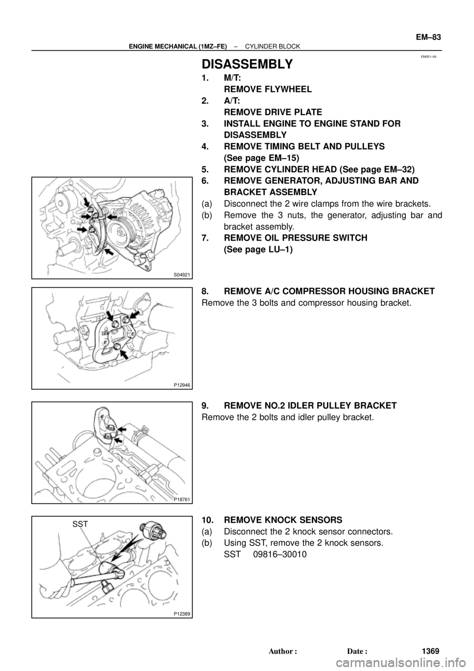
DISASSEMBLY
1. M/T:
REMOVE FLYWHEEL
2. A/T:
REMOVE DRIVE PLATE
3. INSTALL ENGINE TO ENGINE STAND FOR
DISASSEMBLY
4. REMOVE TIMING BELT AND PULLEYS
(See page EM±15)
5. REMOVE CYLINDER HEAD (See page EM±32)
6. REMOVE GENERATOR, ADJUSTING BAR AND
BRACKET ASSEMBLY
(a) Disconnect the 2 wire clamps from the wire brackets.
(b) Remove the 3 nuts, the generator, adjusting bar and
bracket assembly.
7. REMOVE OIL PRESSURE SWITCH
(See page LU±1)
8. REMOVE A/C COMPRESSOR HOUSING BRACKET
Remove the 3 bolts and compressor housing bracket.
9. REMOVE NO.2 IDLER PULLEY BRACKET
Remove the 2 bolts and idler pulley bracket.
10. REMOVE KNOCK SENSORS
(a) Disconnect the 2 knock sensor connectors.
(b) Using SST, remove the 2 knock sensors.
SST 09816±30010
Page 3615 of 4770
CYLINDER BLOCK
EM±109
1395 Author�: Date�: �
Using a non±residue solvent, clean both sealing
surfaces.
(")
P12909
Seal Width 3 ± 5 mm
Z14261
1
23
45 6
7
89
10
P12389
SST
± ENGINE MECHANICAL (1MZ±FE)CYLINDER BLOCK
EM±109
1395 Author�: Date�: �
Using a non±residue solvent, clean both sealing
surfaces.
(b) Apply seal packing to the water inlet housing as shown in
the illustration.
Seal packing: Part No. 08826±00100 or equivalent
�Install a nozzle that has been cut to a 3 ± 5 mm (0.12
± 0.20 in.) opening.
HINT:
Avoid applying an excessive amount to the surface.
�Parts must be assembled within 3 minutes of ap-
plication. Otherwise the material must be removed
and reapplied.
�Immediately remove nozzle from the tube and rein-
stall cap.
(c) Install the water inlet housing with the 8 bolts and 2 nuts.
Uniformly tighten the bolts and nuts, in several passes, in
the sequence shown.
Torque: 8 N´m (80 kgf´cm, 69 in.´lbf)
(d) Install the engine wire band.
(e) Install the engine wire clamp.
27. INSTALL KNOCK SENSORS
(a) Using SST, install the 2 knock sensors.
SST 09816±30010
Torque: 39 N´m (400 kgf´cm, 29 ft´lbf)
(b) Connect the 2 knock sensor connectors.
28. INSTALL NO.2 IDLER PULLEY BRACKET
Torque: 28 N´m (290 kgf´cm, 21 ft´lbf)
29. INSTALL A/C COMPRESSOR HOUSING BRACKET
Torque: 25 N´m (250 kgf´cm, 18 ft´lbf)
Page 3617 of 4770
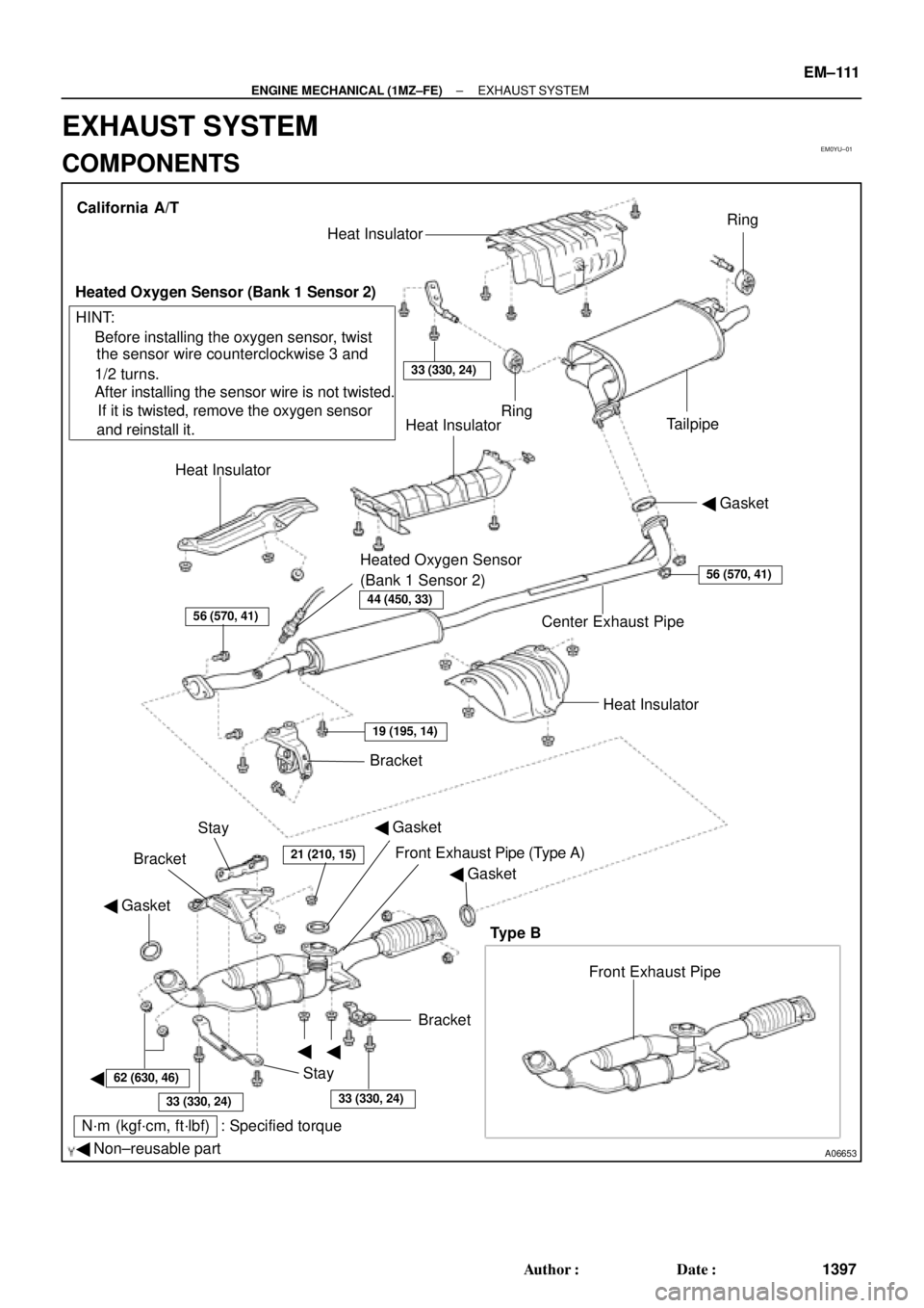
EM0YU±01
A06653
� Gasket
� Non±reusable part
N´m (kgf´cm, ft´lbf) : Specified torque� Gasket
�
�
�BracketFront Exhaust Pipe Bracket
StayHeat Insulator Center Exhaust Pipe� Gasket Heat InsulatorHeat Insulator
Heated Oxygen Sensor
(Bank 1 Sensor 2)TailpipeRing
Ring
33 (330, 24)
Heat Insulator
Heated Oxygen Sensor (Bank 1 Sensor 2)
� Before installing the oxygen sensor, twist
the sensor wire counterclockwise 3 and
1/2 turns.
If it is twisted, remove the oxygen sensor
and reinstall it. � After installing the sensor wire is not twisted. California A/T
Bracket
HINT:
56 (570, 41)
19 (195, 14)
21 (210, 15)
62 (630, 46)
33 (330, 24)33 (330, 24)
56 (570, 41)
Stay
Front Exhaust Pipe (Type A)
Type B
44 (450, 33)
� Gasket
± ENGINE MECHANICAL (1MZ±FE)EXHAUST SYSTEM
EM±111
1397 Author�: Date�:
EXHAUST SYSTEM
COMPONENTS
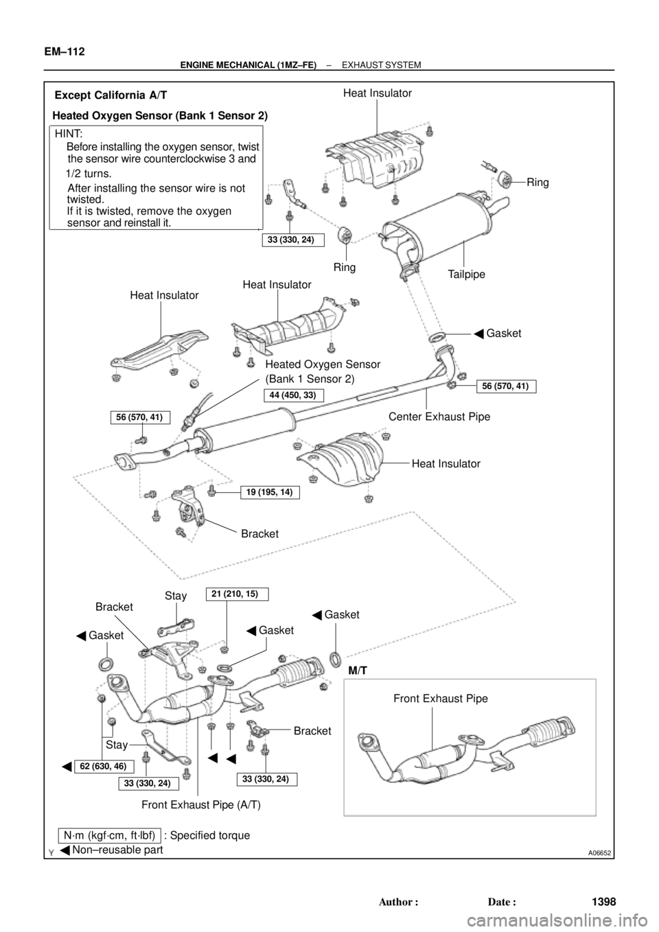
Page 3618 of 4770
A06652
� Gasket
� Non±reusable part
N´m (kgf´cm, ft´lbf) : Specified torque� Gasket
�
�� Gasket
�Bracket
Stay
Front Exhaust Pipe (A/T) BracketBracket
Stay
21 (210, 15)
Heat Insulator Center Exhaust Pipe� Gasket Heat InsulatorHeat Insulator
Heated Oxygen Sensor
(Bank 1 Sensor 2)TailpipeRing
Ring
33 (330, 24)
Heat Insulator
Heated Oxygen Sensor (Bank 1 Sensor 2)
� Before installing the oxygen sensor, twist
the sensor wire counterclockwise 3 and
1/2 turns.
If it is twisted, remove the oxygen
sensor and reinstall it. � After installing the sensor wire is notExcept California A/T
HINT:
56 (570, 41)
19 (195, 14)
62 (630, 46)
33 (330, 24)33 (330, 24)
56 (570, 41)
twisted.
Front Exhaust Pipe
M/T
44 (450, 33)
EM±112
± ENGINE MECHANICAL (1MZ±FE)EXHAUST SYSTEM
1398 Author�: Date�:
Page 3640 of 4770
BE0A4±04
I21685
E/G Room J/B No.2
� HEAD LH Fuse
(w/o Daytime Running Light)
� HEAD RH Fuse
(w/o Daytime Running Light)
� HEAD LH (UPR) Fuse
(w/ Daytime Running Light)
� HEAD RH (UPR) Fuse
(w/ Daytime Running Light)
� DOME Fuse
� ECU±B Fuse
� Headlight Control Relay
E/G Room R/B No.2
(w/ Daytime Running Light)
� HEAD LH (LWR) Fuse
� HEAD RH (LWR) Fuse
� DRL No.2 Fuse
� Daytime Running Light Relay No.2
� Daytime Running Light Relay No.3
� Daytime Running Light Relay No.4
Headlight
Instrument Panel J/B No.1
� GAUGE Fuse
� TAIL Fuse
� Taillight Control Relay
� Integration Relay
Daytime Running
Light Relay (Main)Ignition Switch
Combination Switch
� Light Control Switch
� Headlight Dimmer Switch
Door Courtesy Switch
Light Failure Sensor
Taillight
Automatic Light
Control Sensor
BE±22
± BODY ELECTRICALHEADLIGHT AND TAILLIGHT SYSTEM
2232 Author�: Date�:
2001 CAMRY (RM819U)
HEADLIGHT AND TAILLIGHT SYSTEM
LOCATION
Page 3644 of 4770

8. w/ Daytime running light system:
INSPECT DAYTIME RUNNING LIGHT")
Z08559
1
2
341 2
43
I08422
I08423
BE±26
± BODY ELECTRICALHEADLIGHT AND TAILLIGHT SYSTEM
2236 Author�: Date�:
2001 CAMRY (RM819U)
8. w/ Daytime running light system:
INSPECT DAYTIME RUNNING LIGHT NO.4 RELAY
CONTINUITY
ConditionTester connectionSpecified condition
Constant3 ± 4Continuity
Apply B+ between
terminals 3 and 4.1 ± 2Continuity
If continuity is not as specified, replace the relay.
9. INSPECT LIGHT AUTO TURN OFF SYSTEM
(See Integration relay circuit on page BE±14)
10. w/ Automatic Light Control System:
INSPECT AUTOMATIC LIGHT CONTROL
(a) Turn the ignition switch ON.
(b) Turn the light control switch to OFF.
(c) Parking brake lever released.
(d) Gradually cover the top of the sensor.
(e) Verify that the lights should turn ON the accessory lights
and the headlights.
11. w/ Automatic Light Control System:
INSPECT AUTOMATIC LIGHT CONTROL
(a) Gradually expose the sensor.
(b) Verify that the lights should turn OFF the headlights and
the accessory lights.
12. w/ Automatic Light Control System:
INSPECT LIGHT±OFF CONDITION
(a) Turn the ignition switch ON.
(b) Gradually cover the top of the sensor.
Lights auto ON:
13. w/ Automatic Light Control System:
INSPECT LIGHTS±ON CONDITION
(a) Open the driver's door while the ignition switch is OFF.
(b) Turn the light control switch to OFF leaving the door open
and cover the top of the sensor, and verify that the lights
go on when the ignition switch is turned ON.