Page 3329 of 4770
I08434
Instrument Panel J/B
Ignition Switch
ECU±IG
B 9 J12
J/C
B±YC15
B±R C
C
GND
IG1
2
B±R IG1
Battery24
AM1
Instrument Panel J/B
AM1 1K1
W
B±GF9
F41
W±B
FL MAINCruise Control ECU
1J9
B±R
1K
1B1
16
C15
W±B
W±BJ8A
J7AJ/C
1J8
1J7Instrument Panel J/B
A J11
J/C FL BLOCK
ALT
± DIAGNOSTICSCRUISE CONTROL SYSTEM
DI±909
1144 Author�: Date�:
ECU Power Source Circuit
CIRCUIT DESCRIPTION
The ECU power source supplies power to the actuator and sensors, etc, when terminal GND and the cruise
control ECU case are grounded.
WIRING DIAGRAM
DI08X±11
Page 3359 of 4770
EC03A±03
B06542
PCV Valve
VSV for EGR
Front TWC
(California)EGR Vacuum Modulator
EGR Valve
TWC (Except California)
Rear TWC (California)
VSV for EVAP
Vent Line
Charcoal Canister
Fuel Tank
EVAP Line
Air Drain Hose
Filler Pipe
Air Inlet LinePurge Line Cutoff Valve
Fill Check Valve
EVAP Service Port
Fuel Tank Cap
VSV for Vapor
Pressure Sensor Vapor Pressure Sensor
EC±2
± EMISSION CONTROL (5S±FE)PARTS LAYOUT AND SCHEMATIC DRAWING
1400 Author�: Date�:
PARTS LAYOUT AND SCHEMATIC DRAWING
LOCATION
Page 3360 of 4770
EC03B±03
B06549
VSV for EGR Front TWC
(California)EGR Vacuum Modulator
EGR
Valve
TWC (Except California)
Rear TWC (California)VSV
for EVAP
Vent Line
Charcoal CanisterFuel Tank EVAP Line
Air Drain HoseFiller Pipe
Air Inlet Line Purge LineEVAP Service Port
Fuel Tank Cap
Vapor
Pressure
SensorVSV for Vapor
Pressure Sensor
± EMISSION CONTROL (5S±FE)PARTS LAYOUT AND SCHEMATIC DRAWING
EC±3
1401 Author�: Date�:
DRAWING
Page 3362 of 4770
EC03D±05
B06534
Vapor Pressure Sensor
ConnectorVSV for Vapor Pressure Sensor
ConnectorEVAP Line Hose
Vent Line Hose
Air Inlet Line Hose
Purge Line Hose
Air Drain Hose
39.2 (400, 29)
N´m (kgf´cm, ft´lbf) : Specified torqueCharcoal Canister
Assembly
Charcoal Canister
Vapor Pressure Sensor
Mounting Bolt
± EMISSION CONTROL (5S±FE)EVAPORATIVE EMISSION (EVAP) CONTROL SYSTEM
EC±5
1403 Author�: Date�:
EVAPORATIVE EMISSION (EVAP) CONTROL SYSTEM
COMPONENTS
Page 3366 of 4770
EVAPORATIVE EMISSION (EVAP) CONTROL")
B01252
AirDisconnect
Air Inlet Line Hose
B01253
Pinch
Push
AA
Pinch
B01148
B01149
Air
Purge Port
Vent Port
Air Drain Port
Cap
EVAP
Port
± EMISSION CONTROL (5S±FE)EVAPORATIVE EMISSION (EVAP) CONTROL SYSTEM
EC±9
1407 Author�: Date�:
HINT:
In the condition that the fuel fuel is full, as the float value of the
fill check valve is closed and has no ventilation, it is necessary
to check the fuel amount (volume).
(d) Check if there is any struck in the vent line hose and EVAP
line hose.
If there is no stuck in hoses, replace the fuel cutoff valve and fill
check valve.
(e) Reconnect the purge line hose and EVAP line hose to the
charcoal canister.
7. CHECK AIR INLET LINE
(a) Disconnect the air inlet line hose from the charcoal canis-
ter.
(b) Check that there is ventilation in the air inlet line.
(c) Reconnect the air inlet line hose to the charcoal canister.
8. REMOVE CHARCOAL CANISTER ASSEMBLY
(a) Disconnect the VSV connector.
(b) Disconnect the vapor pressure sensor connector.
(c) Disconnect the purge line hose, EVAP line hose and air
inlet line hose from the charcoal canister.
(d) Disconnect the vent line hose from the charcoal canister.
(1) Push the connector deep inside.
(2) Pinch portion A.
(3) Pull out the connector.
(e) Remove the 2 charcoal canister mounting bolts.
(f) Remove the vapor pressure sensor mounting bolt.
(g) Remove the charcoal canister assembly.
9. INSPECT CHARCOAL CANISTER
(a) Visually check the charcoal canister for cracks or dam-
age.
(b) Inspect the charcoal canister operation.
(1) Plug the vent port with a cap.
(2) While holding the purge port closed, blow air (1.76
kPa, 18 gf/cm
2, 0.26 psi) into the EVAP port and
check that air flows from the air drain port.
Page 3367 of 4770
EVAPORATIVE EMISS")
B01150
Air
Purge Port
EVAP
Port Air Drain PortAir Inlet Port
B01151Vacuum
Purge PortAir Inlet Port
B01152Vacuum
Purge Port
EVAP
Port
Air Inlet Port
EC±10
± EMISSION CONTROL (5S±FE)EVAPORATIVE EMISSION (EVAP) CONTROL SYSTEM
1408 Author�: Date�:
(3) While holding the purge port and the air drain port
closed, blow air (1.76 kPa, 18 gf/cm
2, 0.26 psi) into
the EVAP port and check that air does not flow from
the air inlet port.
(4) Apply vacuum (3.43 kPa, 25.7 mmHg, 1.01 in.Hg)
to the purge port, check that the vacuum does not
decrease when the air inlet port is closed, and
check that the vacuum decreases when the air inlet
port is released.
(5) While holding the air inlet port closed, apply vacuum
(3.43 kPa, 25.7 mmHg, 1.01 in.Hg) to the EVAP port
and check that air flows into the purge port.
If operation is not as specified, replace the charcoal canister.
(6) Remove the cap from the vent port.
10. INSPECT VSV FOR EVAP (See page SF±45)
11. INSPECT VSV FOR VAPOR PRESSURE SENSOR
(See page SF±47)
12. INSPECT VAPOR PRESSURE SENSOR
(See page SF±55)
13. REINSTALL CHARCOAL CANISTER ASSEMBLY
Page 3373 of 4770
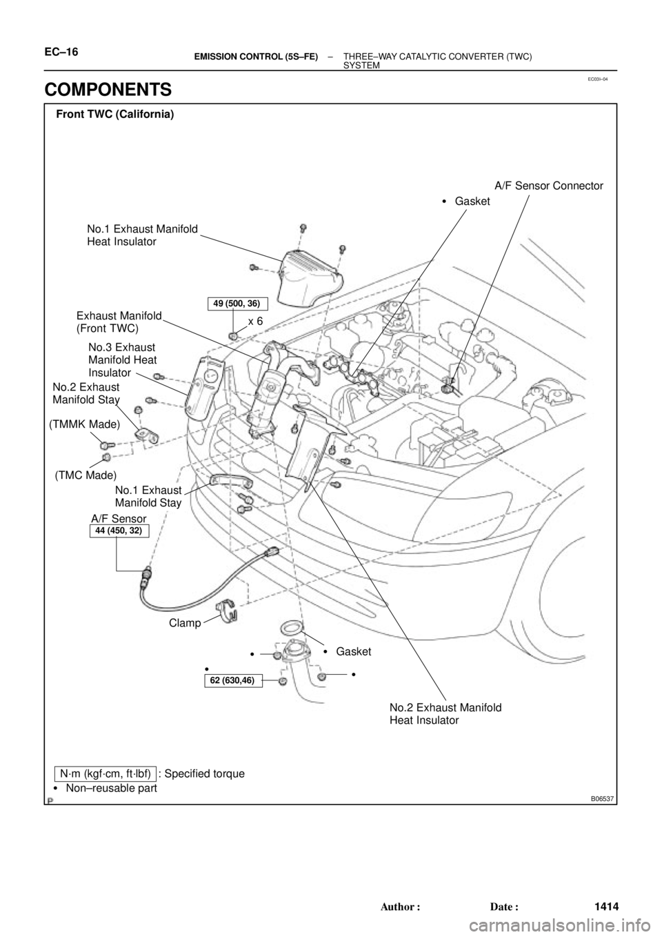
EC03I±04
B06537
Front TWC (California)
Exhaust Manifold
(Front TWC)
No.3 Exhaust
Manifold Heat
Insulator
No.2 Exhaust
Manifold Stay
A/F Sensor� GasketA/F Sensor Connector
� Gasket Clampx 6
�
�
N´m (kgf´cm, ft´lbf)
� Non±reusable part
49 (500, 36)
44 (450, 32)
62 (630,46)
: Specified torque
No.1 Exhaust
Manifold Stay
�
No.1 Exhaust Manifold
Heat Insulator
No.2 Exhaust Manifold
Heat Insulator
(TMC Made)
(TMMK Made)
EC±16± EMISSION CONTROL (5S±FE)THREE±WAY CATALYTIC CONVERTER (TWC)
SYSTEM
1414 Author�: Date�:
COMPONENTS
Page 3376 of 4770
EC01V±03
B06386
VSV for EGREGR Valve
Vent LineCharcoal Canister
Fuel Tank
EVAP Line
Air Drain Hose
Filler Pipe
Air Inlet Line
Purge Line
Cut Off Valve
Fill Check Valve
VSV for EVAP
VCVVacuum Surge Tank
EVAP Service Port
Vapor Pressure Sensor
Fuel Tank Cap
VSV for Vapor Pressure Sensor
Vacuum Surge Tank EC±2
± EMISSION CONTROL (1MZ±FE)PARTS LAYOUT AND SCHEMATIC DRAWING
1417 Author�: Date�:
PARTS LAYOUT AND SCHEMATIC DRAWING
LOCATION

EGR Vacuum Modulator
EGR Valve
TWC (Except California)
Rear TWC (California)
VSV for EVAP
Vent Line
Charcoal Canister
Fuel Tank
EVAP Line
A")
EGR Vacuum Modulator
EGR
Valve
TWC (Except California)
Rear TWC (California)VSV
for EVAP
Vent Line
Charcoal CanisterFuel Tank EVAP Line
Air Drain Hos")

N´m (kgf´cm, ft")