Page 4068 of 4770
SF0DR±03
S05534
(a)
(c)
(b)
B01283
SF±34
± SFI (5S±FE)THROTTLE BODY
1467 Author�: Date�:
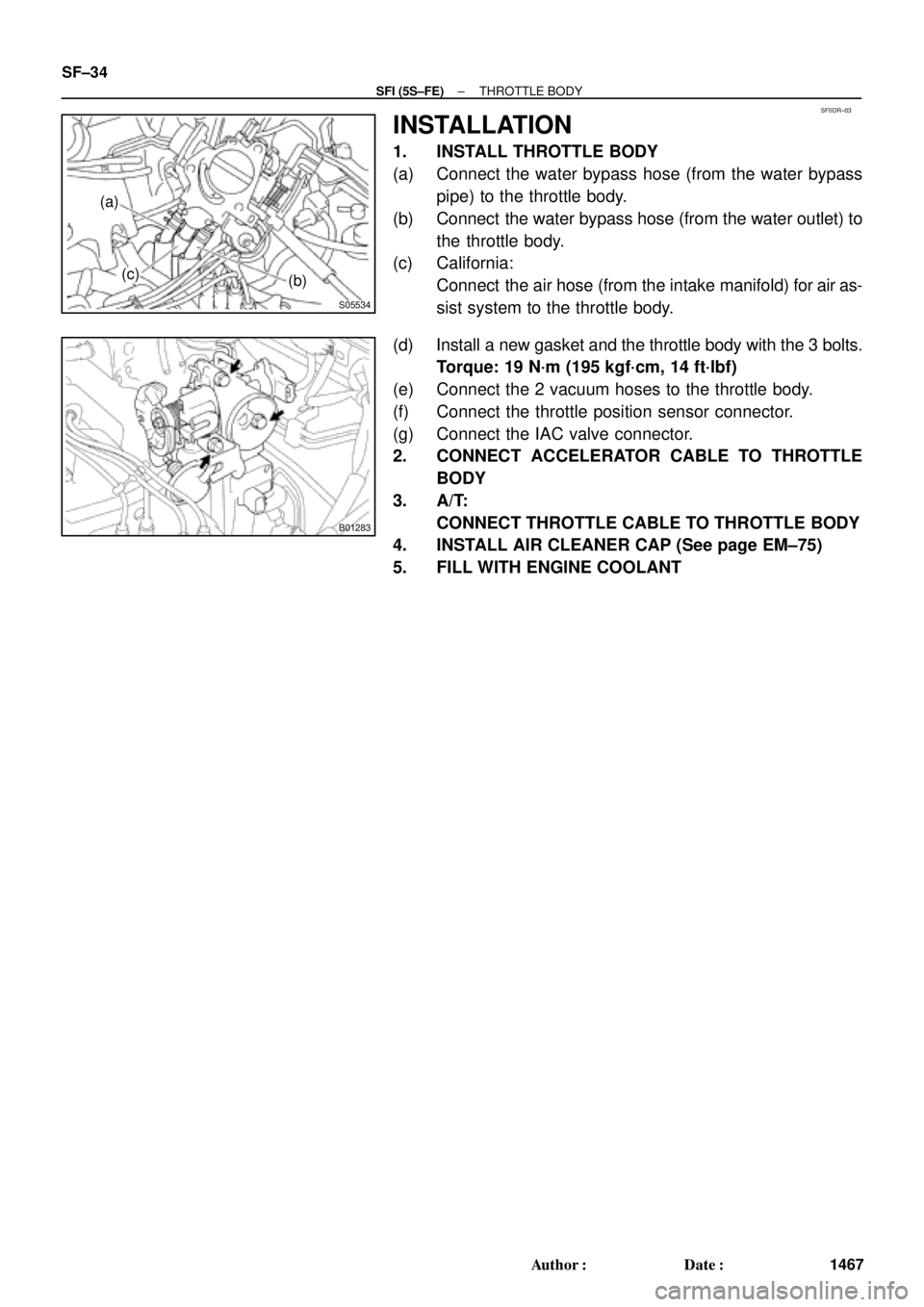
INSTALLATION
1. INSTALL THROTTLE BODY
(a) Connect the water bypass hose (from the water bypass
pipe) to the throttle body.
(b) Connect the water bypass hose (from the water outlet) to
the throttle body.
(c) California:
Connect the air hose (from the intake manifold) for air as-
sist system to the throttle body.
(d) Install a new gasket and the throttle body with the 3 bolts.
Torque: 19 N´m (195 kgf´cm, 14 ft´lbf)
(e) Connect the 2 vacuum hoses to the throttle body.
(f) Connect the throttle position sensor connector.
(g) Connect the IAC valve connector.
2. CONNECT ACCELERATOR CABLE TO THROTTLE
BODY
3. A/T:
CONNECT THROTTLE CABLE TO THROTTLE BODY
4. INSTALL AIR CLEANER CAP (See page EM±75)
5. FILL WITH ENGINE COOLANT
Page 4070 of 4770
SF0DT±03
B01285
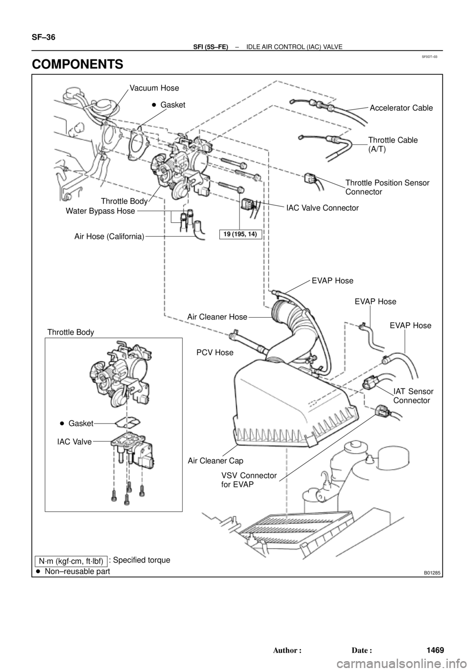
Vacuum Hose
� Gasket
Throttle Body
Water Bypass Hose
Air Hose (California)Accelerator Cable
Throttle Cable
(A/T)
Throttle Position Sensor
Connector
IAC Valve Connector
Air Cleaner Cap Air Cleaner Hose
IAC Valve
VSV Connector
for EVAPEVAP Hose
IAT Sensor
Connector PCV HoseEVAP Hose
EVAP Hose
19 (195, 14)
� Gasket
Throttle Body
N´m (kgf´cm, ft´lbf): Specified torque
� Non±reusable part
SF±36
± SFI (5S±FE)IDLE AIR CONTROL (IAC) VALVE
1469 Author�: Date�:
COMPONENTS
Page 4080 of 4770
SF0E3±03
B06550
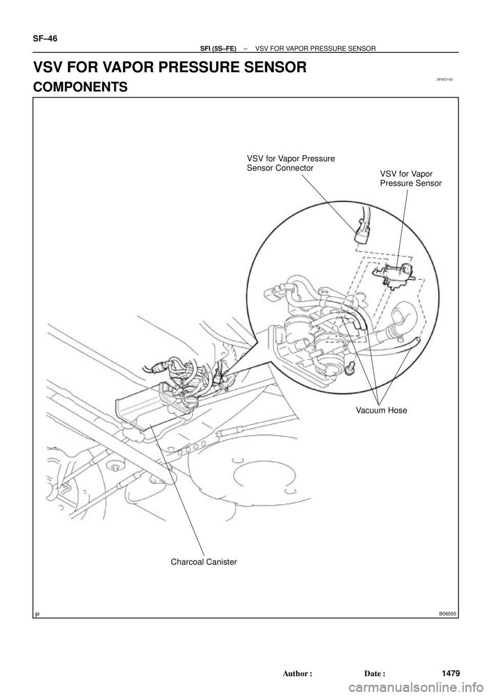
VSV for Vapor Pressure
Sensor Connector
VSV for Vapor
Pressure Sensor
Vacuum Hose
Charcoal Canister
SF±46
± SFI (5S±FE)VSV FOR VAPOR PRESSURE SENSOR
1479 Author�: Date�:
VSV FOR VAPOR PRESSURE SENSOR
COMPONENTS
Page 4081 of 4770
SF0E4±04
B01273
Ohmmeter
Continuity
B00798
Ohmmeter
No Continuity
B00799
Air
E
G
B00800
BatteryAir
F
E
± SFI (5S±FE)VSV FOR VAPOR PRESSURE SENSOR
SF±47
1480 Author�: Date�:
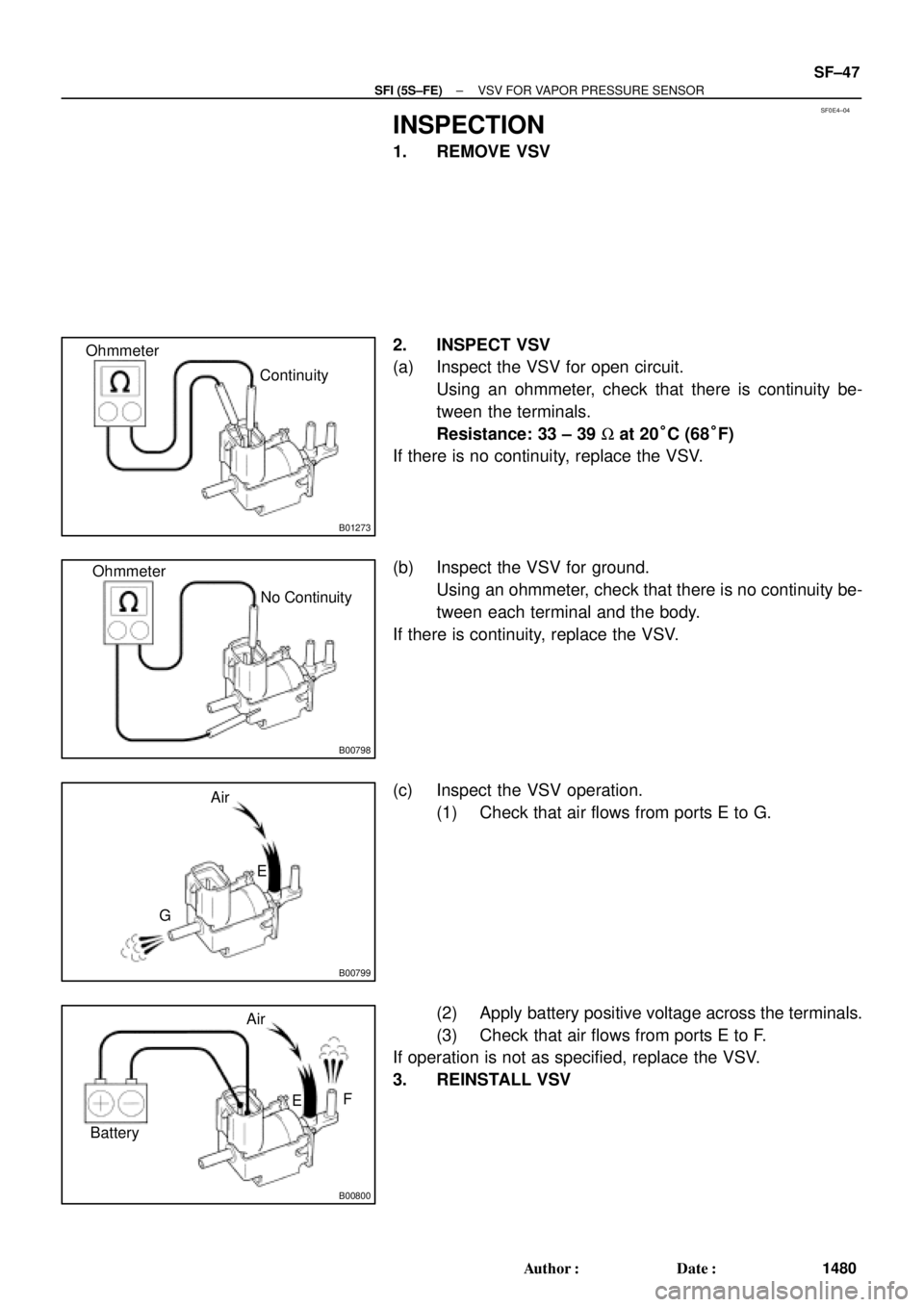
INSPECTION
1. REMOVE VSV
2. INSPECT VSV
(a) Inspect the VSV for open circuit.
Using an ohmmeter, check that there is continuity be-
tween the terminals.
Resistance: 33 ± 39 W at 20°C (68°F)
If there is no continuity, replace the VSV.
(b) Inspect the VSV for ground.
Using an ohmmeter, check that there is no continuity be-
tween each terminal and the body.
If there is continuity, replace the VSV.
(c) Inspect the VSV operation.
(1) Check that air flows from ports E to G.
(2) Apply battery positive voltage across the terminals.
(3) Check that air flows from ports E to F.
If operation is not as specified, replace the VSV.
3. REINSTALL VSV
Page 4082 of 4770
SF0E5±03
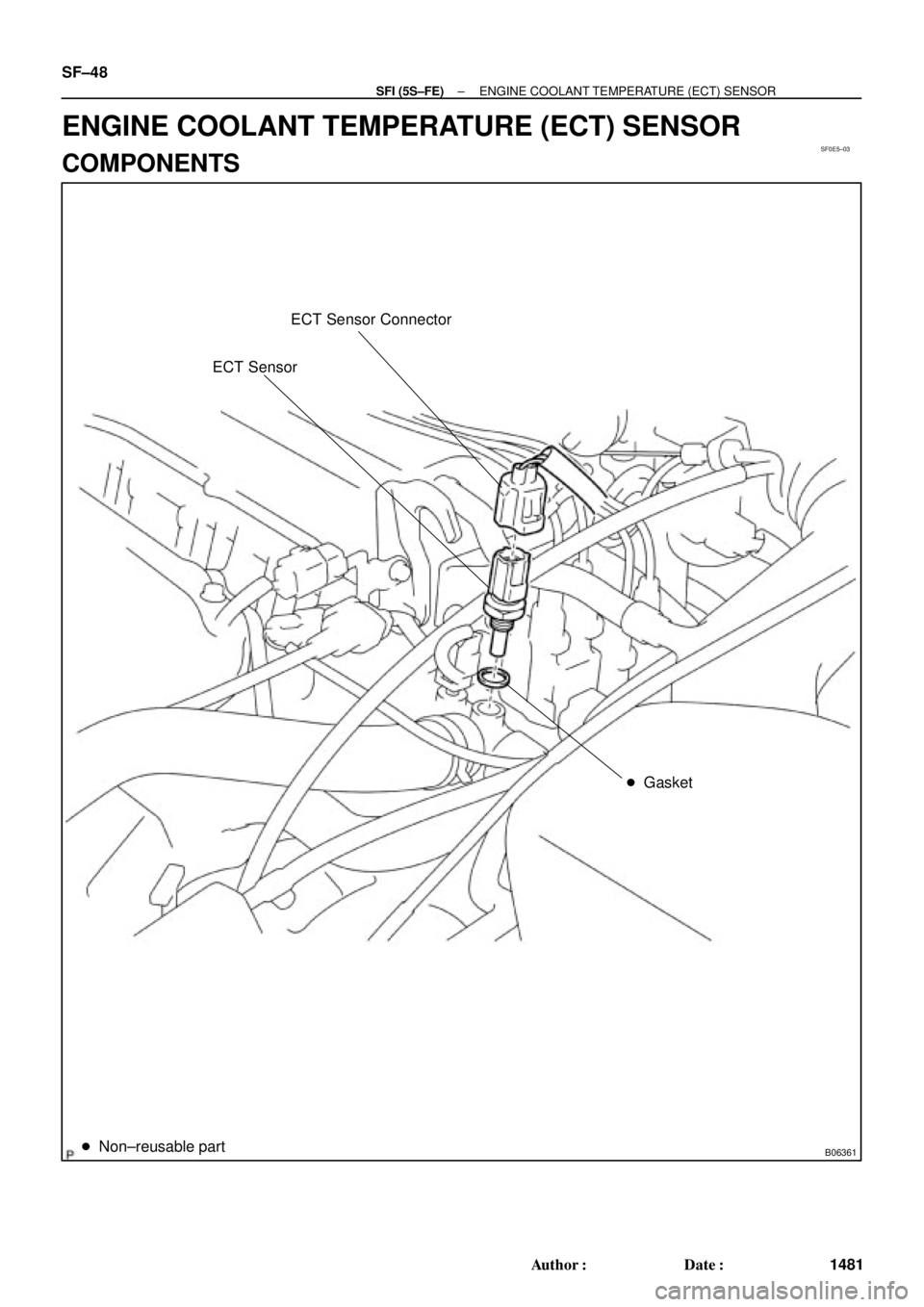
B06361
ECT Sensor Connector
ECT Sensor
� Gasket
� Non±reusable part
SF±48
± SFI (5S±FE)ENGINE COOLANT TEMPERATURE (ECT) SENSOR
1481 Author�: Date�:
ENGINE COOLANT TEMPERATURE (ECT) SENSOR
COMPONENTS
Page 4083 of 4770
SF0E6±03
S01196S01699Z17274
Ohmmeter
Resistance kW
Temperature °C (°F) Acceptable 30
20
10
5
3
2
1
0.5
0.3
0.2
0.1
40 ±20 0 20 60 80 100
(212) (176) (140) (104) (68) (32) (±4)
± SFI (5S±FE)ENGINE COOLANT TEMPERATURE (ECT) SENSOR
SF±49
1482 Author�: Date�:
INSPECTION
1. DRAIN ENGINE COOLANT
2. REMOVE ECT SENSOR
3. INSPECT ECT SENSOR
Using an ohmmeter, measure the resistance between the ter-
minals.
Resistance: Refer to the graph
If the resistance is not as specified, replace the ECT sensor.
4. REINSTALL ECT SENSOR
5. REFILL WITH ENGINE COOLANT
Page 4084 of 4770
SF0E7±03
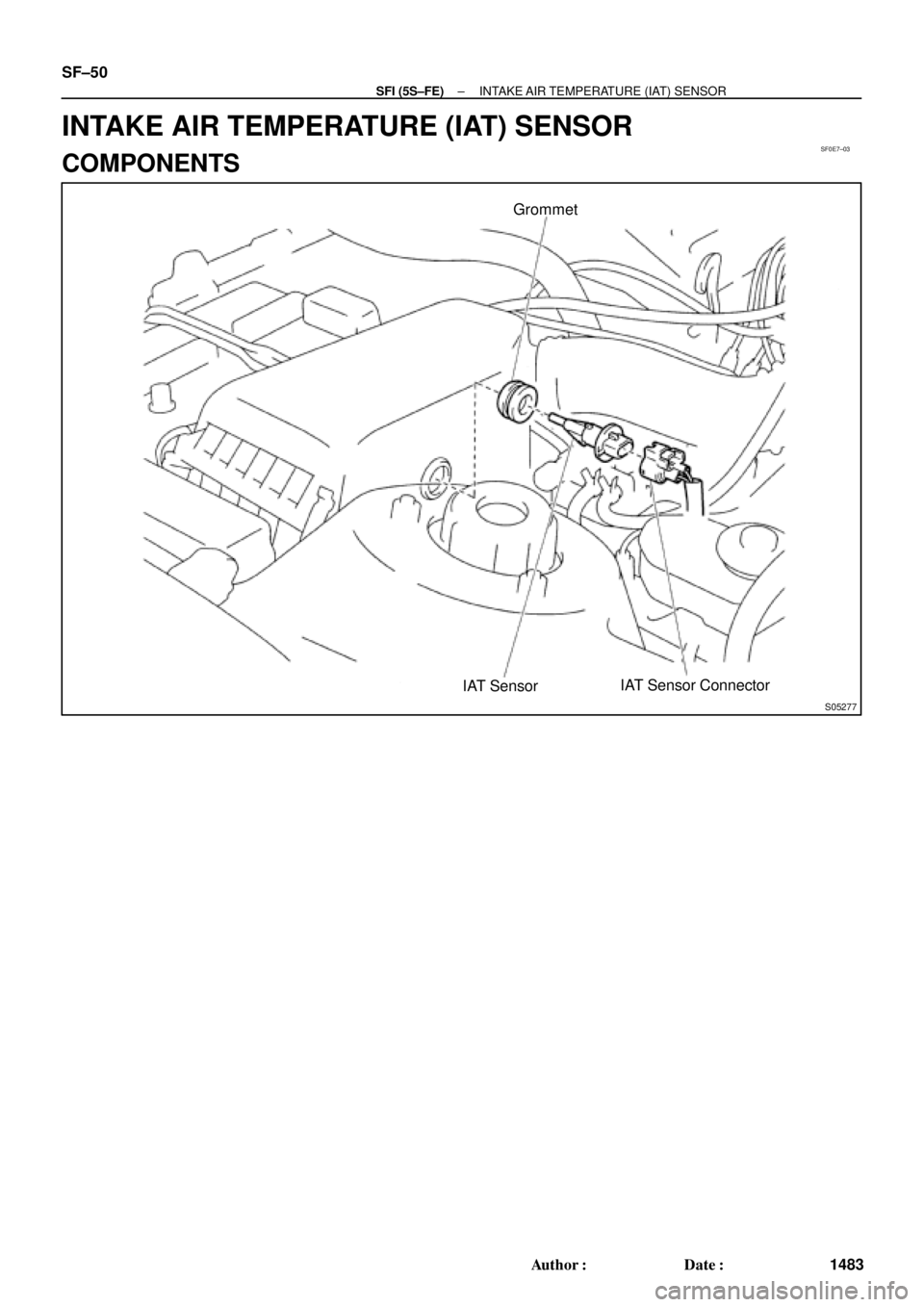
S05277
IAT SensorGrommet
IAT Sensor Connector SF±50
± SFI (5S±FE)INTAKE AIR TEMPERATURE (IAT) SENSOR
1483 Author�: Date�:
INTAKE AIR TEMPERATURE (IAT) SENSOR
COMPONENTS
Page 4085 of 4770
SF0E8±03
Z17273
Ohmmeter
Resistance kW
Temperature °C (°F) Acceptable 30
20
10
5
3
2
1
0.5
0.3
0.2
0.1
±20 20 40 60 800 100
(±4) (32)(68)(104)(140)(176)(212)
± SFI (5S±FE)INTAKE AIR TEMPERATURE (IAT) SENSOR
SF±51
1484 Author�: Date�:
INSPECTION
1. REMOVE IAT SENSOR
2. INSPECT IAT SENSOR
Using an ohmmeter, measure the resistance between the ter-
minals.
Resistance: Refer to the graph
If the resistance is not as specified, replace the sensor.
3. REINSTALL IAT SENSOR
 Acceptable 30
20
10
5
3
2
1
0.5
0.3
0.2
0.1
40 ±20 0 20 60 80 100
(212) (176) (140) (104) (68) (32) (±4)
± SFI (5S±FE)ENGI")
 Acceptable 30
20
10
5
3
2
1
0.5
0.3
0.2
0.1
±20 20 40 60 800 100
(±4) (32)(68)(104)(140)(176)(212)
± SFI (5S±FE)INTAKE AIR TEMPERATURE")