Page 4138 of 4770
SF07U±03
S04741
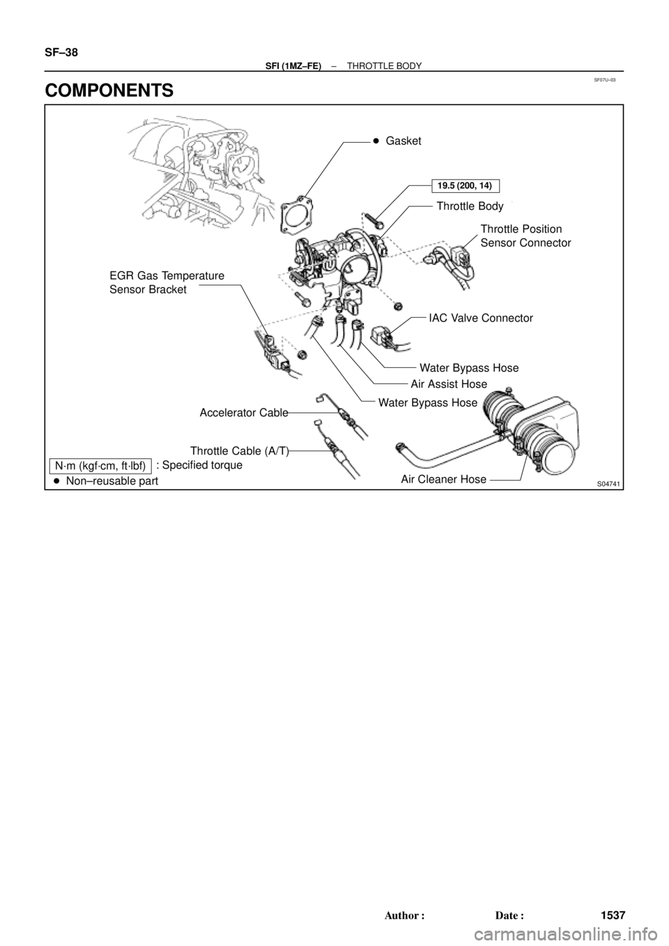
EGR Gas Temperature
Sensor Bracket� Gasket
Throttle Body
Throttle Position
Sensor Connector
IAC Valve Connector
Water Bypass Hose
Air Assist Hose
Water Bypass Hose
Air Cleaner Hose Accelerator Cable
Throttle Cable (A/T)
N´m (kgf´cm, ft´lbf)
� Non±reusable part: Specified torque
19.5 (200, 14)
SF±38
± SFI (1MZ±FE)THROTTLE BODY
1537 Author�: Date�:
COMPONENTS
Page 4139 of 4770
SF07V±03
S04506
S06123
(a)
(b)
(d) (e)
(c)
S04527
EGR Gas Temperature
Sensor Bracket
± SFI (1MZ±FE)THROTTLE BODY
SF±39
1538 Author�: Date�:
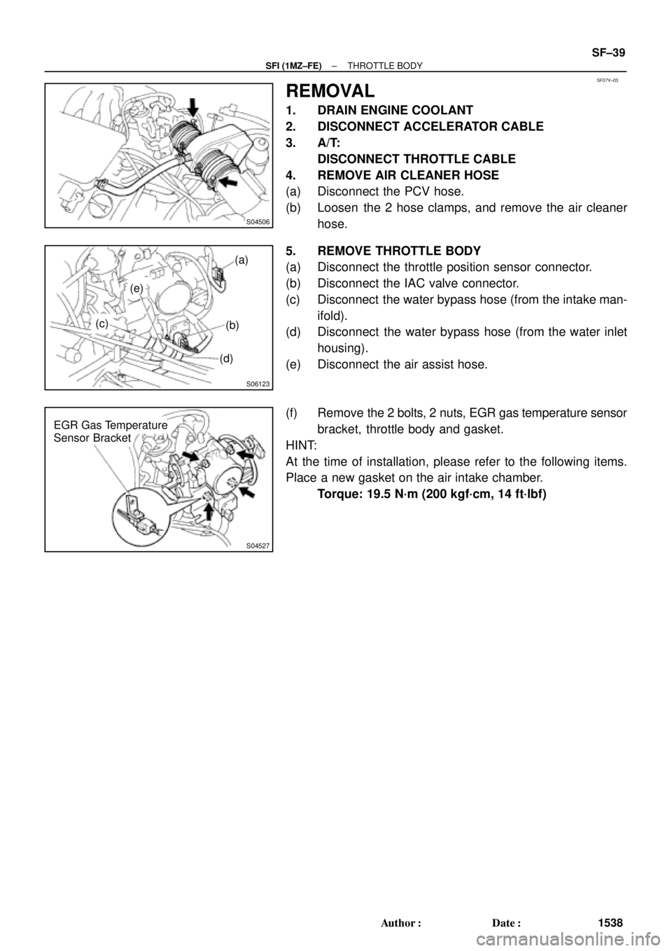
REMOVAL
1. DRAIN ENGINE COOLANT
2. DISCONNECT ACCELERATOR CABLE
3. A/T:
DISCONNECT THROTTLE CABLE
4. REMOVE AIR CLEANER HOSE
(a) Disconnect the PCV hose.
(b) Loosen the 2 hose clamps, and remove the air cleaner
hose.
5. REMOVE THROTTLE BODY
(a) Disconnect the throttle position sensor connector.
(b) Disconnect the IAC valve connector.
(c) Disconnect the water bypass hose (from the intake man-
ifold).
(d) Disconnect the water bypass hose (from the water inlet
housing).
(e) Disconnect the air assist hose.
(f) Remove the 2 bolts, 2 nuts, EGR gas temperature sensor
bracket, throttle body and gasket.
HINT:
At the time of installation, please refer to the following items.
Place a new gasket on the air intake chamber.
Torque: 19.5 N´m (200 kgf´cm, 14 ft´lbf)
Page 4140 of 4770
SF07W±03
S04582
S04595
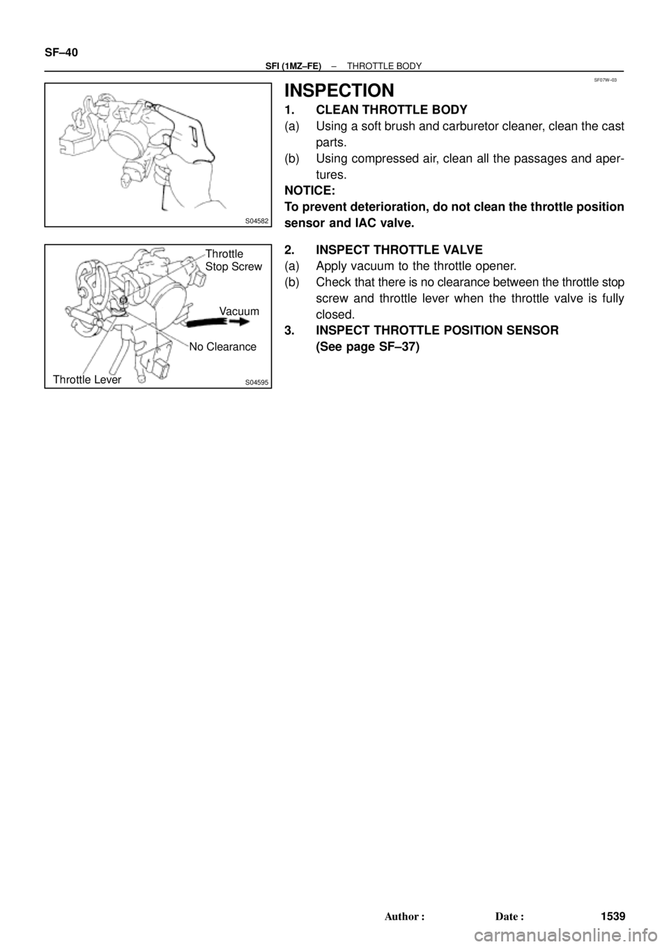
Throttle
Stop Screw
No Clearance
Throttle LeverVacuum SF±40
± SFI (1MZ±FE)THROTTLE BODY
1539 Author�: Date�:
INSPECTION
1. CLEAN THROTTLE BODY
(a) Using a soft brush and carburetor cleaner, clean the cast
parts.
(b) Using compressed air, clean all the passages and aper-
tures.
NOTICE:
To prevent deterioration, do not clean the throttle position
sensor and IAC valve.
2. INSPECT THROTTLE VALVE
(a) Apply vacuum to the throttle opener.
(b) Check that there is no clearance between the throttle stop
screw and throttle lever when the throttle valve is fully
closed.
3. INSPECT THROTTLE POSITION SENSOR
(See page SF±37)
Page 4144 of 4770
SF07Z±03
S04742
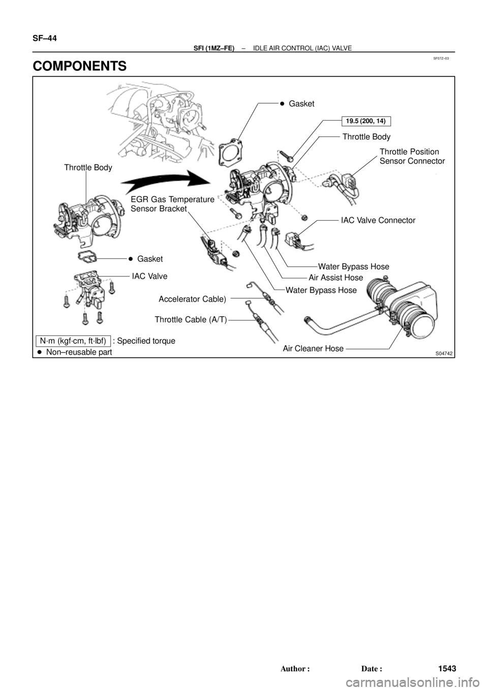
� Gasket
Throttle Body
Throttle Position
Sensor Connector
Water Bypass Hose
Air Cleaner HoseAir Assist Hose
Accelerator Cable)
Throttle Cable (A/T) EGR Gas Temperature
Sensor Bracket
N´m (kgf´cm, ft´lbf) : Specified torque
� Non±reusable partWater Bypass HoseIAC Valve Connector
19.5 (200, 14)
� Gasket Throttle Body
IAC Valve
SF±44
± SFI (1MZ±FE)IDLE AIR CONTROL (IAC) VALVE
1543 Author�: Date�:
COMPONENTS
Page 4161 of 4770
SF08G±03
B06550
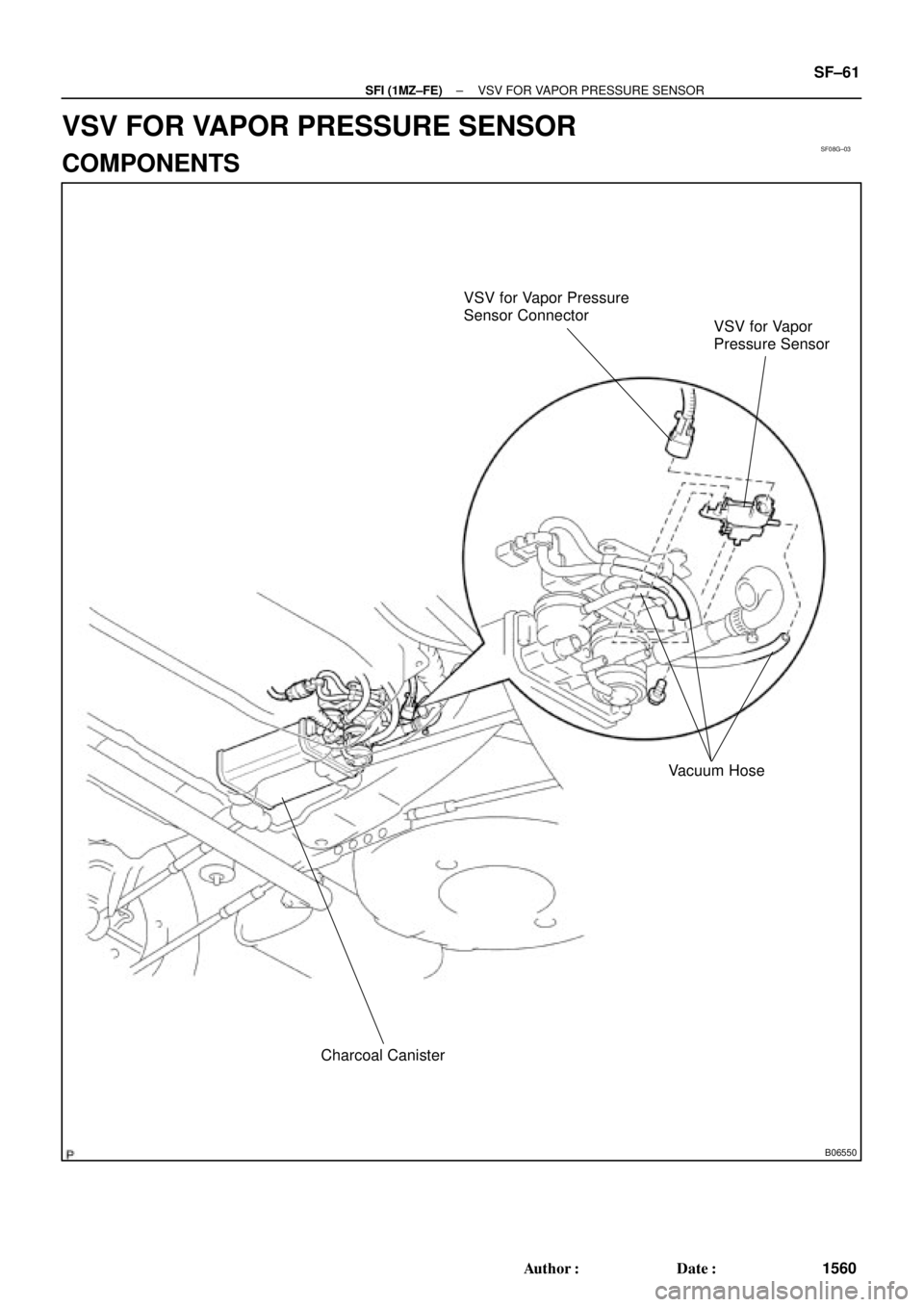
VSV for Vapor Pressure
Sensor Connector
VSV for Vapor
Pressure Sensor
Vacuum Hose
Charcoal Canister
± SFI (1MZ±FE)VSV FOR VAPOR PRESSURE SENSOR
SF±61
1560 Author�: Date�:
VSV FOR VAPOR PRESSURE SENSOR
COMPONENTS
Page 4162 of 4770
SF08H±03
B01273
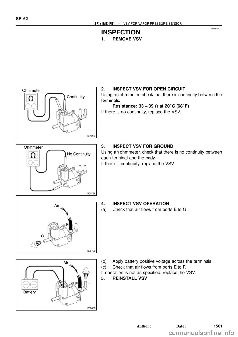
Ohmmeter
Continuity
B00798
Ohmmeter
No Continuity
B00799
Air
E
G
B00800
BatteryAir
F
E SF±62
± SFI (1MZ±FE)VSV FOR VAPOR PRESSURE SENSOR
1561 Author�: Date�:
INSPECTION
1. REMOVE VSV
2. INSPECT VSV FOR OPEN CIRCUIT
Using an ohmmeter, check that there is continuity between the
terminals.
Resistance: 33 ± 39 W at 20°C (68°F)
If there is no continuity, replace the VSV.
3. INSPECT VSV FOR GROUND
Using an ohmmeter, check that there is no continuity between
each terminal and the body.
If there is continuity, replace the VSV.
4. INSPECT VSV OPERATION
(a) Check that air flows from ports E to G.
(b) Apply battery positive voltage across the terminals.
(c) Check that air flows from ports E to F.
If operation is not as specified, replace the VSV.
5. REINSTALL VSV
Page 4163 of 4770
SF08I±03
S04759
ECT Switch19 mm
Deep Socket
Wrench
Gasket
S01196S01699Z17274
Ohmmeter
Resistance kW
Temperature °C (°F) Acceptable 30
20
10
5
3
2
1
0.5
0.3
0.2
0.1
40 ±20 0 20 60 80 100
(212) (176) (140) (104) (68) (32) (±4)
± SFI (1MZ±FE)ENGINE COOLANT TEMPERATURE (ECT) SENSOR
SF±63
1562 Author�: Date�:
ENGINE COOLANT
TEMPERATURE (ECT) SENSOR
INSPECTION
1. DRAIN ENGINE COOLANT
2. REMOVE ECT SENSOR
(a) Disconnect the ECT sensor connector.
(b) Using a 19 mm deep socket wrench, remove the ECT
sensor and gasket.
3. INSPECT ECT SENSOR
Using an ohmmeter, measure the resistance between the ter-
minals.
Resistance: Refer to the graph
If the resistance is not as specified, replace the ECT sensor.
4. REINSTALL ECT SENSOR
(a) Install a new gasket to the ECT sensor.
(b) Using a 19 mm deep socket, install the ECT sensor.
Torque: 20 N´m (200 kgf´cm, 14 ft´lbf)
(c) Connect the ECT sensor connector.
5. REFILL WITH ENGINE COOLANT
Page 4164 of 4770
SF0Z9±01
B06554
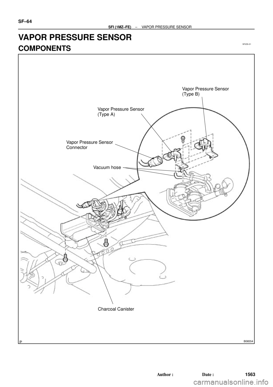
Charcoal Canister Vapor Pressure Sensor
(Type A)Vapor Pressure Sensor
(Type B)
Vapor Pressure Sensor
Connector
Vacuum hose
SF±64
± SFI (1MZ±FE)VAPOR PRESSURE SENSOR
1563 Author�: Date�:
VAPOR PRESSURE SENSOR
COMPONENTS
 Acceptable 30
20
10
5
3
2
1
0.5
0.3
0.2
0.1
40 ±20 0 20 60 80 100
(212) (176")