Page 4086 of 4770
SF0E9±03
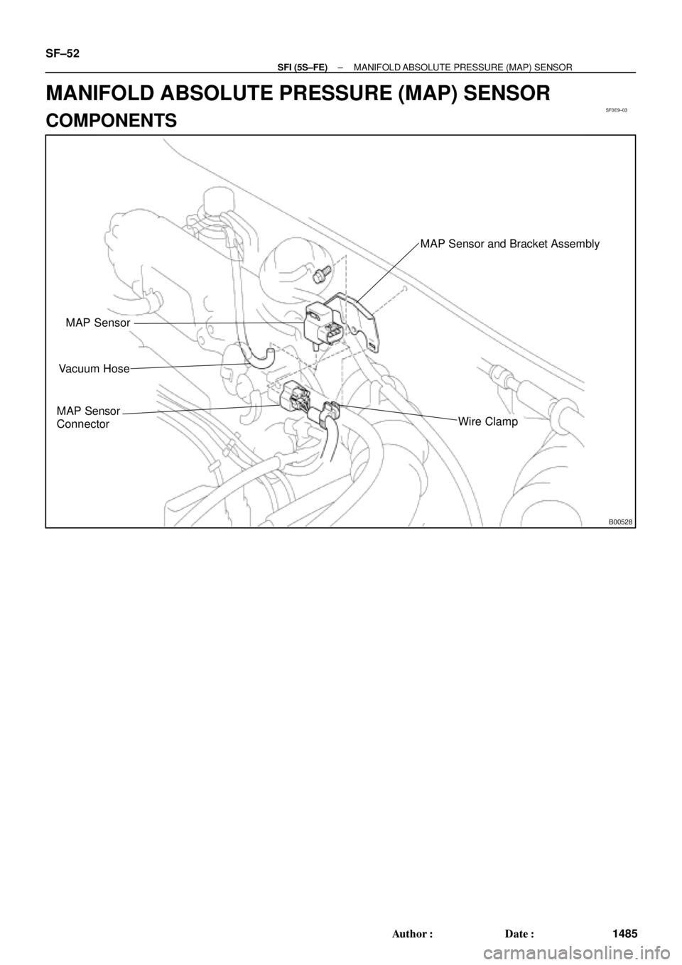
B00528
MAP Sensor
Vacuum Hose
MAP Sensor
Connector
MAP Sensor and Bracket Assembly
Wire Clamp
SF±52
± SFI (5S±FE)MANIFOLD ABSOLUTE PRESSURE (MAP) SENSOR
1485 Author�: Date�:
MANIFOLD ABSOLUTE PRESSURE (MAP) SENSOR
COMPONENTS
Page 4087 of 4770
E2 (±) Voltmeter
Voltage Drop:
Applied
Vacuum
kPa
mmHg
in.Hg
Vo l t a ge
d")
SF0EA±03
S05545
DisconnectOhmmeter
E2
VC
A03009B01912
w/o Immobilizer
w/ ImmobiliserDisconnect
Vacuum
PIM
E2 ECM
ECM PIM (+)E2 (±) Voltmeter
Voltage Drop:
Applied
Vacuum
kPa
mmHg
in.Hg
Vo l t a ge
drop V13.3
100
3.94
0.3 ± 0.5
26.7 40.0 53.5 66.7
200
7.87
300
11.81400
15.75500
19.69
0.7 ± 0.9 1.1 ± 1.3 1.5 ± 1.7 1.9 ± 2.1
± SFI (5S±FE)MANIFOLD ABSOLUTE PRESSURE (MAP) SENSOR
SF±53
1486 Author�: Date�:
INSPECTION
1. INSPECT POWER SOURCE VOLTAGE OF MAP SEN-
SOR
(a) Disconnect the MAP sensor connector.
(b) Turn the ignition switch ON.
(c) Using a voltmeter, measure the voltage between connec-
tor terminals VC and E2 of the wiring harness side.
Voltage: 4.5 ± 5.5 V
(d) Turn the ignition switch OFF.
(e) Reconnect the MAP sensor connector.
2. INSPECT POWER OUTPUT OF MAP SENSOR
(a) Turn the ignition switch ON.
(b) Disconnect the vacuum hose from the MAP sensor.
(c) Connect a voltmeter to terminals PIM and E2 of the ECM,
and measure the output voltage under ambient atmo-
spheric pressure.
(d) Apply vacuum to the MAP sensor in 13.3 kPa (100 mmHg,
3.94 in.Hg) segments to 66.7 kPa (500 mmHg, 19.69
in.Hg).
(e) Measure the voltage drop from step (c) above for each
segment.
(f) Turn the ignition switch OFF.
(g) Reconnect the vacuum hose to the MAP sensor.
Page 4088 of 4770
SF0EF±04
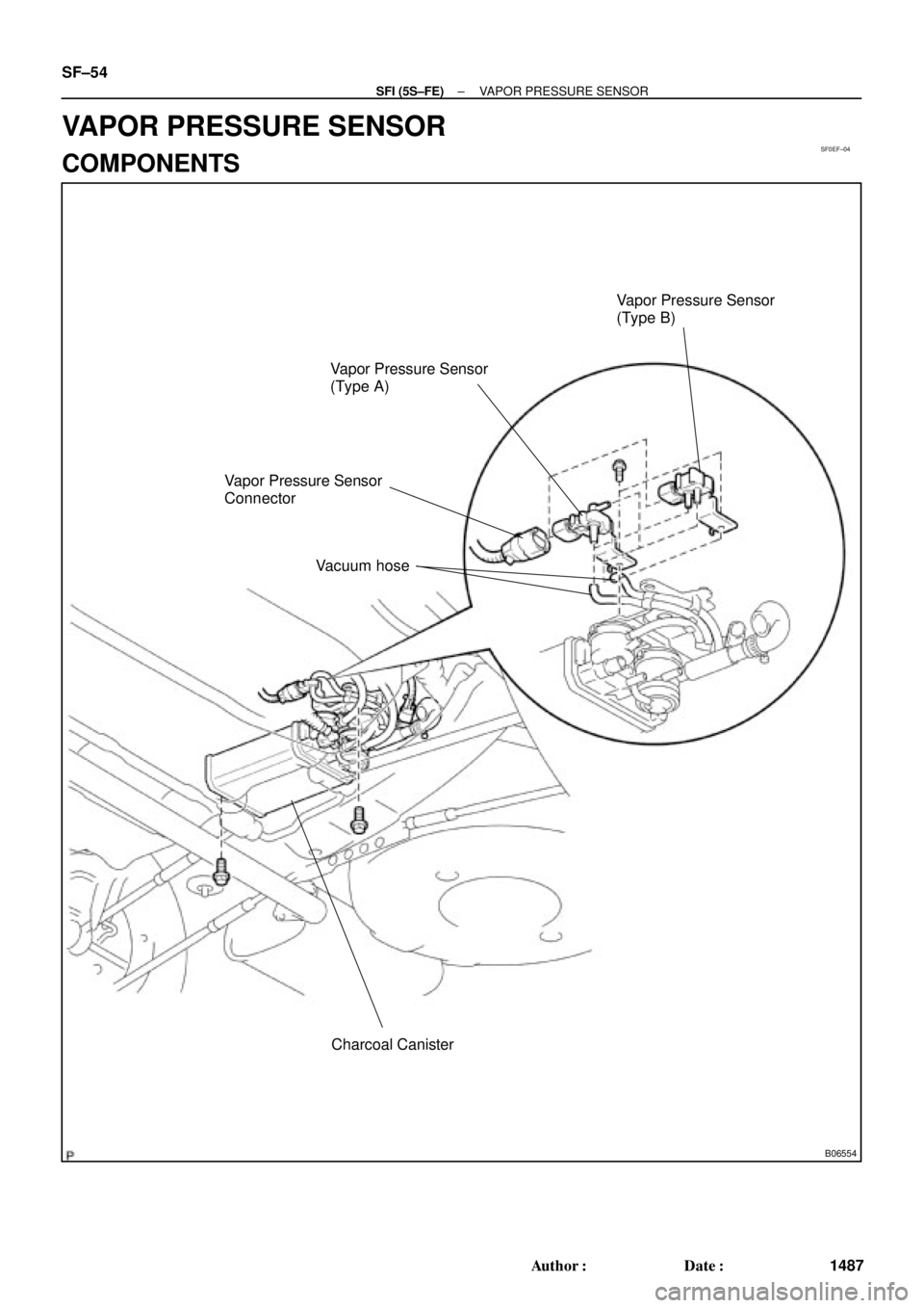
B06554
Charcoal Canister Vapor Pressure Sensor
(Type A)Vapor Pressure Sensor
(Type B)
Vapor Pressure Sensor
Connector
Vacuum hose
SF±54
± SFI (5S±FE)VAPOR PRESSURE SENSOR
1487 Author�: Date�:
VAPOR PRESSURE SENSOR
COMPONENTS
Page 4089 of 4770
 E2 (±) w/ Immobiliser
ECM
w/o Immobiliser
Pressur")
SF0EG±03
B06551
Disconnect
VC
E2Voltmeter
A03018S05603B06553B06552
B06570
Vacuum
Disconnect
ECME2
Disconnect
Pressure
Vacuum
PTNK
Voltmeter
PTNK (+) E2 (±) w/ Immobiliser
ECM
w/o Immobiliser
Pressure
Type A
Type B
P
± SFI (5S±FE)VAPOR PRESSURE SENSOR
SF±55
1488 Author�: Date�:
INSPECTION
1. INSPECT POWER SOURCE VOLTAGE OF VAPOR
PRESSURE SENSOR
(a) Disconnect the vapor pressure sensor connector.
(b) Turn the ignition switch ON.
(c) Using a voltmeter, measure the voltage between connec-
tor terminals VC and E2 of the wiring harness side.
Voltage: 4.5 ± 5.5 V
(d) Turn the ignition switch OFF.
(e) Reconnect the vapor pressure sensor connector.
2. INSPECT POWER OUTPUT OF VAPOR PRESSURE
SENSOR
(a) Turn the ignition switch ON.
(b) Disconnect the vacuum hose from the vapor pressure
sensor.
(c) Connect a voltmeter to terminals PTNK and E2 of the
ECM, and measure the output voltage under the following
conditions:
(1) Apply vacuum (2.0 kPa (15 mmHg, 0.59 in.Hg)) to
the vapor pressure sensor.
Voltage: 1.3 ± 2.1 V
(2) Release the vacuum from the vapor pressure sen-
sor.
Voltage: 3.0 ± 3.6 V
(3) Apply pressure (1.5 kPa (15 gf/cm
2, 0.22 psi)) to the
vapor pressure sensor.
Voltage: 4.2 ± 4.8 V
(d) Turn the ignition switch OFF.
(e) Reconnect the vacuum hose to the vapor pressure sen-
sor.
Page 4090 of 4770
SF0ED±03
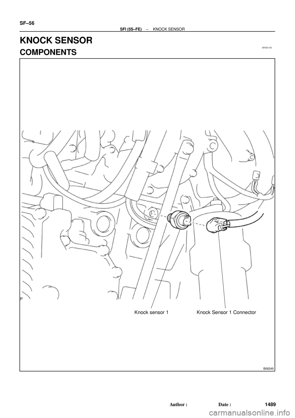
B06349
Knock sensor 1 Knock Sensor 1 Connector
SF±56
± SFI (5S±FE)KNOCK SENSOR
1489 Author�: Date�:
KNOCK SENSOR
COMPONENTS
Page 4091 of 4770
SF0EE±03
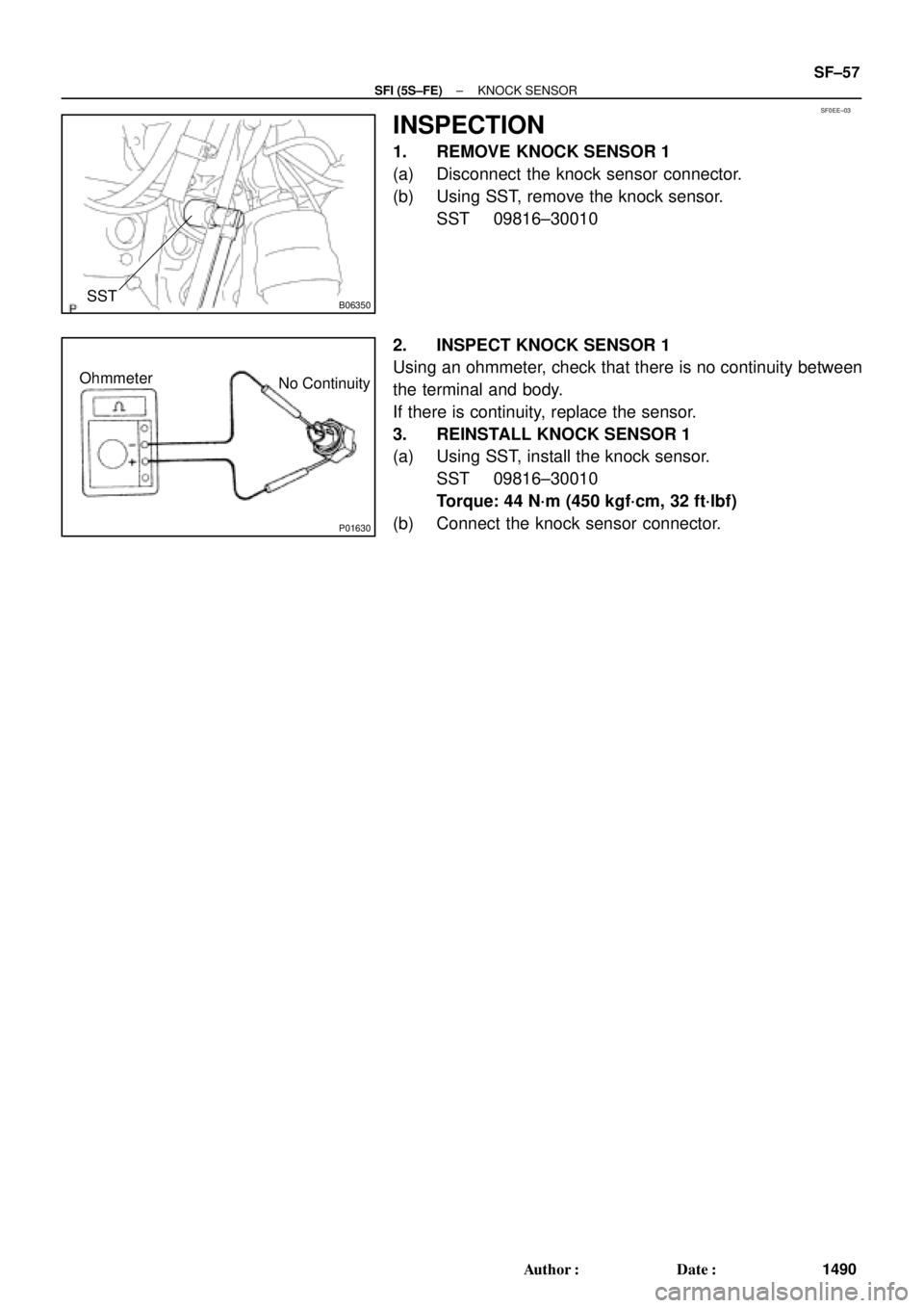
B06350SST
P01630
Ohmmeter
No Continuity
± SFI (5S±FE)KNOCK SENSOR
SF±57
1490 Author�: Date�:
INSPECTION
1. REMOVE KNOCK SENSOR 1
(a) Disconnect the knock sensor connector.
(b) Using SST, remove the knock sensor.
SST 09816±30010
2. INSPECT KNOCK SENSOR 1
Using an ohmmeter, check that there is no continuity between
the terminal and body.
If there is continuity, replace the sensor.
3. REINSTALL KNOCK SENSOR 1
(a) Using SST, install the knock sensor.
SST 09816±30010
Torque: 44 N´m (450 kgf´cm, 32 ft´lbf)
(b) Connect the knock sensor connector.
Page 4092 of 4770
SF0EB±03
B06358
No.3 Exhaust Manifold Heat Insulator
A/F Sensor Connector
Clamp
A/F Sensor
N´m (kgf´cm, ft´lbf): Specified torque
44 (450, 32)
SF±58
± SFI (5S±FE)AIR±FUEL RATIO (A/F) SENSOR (California)
1491 Author�: Date�:
AIR±FUEL RATIO (A/F) SENSOR (California)
COMPONENTS
Page 4093 of 4770
SF0EC±04
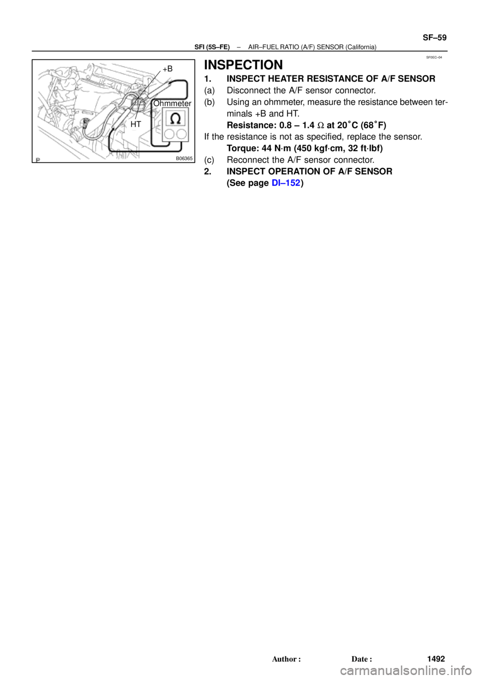
B06365
Ohmmeter
+B
HT
± SFI (5S±FE)AIR±FUEL RATIO (A/F) SENSOR (California)
SF±59
1492 Author�: Date�:
INSPECTION
1. INSPECT HEATER RESISTANCE OF A/F SENSOR
(a) Disconnect the A/F sensor connector.
(b) Using an ohmmeter, measure the resistance between ter-
minals +B and HT.
Resistance: 0.8 ± 1.4 W at 20°C (68°F)
If the resistance is not as specified, replace the sensor.
Torque: 44 N´m (450 kgf´cm, 32 ft´lbf)
(c) Reconnect the A/F sensor connector.
2. INSPECT OPERATION OF A/F SENSOR
(See page DI±152)
: Specified torque
44 (450, 32)
SF±58
± SFI (5S±FE)AIR±FUEL RATIO (A/F) SENSOR (C")