2000 NISSAN PATROL turn signal
[x] Cancel search: turn signalPage 30 of 1033
Self-diagnosis
After performing this procedure, place check marks for results on
the ªDIAGNOSTIC WORKSHEETº, AT-1038. Reference pages
are provided following the items.
SELF-DIAGNOSTIC PROCEDURE (With
CONSULT-II)
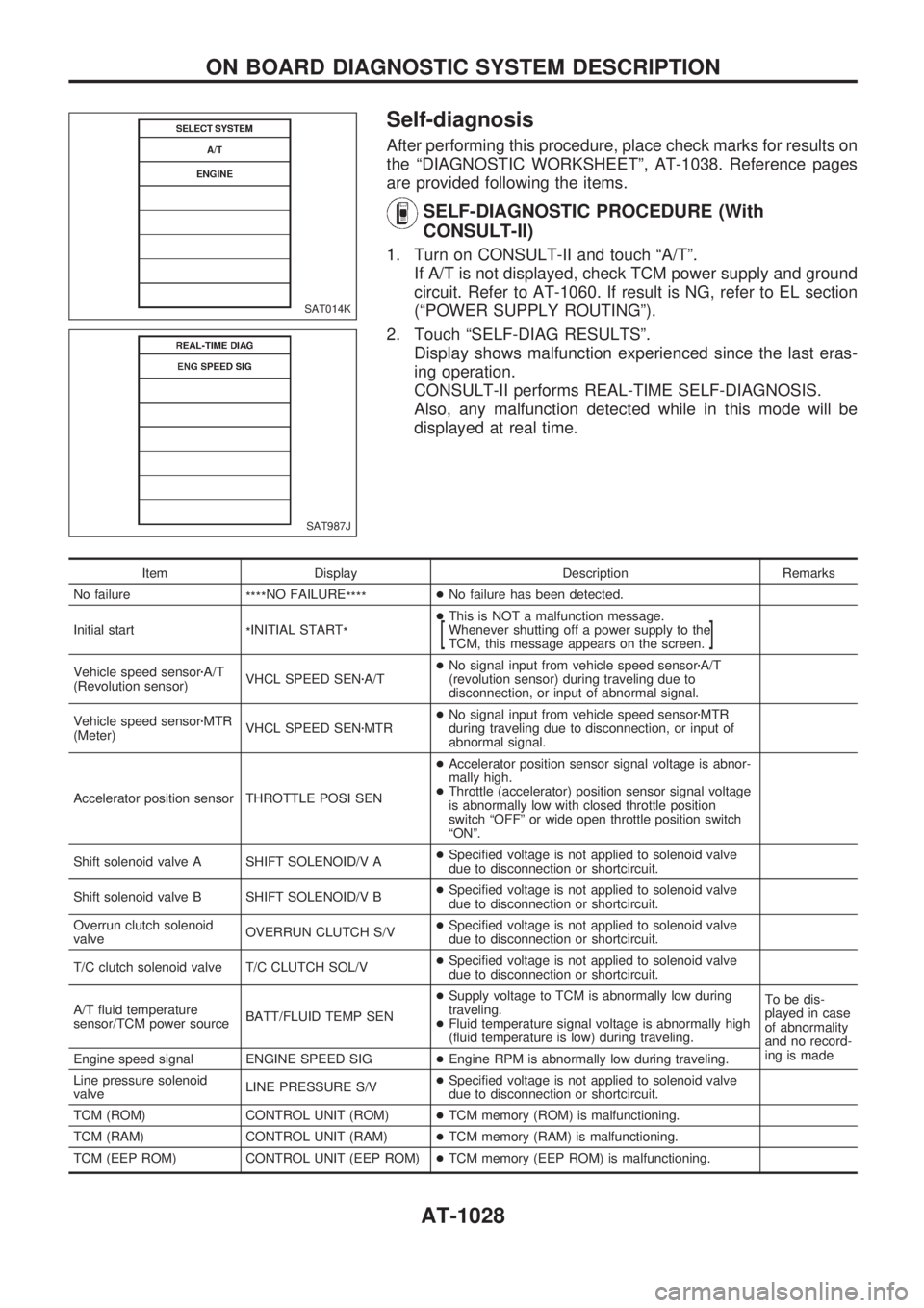
1. Turn on CONSULT-II and touch ªA/Tº.
If A/T is not displayed, check TCM power supply and ground
circuit. Refer to AT-1060. If result is NG, refer to EL section
(ªPOWER SUPPLY ROUTINGº).
2. Touch ªSELF-DIAG RESULTSº.
Display shows malfunction experienced since the last eras-
ing operation.
CONSULT-II performs REAL-TIME SELF-DIAGNOSIS.
Also, any malfunction detected while in this mode will be
displayed at real time.
Item Display Description Remarks
No failure
****NO FAILURE
****+No failure has been detected.
Initial start
*INITIAL START
*+This is NOT a malfunction message.
Whenever shutting off a power supply to the
TCM, this message appears on the screen.
[]
Vehicle speed sensorzA/T
(Revolution sensor)VHCL SPEED SENzA/T+No signal input from vehicle speed sensorzA/T
(revolution sensor) during traveling due to
disconnection, or input of abnormal signal.
Vehicle speed sensorzMTR
(Meter)VHCL SPEED SENzMTR+No signal input from vehicle speed sensorzMTR
during traveling due to disconnection, or input of
abnormal signal.
Accelerator position sensor THROTTLE POSI SEN+Accelerator position sensor signal voltage is abnor-
mally high.
+Throttle (accelerator) position sensor signal voltage
is abnormally low with closed throttle position
switch ªOFFº or wide open throttle position switch
ªONº.
Shift solenoid valve A SHIFT SOLENOID/V A+Specified voltage is not applied to solenoid valve
due to disconnection or shortcircuit.
Shift solenoid valve B SHIFT SOLENOID/V B+Specified voltage is not applied to solenoid valve
due to disconnection or shortcircuit.
Overrun clutch solenoid
valveOVERRUN CLUTCH S/V+Specified voltage is not applied to solenoid valve
due to disconnection or shortcircuit.
T/C clutch solenoid valve T/C CLUTCH SOL/V+Specified voltage is not applied to solenoid valve
due to disconnection or shortcircuit.
A/T fluid temperature
sensor/TCM power sourceBATT/FLUID TEMP SEN+Supply voltage to TCM is abnormally low during
traveling.
+Fluid temperature signal voltage is abnormally high
(fluid temperature is low) during traveling.To be dis-
played in case
of abnormality
and no record-
ing is made
Engine speed signal ENGINE SPEED SIG+Engine RPM is abnormally low during traveling.
Line pressure solenoid
valveLINE PRESSURE S/V+Specified voltage is not applied to solenoid valve
due to disconnection or shortcircuit.
TCM (ROM) CONTROL UNIT (ROM)+TCM memory (ROM) is malfunctioning.
TCM (RAM) CONTROL UNIT (RAM)+TCM memory (RAM) is malfunctioning.
TCM (EEP ROM) CONTROL UNIT (EEP ROM)+TCM memory (EEP ROM) is malfunctioning.
SAT014K
SAT987J
ON BOARD DIAGNOSTIC SYSTEM DESCRIPTION
AT-1028
Page 40 of 1033
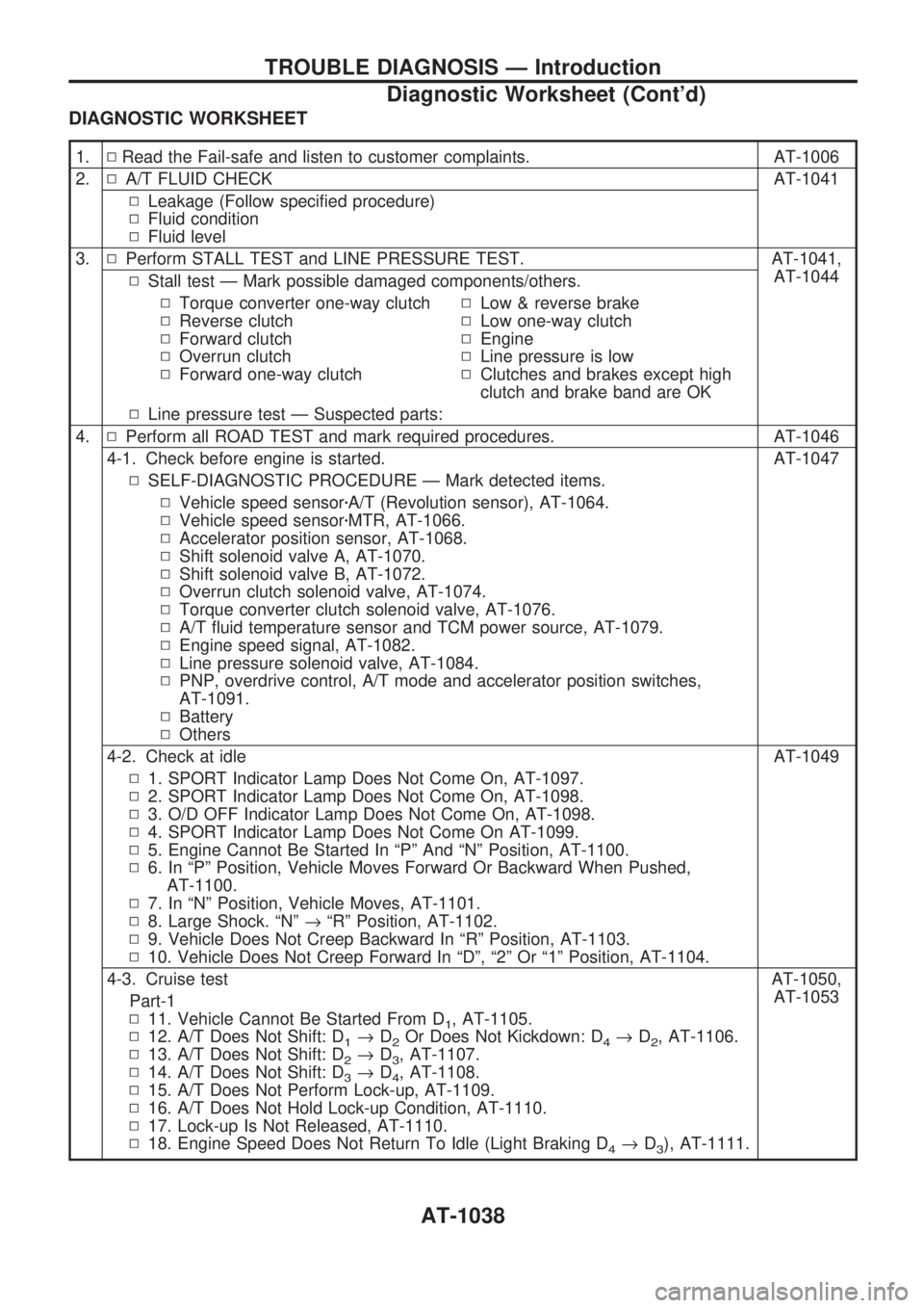
DIAGNOSTIC WORKSHEET
1.NRead the Fail-safe and listen to customer complaints. AT-1006
2.NA/T FLUID CHECK AT-1041
NLeakage (Follow specified procedure)
NFluid condition
NFluid level
3.NPerform STALL TEST and LINE PRESSURE TEST. AT-1041,
AT-1044
NStall test Ð Mark possible damaged components/others.
NTorque converter one-way clutch
NReverse clutch
NForward clutch
NOverrun clutch
NForward one-way clutchNLow & reverse brake
NLow one-way clutch
NEngine
NLine pressure is low
NClutches and brakes except high
clutch and brake band are OK
NLine pressure test Ð Suspected parts:
4.NPerform all ROAD TEST and mark required procedures. AT-1046
4-1. Check before engine is started. AT-1047
NSELF-DIAGNOSTIC PROCEDURE Ð Mark detected items.
NVehicle speed sensorzA/T (Revolution sensor), AT-1064.
NVehicle speed sensorzMTR, AT-1066.
NAccelerator position sensor, AT-1068.
NShift solenoid valve A, AT-1070.
NShift solenoid valve B, AT-1072.
NOverrun clutch solenoid valve, AT-1074.
NTorque converter clutch solenoid valve, AT-1076.
NA/T fluid temperature sensor and TCM power source, AT-1079.
NEngine speed signal, AT-1082.
NLine pressure solenoid valve, AT-1084.
NPNP, overdrive control, A/T mode and accelerator position switches,
AT-1091.
NBattery
NOthers
4-2. Check at idle AT-1049
N1. SPORT Indicator Lamp Does Not Come On, AT-1097.
N2. SPORT Indicator Lamp Does Not Come On, AT-1098.
N3. O/D OFF Indicator Lamp Does Not Come On, AT-1098.
N4. SPORT Indicator Lamp Does Not Come On AT-1099.
N5. Engine Cannot Be Started In ªPº And ªNº Position, AT-1100.
N6. In ªPº Position, Vehicle Moves Forward Or Backward When Pushed,
AT-1100.
N7. In ªNº Position, Vehicle Moves, AT-1101.
N8. Large Shock. ªNº®ªRº Position, AT-1102.
N9. Vehicle Does Not Creep Backward In ªRº Position, AT-1103.
N10. Vehicle Does Not Creep Forward In ªDº, ª2º Or ª1º Position, AT-1104.
4-3. Cruise test AT-1050,
AT-1053
Part-1
N11. Vehicle Cannot Be Started From D
1, AT-1105.
N12. A/T Does Not Shift: D
1®D2Or Does Not Kickdown: D4®D2, AT-1106.
N13. A/T Does Not Shift: D
2®D3, AT-1107.
N14. A/T Does Not Shift: D
3®D4, AT-1108.
N15. A/T Does Not Perform Lock-up, AT-1109.
N16. A/T Does Not Hold Lock-up Condition, AT-1110.
N17. Lock-up Is Not Released, AT-1110.
N18. Engine Speed Does Not Return To Idle (Light Braking D
4®D3), AT-1111.
TROUBLE DIAGNOSIS Ð Introduction
Diagnostic Worksheet (Cont'd)
AT-1038
Page 41 of 1033
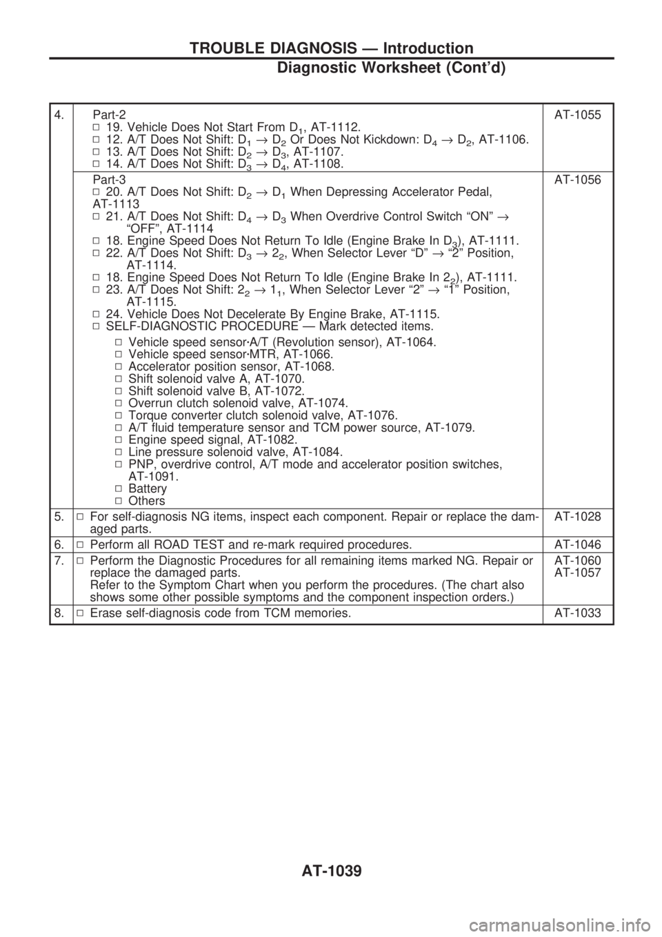
4. Part-2
N19. Vehicle Does Not Start From D
1, AT-1112.
N12. A/T Does Not Shift: D
1®D2Or Does Not Kickdown: D4®D2, AT-1106.
N13. A/T Does Not Shift: D
2®D3, AT-1107.
N14. A/T Does Not Shift: D
3®D4, AT-1108.AT-1055
Part-3
N20. A/T Does Not Shift: D
2®D1When Depressing Accelerator Pedal,
AT-1113
N21. A/T Does Not Shift: D
4®D3When Overdrive Control Switch ªONº®
ªOFFº, AT-1114
N18. Engine Speed Does Not Return To Idle (Engine Brake In D
3), AT-1111.
N22. A/T Does Not Shift: D
3®22, When Selector Lever ªDº®ª2º Position,
AT-1114.
N18. Engine Speed Does Not Return To Idle (Engine Brake In 2
2), AT-1111.
N23. A/T Does Not Shift: 2
2®11, When Selector Lever ª2º®ª1º Position,
AT-1115.
N24. Vehicle Does Not Decelerate By Engine Brake, AT-1115.
NSELF-DIAGNOSTIC PROCEDURE Ð Mark detected items.AT-1056
NVehicle speed sensorzA/T (Revolution sensor), AT-1064.
NVehicle speed sensorzMTR, AT-1066.
NAccelerator position sensor, AT-1068.
NShift solenoid valve A, AT-1070.
NShift solenoid valve B, AT-1072.
NOverrun clutch solenoid valve, AT-1074.
NTorque converter clutch solenoid valve, AT-1076.
NA/T fluid temperature sensor and TCM power source, AT-1079.
NEngine speed signal, AT-1082.
NLine pressure solenoid valve, AT-1084.
NPNP, overdrive control, A/T mode and accelerator position switches,
AT-1091.
NBattery
NOthers
5.NFor self-diagnosis NG items, inspect each component. Repair or replace the dam-
aged parts.AT-1028
6.NPerform all ROAD TEST and re-mark required procedures. AT-1046
7.NPerform the Diagnostic Procedures for all remaining items marked NG. Repair or
replace the damaged parts.
Refer to the Symptom Chart when you perform the procedures. (The chart also
shows some other possible symptoms and the component inspection orders.)AT-1060
AT-1057
8.NErase self-diagnosis code from TCM memories. AT-1033
TROUBLE DIAGNOSIS Ð Introduction
Diagnostic Worksheet (Cont'd)
AT-1039
Page 71 of 1033
![NISSAN PATROL 2000 Electronic Repair Manual DIAGNOSTIC PROCEDURE
Perform diagnostic test mode II (self-
diagnostic results) for engine control.
Refer to EC section [ªMalfunction Indica-
tor (MI)º, ªON BOARD DIAGNOSTIC
SYSTEM DESCRIPTIONº].
NISSAN PATROL 2000 Electronic Repair Manual DIAGNOSTIC PROCEDURE
Perform diagnostic test mode II (self-
diagnostic results) for engine control.
Refer to EC section [ªMalfunction Indica-
tor (MI)º, ªON BOARD DIAGNOSTIC
SYSTEM DESCRIPTIONº].](/manual-img/5/57367/w960_57367-70.png)
DIAGNOSTIC PROCEDURE
Perform diagnostic test mode II (self-
diagnostic results) for engine control.
Refer to EC section [ªMalfunction Indica-
tor (MI)º, ªON BOARD DIAGNOSTIC
SYSTEM DESCRIPTIONº].
OK
cNG
Check accelerator position
sensor circuit for engine
control. Refer to EC sec-
tion [ªTROUBLE DIAGNO-
SIS FOR ªTHRTL
(ACCEL) POSI SENº
(DTC 43)].
CHECK INPUT SIGNAL.
1. Turn ignition switch to ªONº
position.
(Do not start engine.)
2. Select ªTCM INPUT SIGNALSº
in Data Monitor.
3. Read out the value of ªTHRTL
POS SENº.
Voltage:
Fully-closed throttle:
Approximately 0.5V
Fully-open throttle:
Approximately 4V
------------------------------------------------------------------------------------------------------------------------------------OR------------------------------------------------------------------------------------------------------------------------------------
1. Turn ignition switch to ªONº
position. (Do not start engine.)
2. Check voltage between TCM
terminals
V41andV42while
accelerator pedal is depressed
slowly.
Voltage:
Fully-closed throttle valve:
Approximately 0.5 - 0.7V
Fully-open throttle valve:
Approximately 4V
(Voltage rises gradually in
response to throttle position)
OK
cNG
Check harness for short or
open between ECM and
TCM regarding accelerator
position sensor circuit.
(Main harness)
CHECK ACCELERATOR POSITION
SWITCH.
Refer to ªCHECK ACCELERATOR POSI-
TION SWITCHº, AT-1091.
OK
cNG
Repair or replace dam-
aged parts.
Perform ªSELF-DIAGNOSIS CODE CON-
FIRMATION PROCEDUREº, AT-1068.
OK
cNG
1. Perform TCM input/
output signal inspection.
2. If NG, recheck TCM pin
terminals for damage or
loose connection with
harness connector.
INSPECTION END
SAT738J
SAT239J
.
.
.
.
TROUBLE DIAGNOSIS FOR THROTTLE POSI SEN
Accelerator Position Sensor (Cont'd)
AT-1069
Page 72 of 1033
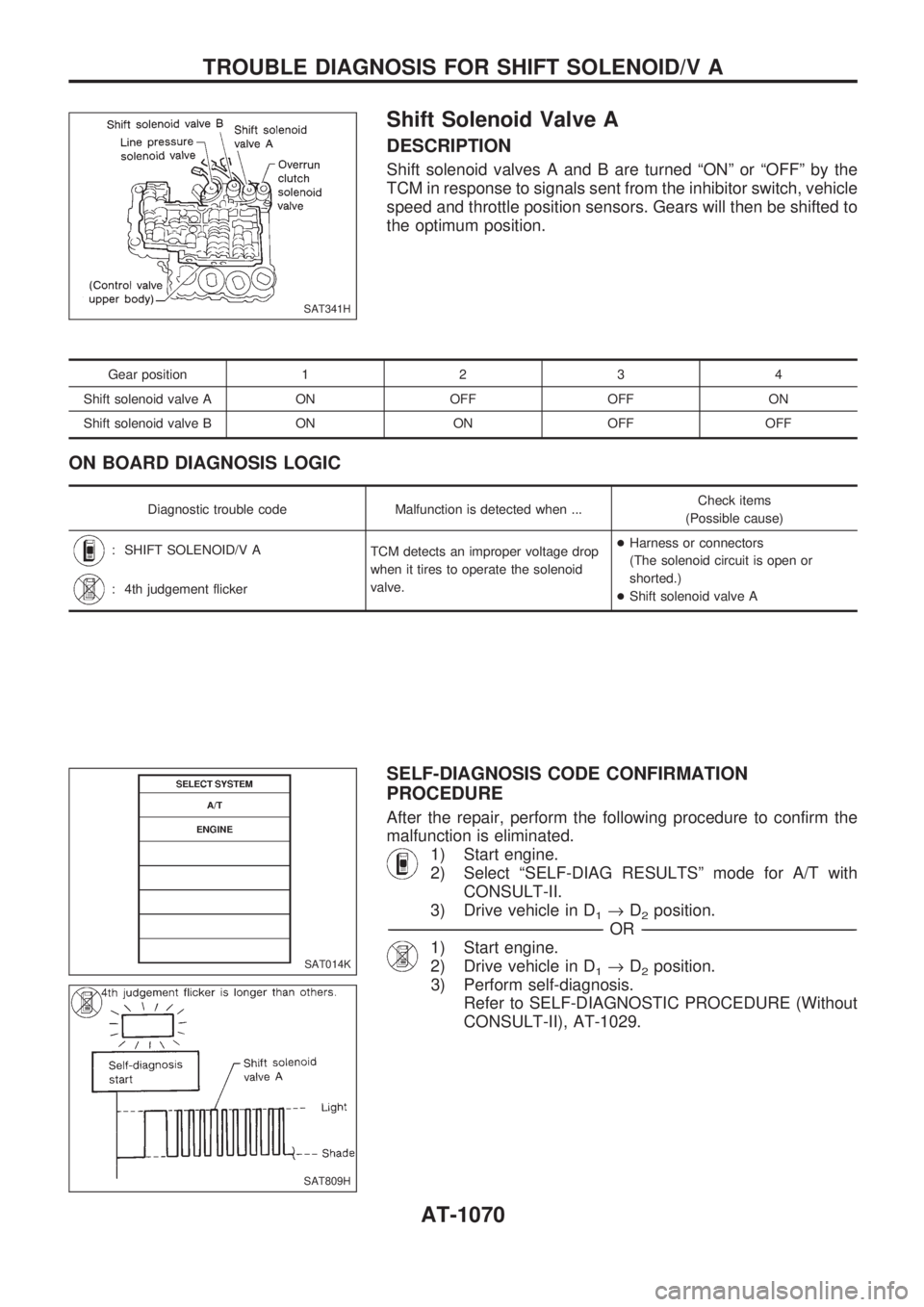
Shift Solenoid Valve A
DESCRIPTION
Shift solenoid valves A and B are turned ªONº or ªOFFº by the
TCM in response to signals sent from the inhibitor switch, vehicle
speed and throttle position sensors. Gears will then be shifted to
the optimum position.
Gear position1234
Shift solenoid valve A ON OFF OFF ON
Shift solenoid valve B ON ON OFF OFF
ON BOARD DIAGNOSIS LOGIC
Diagnostic trouble code Malfunction is detected when ...Check items
(Possible cause)
: SHIFT SOLENOID/V A
TCM detects an improper voltage drop
when it tires to operate the solenoid
valve.+Harness or connectors
(The solenoid circuit is open or
shorted.)
+Shift solenoid valve A
: 4th judgement flicker
SELF-DIAGNOSIS CODE CONFIRMATION
PROCEDURE
After the repair, perform the following procedure to confirm the
malfunction is eliminated.
1) Start engine.
2) Select ªSELF-DIAG RESULTSº mode for A/T with
CONSULT-II.
3) Drive vehicle in D
1®D2position.
-------------------------------------------------------------------------------------------------------------------------------------------------------------------------------------------------------------------------------------------------OR-------------------------------------------------------------------------------------------------------------------------------------------------------------------------------------------------------------------------------------------------
1) Start engine.
2) Drive vehicle in D
1®D2position.
3) Perform self-diagnosis.
Refer to SELF-DIAGNOSTIC PROCEDURE (Without
CONSULT-II), AT-1029.
SAT341H
SAT014K
SAT809H
TROUBLE DIAGNOSIS FOR SHIFT SOLENOID/V A
AT-1070
Page 73 of 1033
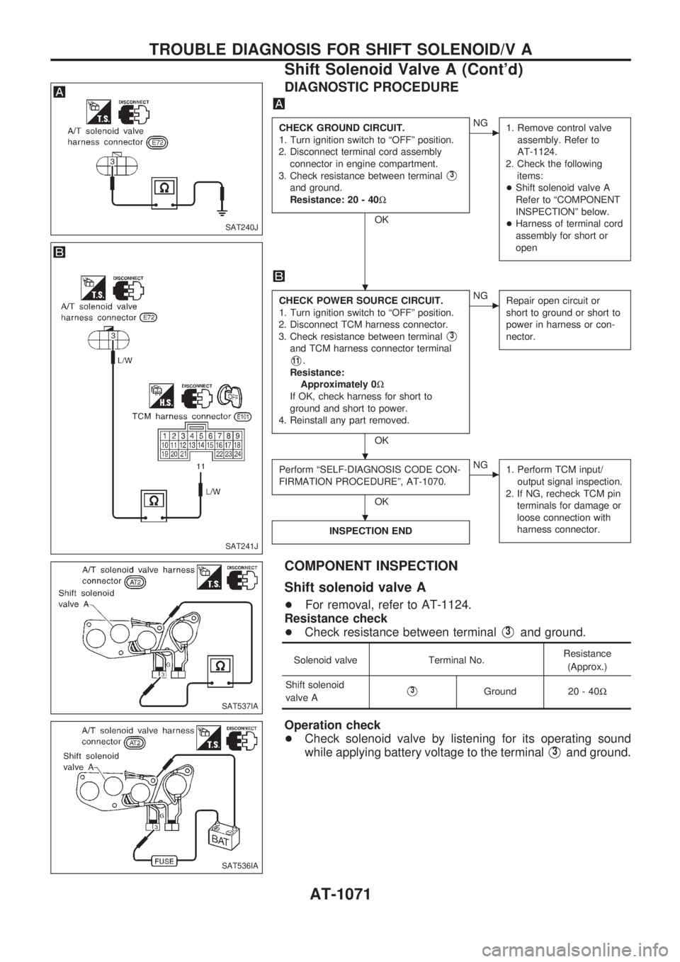
DIAGNOSTIC PROCEDURE
CHECK GROUND CIRCUIT.
1. Turn ignition switch to ªOFFº position.
2. Disconnect terminal cord assembly
connector in engine compartment.
3. Check resistance between terminal
V3
and ground.
Resistance: 20 - 40W
OK
cNG
1. Remove control valve
assembly. Refer to
AT-1124.
2. Check the following
items:
+Shift solenoid valve A
Refer to ªCOMPONENT
INSPECTIONº below.
+Harness of terminal cord
assembly for short or
open
CHECK POWER SOURCE CIRCUIT.
1. Turn ignition switch to ªOFFº position.
2. Disconnect TCM harness connector.
3. Check resistance between terminal
V3
and TCM harness connector terminal
V11.
Resistance:
Approximately 0W
If OK, check harness for short to
ground and short to power.
4. Reinstall any part removed.
OK
cNG
Repair open circuit or
short to ground or short to
power in harness or con-
nector.
Perform ªSELF-DIAGNOSIS CODE CON-
FIRMATION PROCEDUREº, AT-1070.
OK
cNG
1. Perform TCM input/
output signal inspection.
2. If NG, recheck TCM pin
terminals for damage or
loose connection with
harness connector.
INSPECTION END
COMPONENT INSPECTION
Shift solenoid valve A
+For removal, refer to AT-1124.
Resistance check
+Check resistance between terminal
V3and ground.
Solenoid valve Terminal No.Resistance
(Approx.)
Shift solenoid
valve A
V3Ground 20 - 40W
Operation check
+Check solenoid valve by listening for its operating sound
while applying battery voltage to the terminal
V3and ground.
SAT240J
SAT241J
SAT537IA
SAT536IA
.
.
.
TROUBLE DIAGNOSIS FOR SHIFT SOLENOID/V A
Shift Solenoid Valve A (Cont'd)
AT-1071
Page 74 of 1033
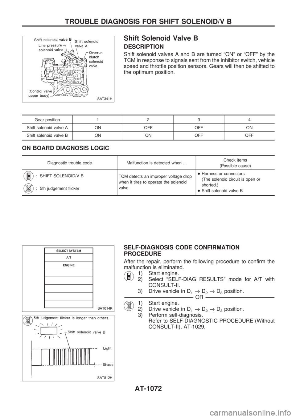
Shift Solenoid Valve B
DESCRIPTION
Shift solenoid valves A and B are turned ªONº or ªOFFº by the
TCM in response to signals sent from the inhibitor switch, vehicle
speed and throttle position sensors. Gears will then be shifted to
the optimum position.
Gear position1234
Shift solenoid valve A ON OFF OFF ON
Shift solenoid valve B ON ON OFF OFF
ON BOARD DIAGNOSIS LOGIC
Diagnostic trouble code Malfunction is detected when ...Check items
(Possible cause)
: SHIFT SOLENOID/V B
TCM detects an improper voltage drop
when it tires to operate the solenoid
valve.+Harness or connectors
(The solenoid circuit is open or
shorted.)
+Shift solenoid valve B
: 5th judgement flicker
SELF-DIAGNOSIS CODE CONFIRMATION
PROCEDURE
After the repair, perform the following procedure to confirm the
malfunction is eliminated.
1) Start engine.
2) Select ªSELF-DIAG RESULTSº mode for A/T with
CONSULT-II.
3) Drive vehicle in D
1®D2®D3position.
-------------------------------------------------------------------------------------------------------------------------------------------------------------------------------------------------------------------------------------------------OR-------------------------------------------------------------------------------------------------------------------------------------------------------------------------------------------------------------------------------------------------
1) Start engine.
2) Drive vehicle in D
1®D2®D3position.
3) Perform self-diagnosis.
Refer to SELF-DIAGNOSTIC PROCEDURE (Without
CONSULT-II), AT-1029.
SAT341H
SAT014K
SAT812H
TROUBLE DIAGNOSIS FOR SHIFT SOLENOID/V B
AT-1072
Page 75 of 1033
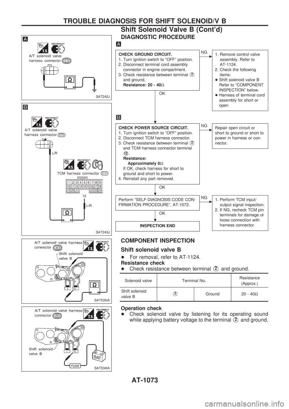
DIAGNOSTIC PROCEDURE
CHECK GROUND CIRCUIT.
1. Turn ignition switch to ªOFFº position.
2. Disconnect terminal cord assembly
connector in engine compartment.
3. Check resistance between terminal
V2
and ground.
Resistance: 20 - 40W
OK
cNG
1. Remove control valve
assembly. Refer to
AT-1124.
2. Check the following
items:
+Shift solenoid valve B
Refer to ªCOMPONENT
INSPECTIONº below.
+Harness of terminal cord
assembly for short or
open
CHECK POWER SOURCE CIRCUIT.
1. Turn ignition switch to ªOFFº position.
2. Disconnect TCM harness connector.
3. Check resistance between terminal
V2
and TCM harness connector terminal
V12.
Resistance:
Approximately 0W
If OK, check harness for short to
ground and short to power.
4. Reinstall any part removed.
OK
cNG
Repair open circuit or
short to ground or short to
power in harness or con-
nector.
Perform ªSELF-DIAGNOSIS CODE CON-
FIRMATION PROCEDUREº, AT-1072.
OK
cNG
1. Perform TCM input/
output signal inspection.
2. If NG, recheck TCM pin
terminals for damage or
loose connection with
harness connector.
INSPECTION END
COMPONENT INSPECTION
Shift solenoid valve B
+For removal, refer to AT-1124.
Resistance check
+Check resistance between terminal
V2and ground.
Solenoid valve Terminal No.Resistance
(Approx.)
Shift solenoid
valve B
V2Ground 20 - 40W
Operation check
+Check solenoid valve by listening for its operating sound
while applying battery voltage to the terminal
V2and ground.
SAT242J
SAT243J
SAT535IA
SAT534IA
.
.
.
TROUBLE DIAGNOSIS FOR SHIFT SOLENOID/V B
Shift Solenoid Valve B (Cont'd)
AT-1073