2000 NISSAN PATROL power steering
[x] Cancel search: power steeringPage 260 of 1033
REMOVAL
1. Remove the following:
+Engine coolant draining
+Charge air cooler
+Air inlet pipe
+Throttle body
+Rocker cover
+Oil level gauge guide
+EGR guide tube
+EGR volume control solenoid valve
+Fuel hose
+Injection tube
+Radiator upper hose
+Radiator shroud
+Cooling fan
+Drive belt
+Vacuum pipe
+Vacuum pump
2. Move the power steering pump.
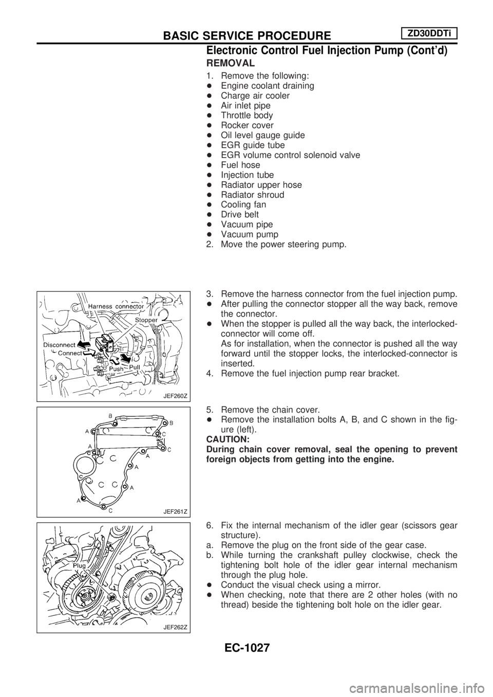
3. Remove the harness connector from the fuel injection pump.
+After pulling the connector stopper all the way back, remove
the connector.
+When the stopper is pulled all the way back, the interlocked-
connector will come off.
As for installation, when the connector is pushed all the way
forward until the stopper locks, the interlocked-connector is
inserted.
4. Remove the fuel injection pump rear bracket.
5. Remove the chain cover.
+Remove the installation bolts A, B, and C shown in the fig-
ure (left).
CAUTION:
During chain cover removal, seal the opening to prevent
foreign objects from getting into the engine.
6. Fix the internal mechanism of the idler gear (scissors gear
structure).
a. Remove the plug on the front side of the gear case.
b. While turning the crankshaft pulley clockwise, check the
tightening bolt hole of the idler gear internal mechanism
through the plug hole.
+Conduct the visual check using a mirror.
+When checking, note that there are 2 other holes (with no
thread) beside the tightening bolt hole on the idler gear.
JEF260Z
JEF261Z
JEF262Z
BASIC SERVICE PROCEDUREZD30DDTi
Electronic Control Fuel Injection Pump (Cont'd)
EC-1027
Page 511 of 1033
ELECTRICAL SYSTEM
SECTION
EL
When you read wiring diagrams:
+Read GI section, ªHOW TO READ WIRING DIAGRAMSº.
When you perform trouble diagnoses, read GI section, ªHOW TO FOLLOW FLOW
CHART IN TROUBLE DIAGNOSESº and ªHOW TO PERFORM EFFICIENT DIAGNOSIS
FOR AN ELECTRICAL INCIDENTº.
+Check for any service bulletins before servicing the vehicle.
MODIFICATION NOTICE:
+Power window (driver's side only) with an interruption detection function has been adopted.
+ID code entry procedure of multi-remote control system has been changed.
+NATS (Nissan Anti-Theft System) has been adopted on ZD engine model.
CONTENTS
PRECAUTIONS AND PREPARATION............... 1003
Supplemental Restraint System (SRS) ªAIR
BAGº and ªSEAT BELT PRE-TENSIONERº ... 1003
POWER SUPPLY ROUTING............................... 1004
Schematic ........................................................ 1004
Wiring Diagram Ð POWER Ð ........................ 1005
GROUND DISTRIBUTION/LHD MODELS.......... 1013
Engine Room Harness..................................... 1013
Engine Control Harness................................... 1016
Main Harness ................................................... 1017
Body Harness .................................................. 1020
Body No. 2 Harness ........................................ 1022
Back Door and Rear Window Defogger
Harness ............................................................ 1023
GROUND DISTRIBUTION/RHD MODELS......... 1024
Engine Room Harness..................................... 1024
Engine Control Harness................................... 1027
Main Harness ................................................... 1028
Body Harness .................................................. 1031
Body No. 2 Harness ........................................ 1033
Back Door and Rear Window Defogger
Harness ............................................................ 1034
BATTERY............................................................. 1035
Service Data and Specifications (SDS) ........... 1035
STARTING SYSTEM........................................... 1036
Wiring Diagram Ð START Ð/M/T Models...... 1036
Wiring Diagram Ð START Ð/A/T Models ...... 1037
Construction ..................................................... 1038Service Data and Specifications (SDS) ........... 1039
CHARGING SYSTEM.......................................... 1040
Wiring Diagram Ð CHARGE ........................... 1040
Construction ..................................................... 1041
Service Data and Specifications (SDS) ........... 1041
COMBINATION SWITCH.................................... 1042
Check ............................................................... 1042
STEERING SWITCH............................................ 1043
Check ............................................................... 1043
HEADLAMP Ð Daytime Light System Ð........ 1044
Wiring Diagram Ð DTRL Ð ............................ 1044
PARKING, LICENSE AND TAIL LAMPS........... 1046
Wiring Diagram Ð TAIL/L Ð/LHD Models ...... 1046
Wiring Diagram Ð TAIL/L Ð/RHD Models ..... 1048
STOP LAMP........................................................ 1050
Wiring Diagram Ð STOP/L Ð......................... 1050
BACK-UP LAMP.................................................. 1051
Wiring Diagram Ð BACK/L Ð/RHD Models ... 1051
FRONT FOG LAMP............................................. 1052
Wiring Diagram Ð F/FOG Ð .......................... 1052
REAR FOG LAMP............................................... 1053
Wiring Diagram Ð R/FOG Ð .......................... 1053
CORNERING LAMP............................................ 1054
Wiring Diagram Ð CORNER Ð/LHD Models . 1054
System Description/RHD Models .................... 1055
Wiring Diagram Ð CORNER Ð/RHD Models1056
Trouble Diagnoses/RHD Models ..................... 1057
EL
Page 766 of 1033
+Vacuum pipe
+Vacuum pump
2. Move the following parts.
+TDC sensor harness
+Power steering oil pump
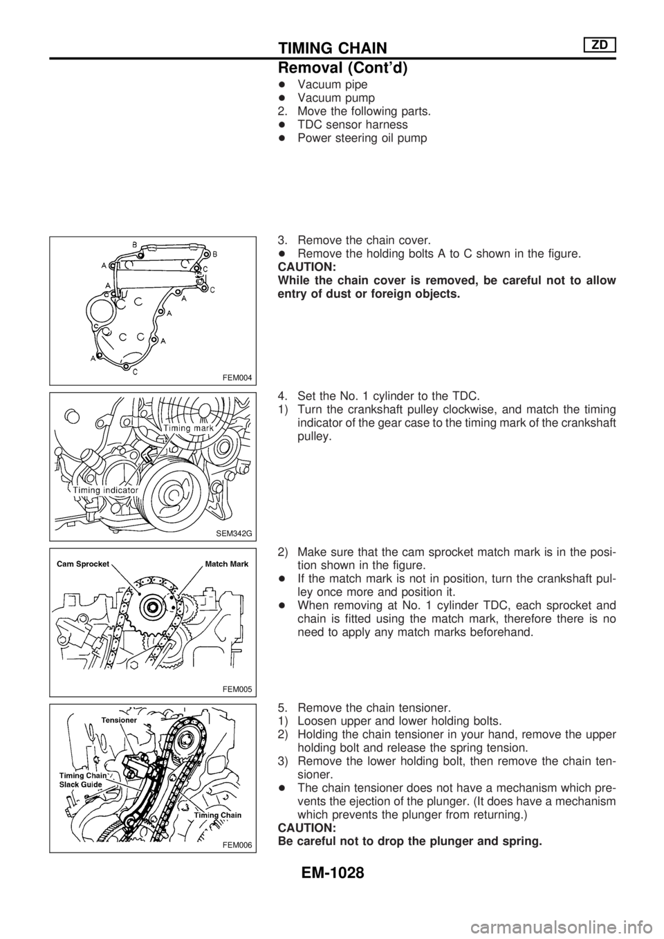
3. Remove the chain cover.
+Remove the holding bolts A to C shown in the figure.
CAUTION:
While the chain cover is removed, be careful not to allow
entry of dust or foreign objects.
4. Set the No. 1 cylinder to the TDC.
1) Turn the crankshaft pulley clockwise, and match the timing
indicator of the gear case to the timing mark of the crankshaft
pulley.
2) Make sure that the cam sprocket match mark is in the posi-
tion shown in the figure.
+If the match mark is not in position, turn the crankshaft pul-
ley once more and position it.
+When removing at No. 1 cylinder TDC, each sprocket and
chain is fitted using the match mark, therefore there is no
need to apply any match marks beforehand.
5. Remove the chain tensioner.
1) Loosen upper and lower holding bolts.
2) Holding the chain tensioner in your hand, remove the upper
holding bolt and release the spring tension.
3) Remove the lower holding bolt, then remove the chain ten-
sioner.
+The chain tensioner does not have a mechanism which pre-
vents the ejection of the plunger. (It does have a mechanism
which prevents the plunger from returning.)
CAUTION:
Be careful not to drop the plunger and spring.
FEM004
SEM342G
FEM005
FEM006
TIMING CHAINZD
Removal (Cont'd)
EM-1028
Page 803 of 1033
5. Disconnect harness connectors from alternator and air com-
pressor.
6. Remove alternator.
7. After removing refrigerant, remove pipes of air compressor
and inlet/outlet.
8. Disconnect heating hose, install blank cap to hose to prevent
coolant from leaking.
9. Remove heating pipe.
10. Remove heat insulator.
11. Remove catalytic converter.
Engine room (Right)
12. Remove power steering reservoir tank from bracket, and fix
it to the vehicle with a rope.
CAUTION:
Keep the reservoir tank level when fixing to prevent oil leak.
13. Remove fuel feed and return hoses.
CAUTION:
Install blank caps immediately to avoid fuel leakage.
14. Remove all harness connectors on the engine, and move
harnesses to the side of the vehicle.
Vehicle underfloor
15. Remove starter motor.
16. Detach A/T oil cooler pipes from oil pan. (A/T model)
17. Remove rear propeller shaft.
18. Remove mounting bolts to secure the engine to transmission.
1) Remove torque converter installation bolt. (A/T model)
2) Lift transmission bottom with transmission jack, and remove
rear mount members from the vehicle.
3) Lower transmission with the jack, and remove upper mount-
ing bolts securing the engine to transmission.
4) Lift transmission with the jack, and reinstall rear mount mem-
bers to the vehicle.
5) Position the jack to the front side of transmission.
6) Remove remaining mounting bolts securing the engine to
transmission.
Removal operation
19. Remove air conditioner high pressure pipes at the rear of the
engine room.
+This is due to some inconvenience in the rear slinger instal-
lation.
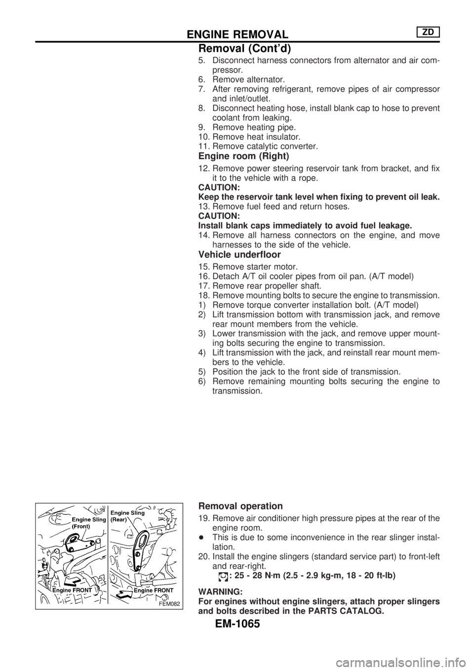
20. Install the engine slingers (standard service part) to front-left
and rear-right.
:25-28Nzm (2.5 - 2.9 kg-m, 18 - 20 ft-lb)
WARNING:
For engines without engine slingers, attach proper slingers
and bolts described in the PARTS CATALOG.
FEM082
ENGINE REMOVALZD
Removal (Cont'd)
EM-1065
Page 882 of 1033
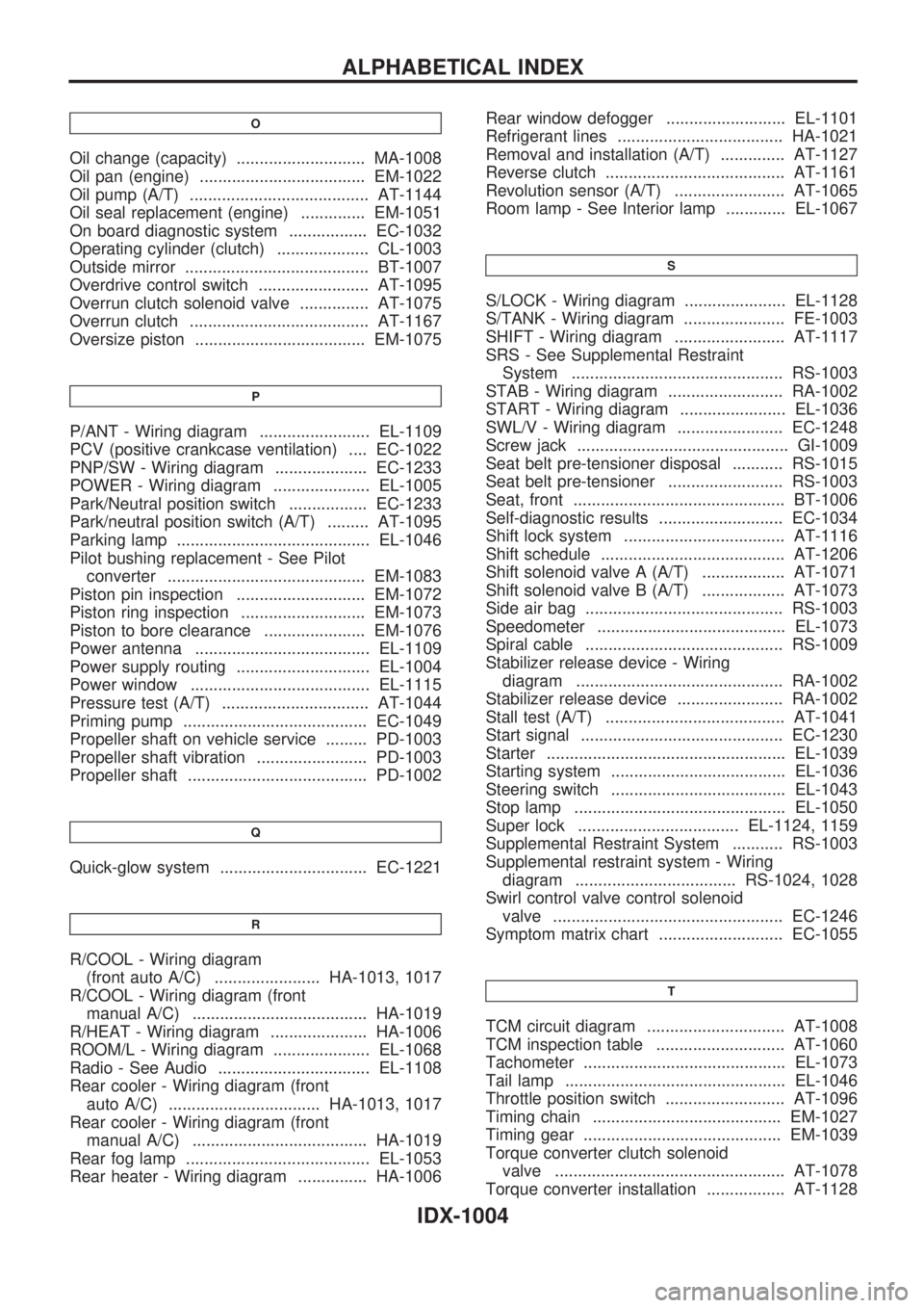
O
Oil change (capacity) ............................ MA-1008
Oil pan (engine) .................................... EM-1022
Oil pump (A/T) ....................................... AT-1144
Oil seal replacement (engine) .............. EM-1051
On board diagnostic system ................. EC-1032
Operating cylinder (clutch) .................... CL-1003
Outside mirror ........................................ BT-1007
Overdrive control switch ........................ AT-1095
Overrun clutch solenoid valve ............... AT-1075
Overrun clutch ....................................... AT-1167
Oversize piston ..................................... EM-1075
P
P/ANT - Wiring diagram ........................ EL-1109
PCV (positive crankcase ventilation) .... EC-1022
PNP/SW - Wiring diagram .................... EC-1233
POWER - Wiring diagram ..................... EL-1005
Park/Neutral position switch ................. EC-1233
Park/neutral position switch (A/T) ......... AT-1095
Parking lamp .......................................... EL-1046
Pilot bushing replacement - See Pilot
converter ........................................... EM-1083
Piston pin inspection ............................ EM-1072
Piston ring inspection ........................... EM-1073
Piston to bore clearance ...................... EM-1076
Power antenna ...................................... EL-1109
Power supply routing ............................. EL-1004
Power window ....................................... EL-1115
Pressure test (A/T) ................................ AT-1044
Priming pump ........................................ EC-1049
Propeller shaft on vehicle service ......... PD-1003
Propeller shaft vibration ........................ PD-1003
Propeller shaft ....................................... PD-1002
Q
Quick-glow system ................................ EC-1221
R
R/COOL - Wiring diagram
(front auto A/C) ....................... HA-1013, 1017
R/COOL - Wiring diagram (front
manual A/C) ...................................... HA-1019
R/HEAT - Wiring diagram ..................... HA-1006
ROOM/L - Wiring diagram ..................... EL-1068
Radio - See Audio ................................. EL-1108
Rear cooler - Wiring diagram (front
auto A/C) ................................. HA-1013, 1017
Rear cooler - Wiring diagram (front
manual A/C) ...................................... HA-1019
Rear fog lamp ........................................ EL-1053
Rear heater - Wiring diagram ............... HA-1006Rear window defogger .......................... EL-1101
Refrigerant lines .................................... HA-1021
Removal and installation (A/T) .............. AT-1127
Reverse clutch ....................................... AT-1161
Revolution sensor (A/T) ........................ AT-1065
Room lamp - See Interior lamp ............. EL-1067
S
S/LOCK - Wiring diagram ...................... EL-1128
S/TANK - Wiring diagram ...................... FE-1003
SHIFT - Wiring diagram ........................ AT-1117
SRS - See Supplemental Restraint
System .............................................. RS-1003
STAB - Wiring diagram ......................... RA-1002
START - Wiring diagram ....................... EL-1036
SWL/V - Wiring diagram ....................... EC-1248
Screw jack .............................................. GI-1009
Seat belt pre-tensioner disposal ........... RS-1015
Seat belt pre-tensioner ......................... RS-1003
Seat, front .............................................. BT-1006
Self-diagnostic results ........................... EC-1034
Shift lock system ................................... AT-1116
Shift schedule ........................................ AT-1206
Shift solenoid valve A (A/T) .................. AT-1071
Shift solenoid valve B (A/T) .................. AT-1073
Side air bag ........................................... RS-1003
Speedometer ......................................... EL-1073
Spiral cable ........................................... RS-1009
Stabilizer release device - Wiring
diagram ............................................. RA-1002
Stabilizer release device ....................... RA-1002
Stall test (A/T) ....................................... AT-1041
Start signal ............................................ EC-1230
Starter .................................................... EL-1039
Starting system ...................................... EL-1036
Steering switch ...................................... EL-1043
Stop lamp .............................................. EL-1050
Super lock ................................... EL-1124, 1159
Supplemental Restraint System ........... RS-1003
Supplemental restraint system - Wiring
diagram ................................... RS-1024, 1028
Swirl control valve control solenoid
valve .................................................. EC-1246
Symptom matrix chart ........................... EC-1055
T
TCM circuit diagram .............................. AT-1008
TCM inspection table ............................ AT-1060
Tachometer ............................................ EL-1073
Tail lamp ................................................ EL-1046
Throttle position switch .......................... AT-1096
Timing chain ......................................... EM-1027
Timing gear ........................................... EM-1039
Torque converter clutch solenoid
valve .................................................. AT-1078
Torque converter installation ................. AT-1128
ALPHABETICAL INDEX
IDX-1004
Page 901 of 1033
![NISSAN PATROL 2000 Electronic Repair Manual Chassis and Body Maintenance
Abbreviations: R = Replace, I = Inspect: Correct or replace if necessary, L = Lubricate, T = Tighten, [ ] = At the specified mileage only
MAINTENANCE OPERATIONMAINTENANCE NISSAN PATROL 2000 Electronic Repair Manual Chassis and Body Maintenance
Abbreviations: R = Replace, I = Inspect: Correct or replace if necessary, L = Lubricate, T = Tighten, [ ] = At the specified mileage only
MAINTENANCE OPERATIONMAINTENANCE](/manual-img/5/57367/w960_57367-900.png)
Chassis and Body Maintenance
Abbreviations: R = Replace, I = Inspect: Correct or replace if necessary, L = Lubricate, T = Tighten, [ ] = At the specified mileage only
MAINTENANCE OPERATIONMAINTENANCE INTERVAL
Perform on a kilometer basis, but on an annual basis
when driving less than 15,000 km (9,000 miles) per
year.km x 1,000 15 30 45 60 75 90
(miles x 1,000) (9) (18) (27) (36) (45) (54)
Months 12 24 36 48 60 72
Underhood and under vehicleReference
pages
Headlamp aimingIIIIII Ð
When alignment (if necessary, balance & rotate wheels)IIIIII Ð
Brake pads, rotors & other brake componentsHIIIIII Ð
Foot brake, parking brake & clutch (for free play, stroke & operation)IIIIII Ð
Brake booster vacuum hoses, connections & check valve I I I Ð
Brake & clutch, systems and fluid (for level and leaks)IIIIII Ð
Brake fluidHRRRÐ
Power steering fluid and lines (for level and leaks)IIIIII Ð
Supplemental air bag systems See NOTE (1)RS-1007
Ventilation air filterHRRRÐ
Manual transmission oil (Inspect for leaks. Replace if leaks are found.)IIIII[R] Ð
Automatic transmission fluid (for level and leaks)HIIIIII Ð
Greasing point of propeller shaft See NOTE (2)LLLLLL Ð
Transfer fluid and limited-slip differential (LSD) gear oil (for
level & leaks or replace)HSee NOTE (3) I I I R I I Ð
Drive shafts & steering damperHIIIIII Ð
Front wheel bearing greaseHIRIRIR Ð
Front axle joint in knuckle flangeLLLÐ
Free-running hub greaseHIIIIII Ð
Body mounting bolts & nutsTTTTTT Ð
Steering gear & linkage, axle & suspension parts, propeller shaft & exhaust systemHIIIIII Ð
Body corrosion See NOTE (4)Ð
NOTE: (1) Inspect after 10 years, then every 2 years.
(2) The propeller shaft should be re-greased after being immersed in water.
(3) Including differential gear with differential lock.
(4) Inspect once per year.
HMaintenance items with ªHº should be performed more frequently according to ªMaintenance under severe driv-
ing conditionsº.
PERIODIC MAINTENANCE
MA-1003
Page 904 of 1033
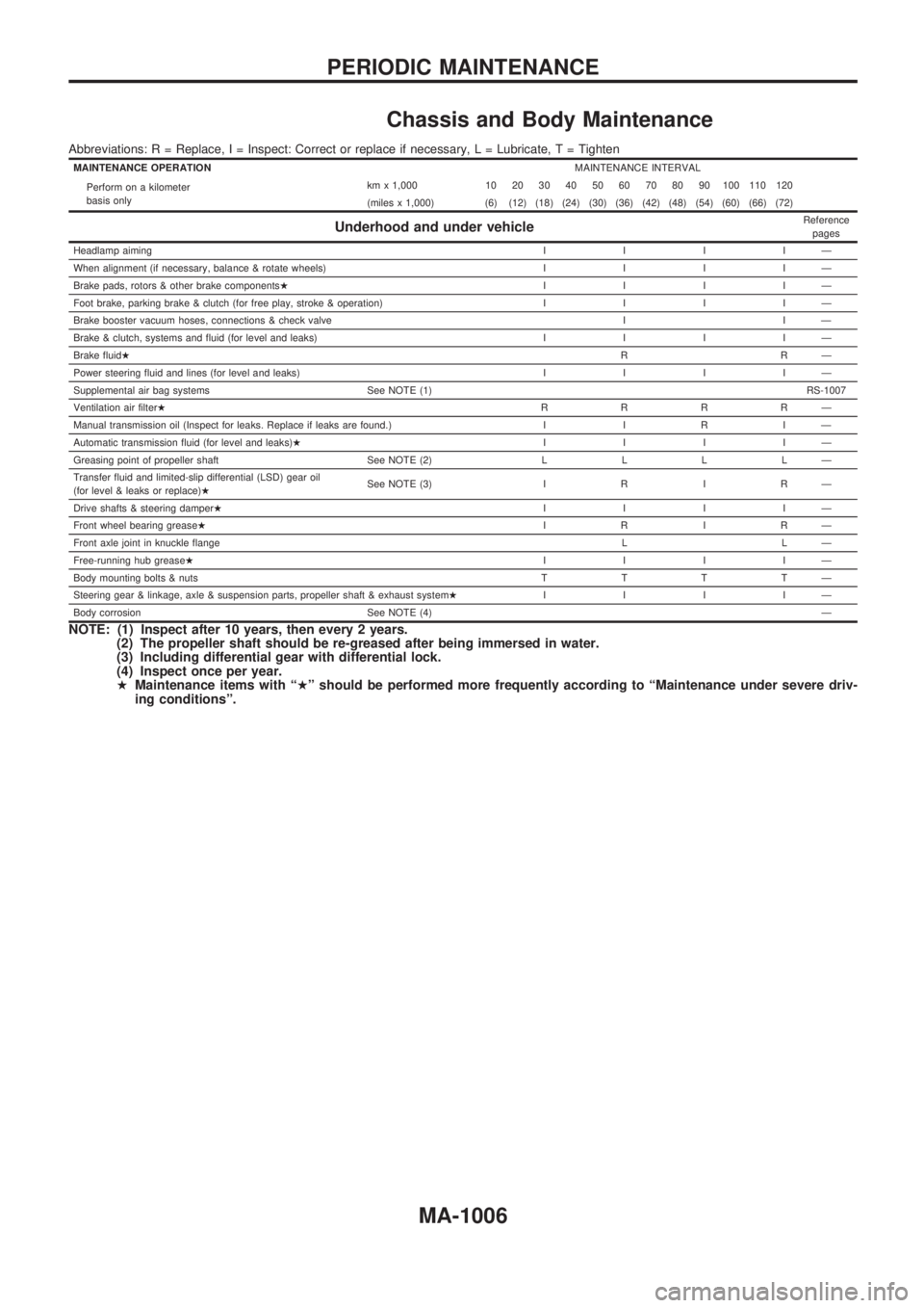
Chassis and Body Maintenance
Abbreviations: R = Replace, I = Inspect: Correct or replace if necessary, L = Lubricate, T = Tighten
MAINTENANCE OPERATIONMAINTENANCE INTERVAL
Perform on a kilometer
basis onlykm x 1,000 10 20 30 40 50 60 70 80 90 100 110 120
(miles x 1,000) (6) (12) (18) (24) (30) (36) (42) (48) (54) (60) (66) (72)
Underhood and under vehicleReference
pages
Headlamp aimingIIIIÐ
When alignment (if necessary, balance & rotate wheels)IIIIÐ
Brake pads, rotors & other brake componentsHIIIIÐ
Foot brake, parking brake & clutch (for free play, stroke & operation)IIIIÐ
Brake booster vacuum hoses, connections & check valve I I Ð
Brake & clutch, systems and fluid (for level and leaks)IIIIÐ
Brake fluidHRRÐ
Power steering fluid and lines (for level and leaks)IIIIÐ
Supplemental air bag systems See NOTE (1)RS-1007
Ventilation air filterHRRRRÐ
Manual transmission oil (Inspect for leaks. Replace if leaks are found.) I I R I Ð
Automatic transmission fluid (for level and leaks)HIIIIÐ
Greasing point of propeller shaft See NOTE (2)LLLLÐ
Transfer fluid and limited-slip differential (LSD) gear oil
(for level & leaks or replace)HSee NOTE (3) I R I R Ð
Drive shafts & steering damperHIIIIÐ
Front wheel bearing greaseHIRIRÐ
Front axle joint in knuckle flangeLLÐ
Free-running hub greaseHIIIIÐ
Body mounting bolts & nutsTTTTÐ
Steering gear & linkage, axle & suspension parts, propeller shaft & exhaust systemHIIIIÐ
Body corrosion See NOTE (4)Ð
NOTE: (1) Inspect after 10 years, then every 2 years.
(2) The propeller shaft should be re-greased after being immersed in water.
(3) Including differential gear with differential lock.
(4) Inspect once per year.
HMaintenance items with ªHº should be performed more frequently according to ªMaintenance under severe driv-
ing conditionsº.
PERIODIC MAINTENANCE
MA-1006
Page 906 of 1033
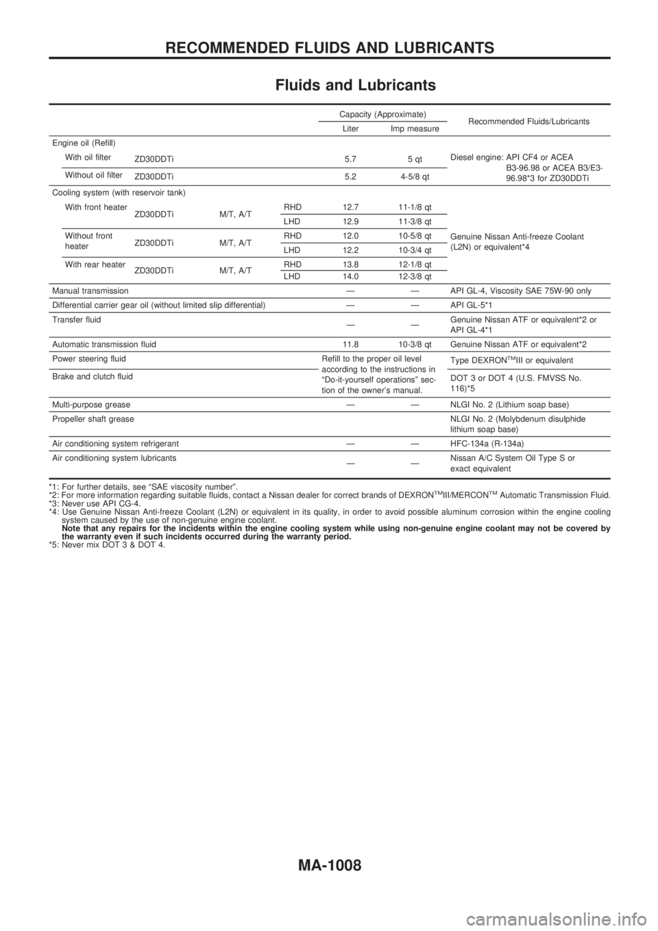
Fluids and Lubricants
Capacity (Approximate)
Recommended Fluids/Lubricants
Liter Imp measure
Engine oil (Refill)
With oil filter
ZD30DDTi 5.7 5 qtDiesel engine: API CF4 or ACEA
B3-96.98 or ACEA B3/E3-
96.98*3 for ZD30DDTi Without oil filter
ZD30DDTi 5.2 4-5/8 qt
Cooling system (with reservoir tank)
With front heater
ZD30DDTi M/T, A/TRHD 12.7 11-1/8 qt
Genuine Nissan Anti-freeze Coolant
(L2N) or equivalent*4 LHD 12.9 11-3/8 qt
Without front
heaterZD30DDTi M/T, A/TRHD 12.0 10-5/8 qt
LHD 12.2 10-3/4 qt
With rear heater
ZD30DDTi M/T, A/TRHD 13.8 12-1/8 qt
LHD 14.0 12-3/8 qt
Manual transmission Ð Ð API GL-4, Viscosity SAE 75W-90 only
Differential carrier gear oil (without limited slip differential) Ð Ð API GL-5*1
Transfer fluid
ÐÐGenuine Nissan ATF or equivalent*2 or
API GL-4*1
Automatic transmission fluid 11.8 10-3/8 qt Genuine Nissan ATF or equivalent*2
Power steering fluid Refill to the proper oil level
according to the instructions in
ªDo-it-yourself operationsº sec-
tion of the owner's manual.Type DEXRON
TMIII or equivalent
Brake and clutch fluid
DOT 3 or DOT 4 (U.S. FMVSS No.
116)*5
Multi-purpose grease Ð Ð NLGI No. 2 (Lithium soap base)
Propeller shaft greaseNLGI No. 2 (Molybdenum disulphide
lithium soap base)
Air conditioning system refrigerant Ð Ð HFC-134a (R-134a)
Air conditioning system lubricants
ÐÐNissan A/C System Oil Type S or
exact equivalent
*1: For further details, see ªSAE viscosity numberº.
*2: For more information regarding suitable fluids, contact a Nissan dealer for correct brands of DEXRON
TMIII/MERCONTMAutomatic Transmission Fluid.
*3: Never use API CG-4.
*4: Use Genuine Nissan Anti-freeze Coolant (L2N) or equivalent in its quality, in order to avoid possible aluminum corrosion within the engine cooling
system caused by the use of non-genuine engine coolant.
Note that any repairs for the incidents within the engine cooling system while using non-genuine engine coolant may not be covered by
the warranty even if such incidents occurred during the warranty period.
*5: Never mix DOT 3 & DOT 4.
RECOMMENDED FLUIDS AND LUBRICANTS
MA-1008