2000 NISSAN PATROL key battery
[x] Cancel search: key batteryPage 120 of 1033
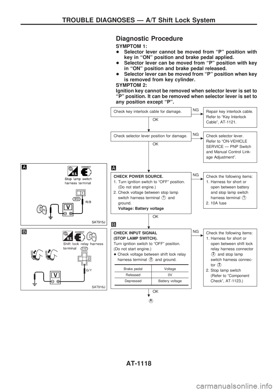
Diagnostic Procedure
SYMPTOM 1:
+Selector lever cannot be moved from ªPº position with
key in ªONº position and brake pedal applied.
+Selector lever can be moved from ªPº position with key
in ªONº position and brake pedal released.
+Selector lever can be moved from ªPº position when key
is removed from key cylinder.
SYMPTOM 2:
Ignition key cannot be removed when selector lever is set to
ªPº position. It can be removed when selector lever is set to
any position except ªPº.
Check key interlock cable for damage.
OK
cNG
Repair key interlock cable.
Refer to ªKey Interlock
Cableº, AT-1121.
Check selector lever position for damage.
OK
cNG
Check selector lever.
Refer to ªON-VEHICLE
SERVICE Ð PNP Switch
and Manual Control Link-
age Adjustmentº.
CHECK POWER SOURCE.
1. Turn ignition switch to ªOFFº position.
(Do not start engine.)
2. Check voltage between stop lamp
switch harness terminal
V1and
ground.
Voltage: Battery voltage
OK
cNG
Check the following items:
1. Harness for short or
open between battery
and stop lamp switch
harness terminal
V1
2. 10A fuse
CHECK INPUT SIGNAL
(STOP LAMP SWITCH).
Turn ignition switch to ªOFFº position.
(Do not start engine.)
+Check voltage between shift lock relay
harness terminal
V2and ground.
OK
cNG
Check the following items:
1. Harness for short or
open between shift lock
relay harness connector
V2and stop lamp
switch harness connec-
tor
V2
2. Stop lamp switch
(Refer to ªComponent
Checkº, AT-1123.)
VA
Brake pedal Voltage
Released 0V
Depressed Battery voltage
SAT915J
SAT916J
.
.
.
.
TROUBLE DIAGNOSES Ð A/T Shift Lock System
AT-1118
Page 124 of 1033
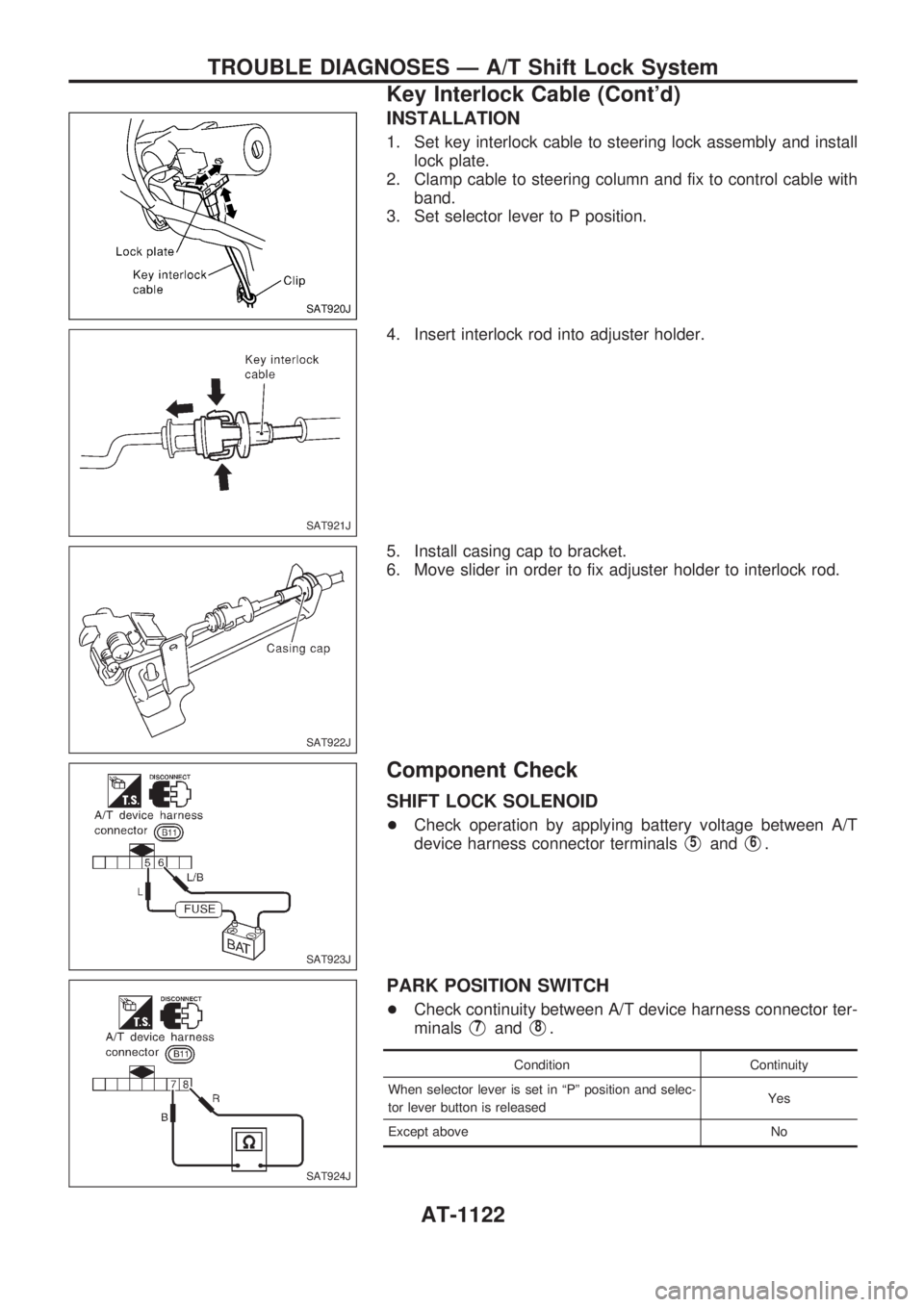
INSTALLATION
1. Set key interlock cable to steering lock assembly and install
lock plate.
2. Clamp cable to steering column and fix to control cable with
band.
3. Set selector lever to P position.
4. Insert interlock rod into adjuster holder.
5. Install casing cap to bracket.
6. Move slider in order to fix adjuster holder to interlock rod.
Component Check
SHIFT LOCK SOLENOID
+Check operation by applying battery voltage between A/T
device harness connector terminals
V5andV6.
PARK POSITION SWITCH
+Check continuity between A/T device harness connector ter-
minals
V7andV8.
Condition Continuity
When selector lever is set in ªPº position and selec-
tor lever button is releasedYes
Except above No
SAT920J
SAT921J
SAT922J
SAT923J
SAT924J
TROUBLE DIAGNOSES Ð A/T Shift Lock System
Key Interlock Cable (Cont'd)
AT-1122
Page 266 of 1033
2. Change the diagnostic test mode from Mode II to Mode I by using the data link connector. (See
EC-1035.)
The emission related diagnostic information in the ECM can be erased by changing the diagnostic test mode.
+If the battery is disconnected, the emission-related diagnostic information will be lost after
approx. 24 hours.
+Erasing the emission-related diagnostic information using CONSULT-II is easier and quicker than
switching the diagnostic test mode using the data link connector.
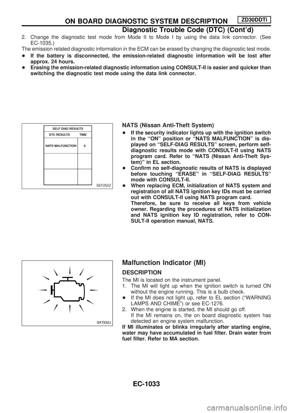
NATS (Nissan Anti-Theft System)
+If the security indicator lights up with the ignition switch
in the ªONº position or ªNATS MALFUNCTIONº is dis-
played on ªSELF-DIAG RESULTSº screen, perform self-
diagnostic results mode with CONSULT-II using NATS
program card. Refer to ªNATS (Nissan Anti-Theft Sys-
tem)º in EL section.
+Confirm no self-diagnostic results of NATS is displayed
before touching ªERASEº in ªSELF-DIAG RESULTSº
mode with CONSULT-II.
+When replacing ECM, initialization of NATS system and
registration of all NATS ignition key IDs must be carried
out with CONSULT-II using NATS program card.
Therefore, be sure to receive all keys from vehicle
owner. Regarding the procedures of NATS initialization
and NATS ignition key ID registration, refer to CON-
SULT-II operation manual, NATS.
Malfunction Indicator (MI)
DESCRIPTION
The MI is located on the instrument panel.
1. The MI will light up when the ignition switch is turned ON
without the engine running. This is a bulb check.
+If the MI does not light up, refer to EL section (ªWARNING
LAMPS AND CHIMEº) or see EC-1276.
2. When the engine is started, the MI should go off.
If the MI remains on, the on board diagnostic system has
detected an engine system malfunction.
If MI illuminates or blinks irregularly after starting engine,
water may have accumulated in fuel filter. Drain water from
fuel filter. Refer to MA section.
SEF252Z
SAT652J
ON BOARD DIAGNOSTIC SYSTEM DESCRIPTIONZD30DDTi
Diagnostic Trouble Code (DTC) (Cont'd)
EC-1033
Page 582 of 1033
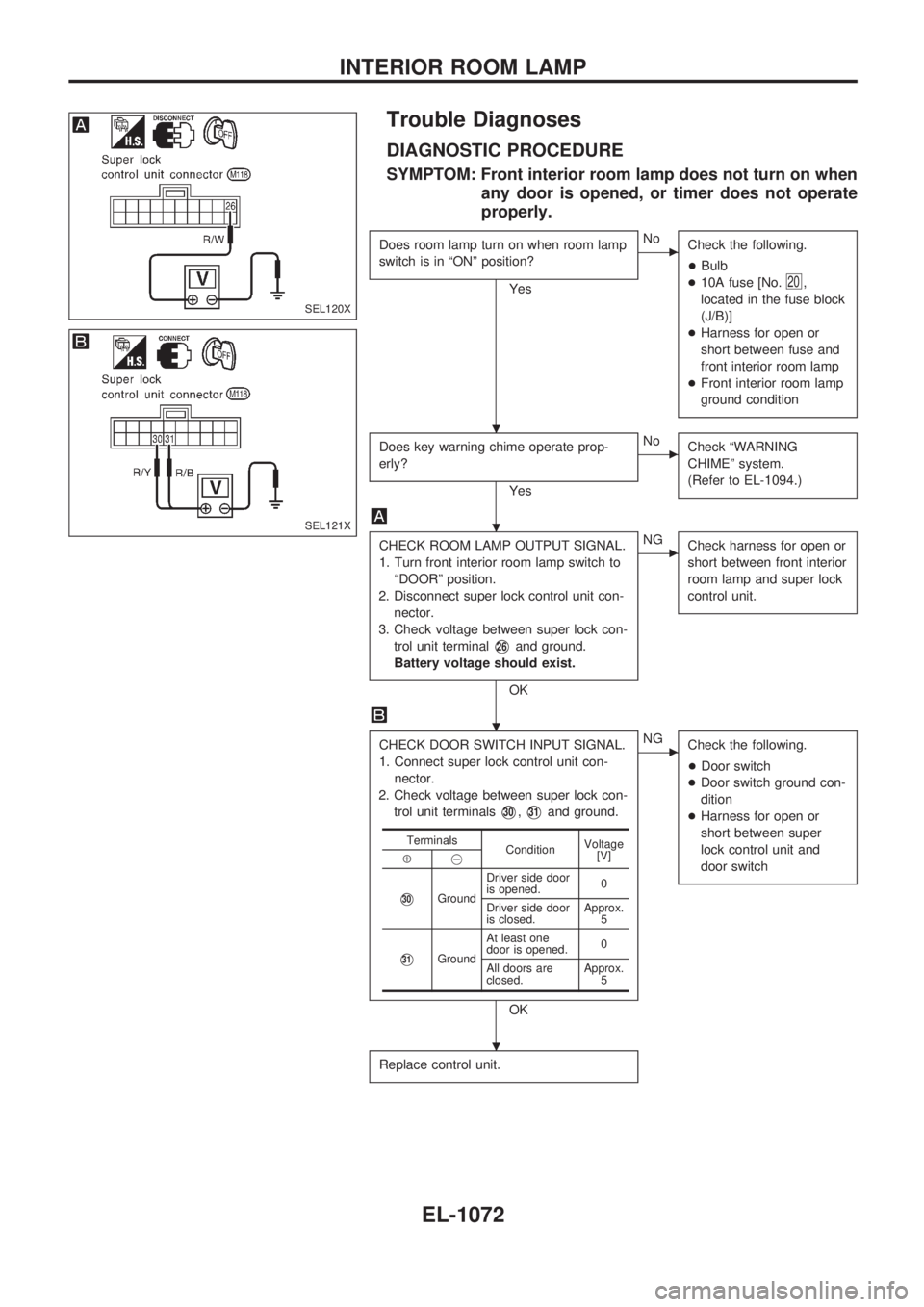
Trouble Diagnoses
DIAGNOSTIC PROCEDURE
SYMPTOM: Front interior room lamp does not turn on when
any door is opened, or timer does not operate
properly.
Does room lamp turn on when room lamp
switch is in ªONº position?
Yes
cNo
Check the following.
+Bulb
+10A fuse [No.
20,
located in the fuse block
(J/B)]
+Harness for open or
short between fuse and
front interior room lamp
+Front interior room lamp
ground condition
Does key warning chime operate prop-
erly?
Yes
cNo
Check ªWARNING
CHIMEº system.
(Refer to EL-1094.)
CHECK ROOM LAMP OUTPUT SIGNAL.
1. Turn front interior room lamp switch to
ªDOORº position.
2. Disconnect super lock control unit con-
nector.
3. Check voltage between super lock con-
trol unit terminal
V26and ground.
Battery voltage should exist.
OK
cNG
Check harness for open or
short between front interior
room lamp and super lock
control unit.
CHECK DOOR SWITCH INPUT SIGNAL.
1. Connect super lock control unit con-
nector.
2. Check voltage between super lock con-
trol unit terminals
V30,V31and ground.
OK
cNG
Check the following.
+Door switch
+Door switch ground con-
dition
+Harness for open or
short between super
lock control unit and
door switch
Replace control unit.
Terminals
ConditionVoltage
[V]
Å@
V30GroundDriver side door
is opened.0
Driver side door
is closed.Approx.
5
V31GroundAt least one
door is opened.0
All doors are
closed.Approx.
5
SEL120X
SEL121X
.
.
.
.
INTERIOR ROOM LAMP
EL-1072
Page 636 of 1033

Key reminder system
+If the ignition key is in the ignition key cylinder and the driver door is open, setting lock knob on driver door,
key or multi-remote controller to ªLOCKº locks the door once but then immediately unlocks all doors. (Sig-
nal from unlock sensor driver side)
System initialization
+System initialization is required when battery cables are reconnected. Conduct one of the followings to
release super lock once;
Ð insert the key into ignition key cylinder and turn it to ON.
Ð LOCK/UNLOCK operation using door key cylinder or multi-remote controller.
POWER DOOR LOCK Ð Super Lock Ð
System Description (Cont'd)
EL-1126
Page 658 of 1033
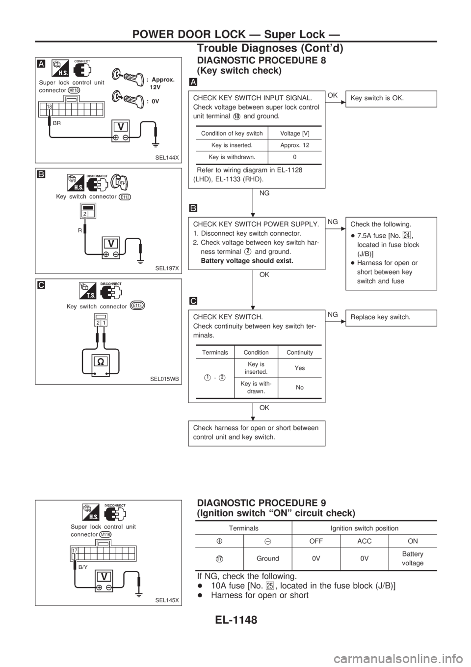
DIAGNOSTIC PROCEDURE 8
(Key switch check)
CHECK KEY SWITCH INPUT SIGNAL.
Check voltage between super lock control
unit terminal
V18and ground.
Refer to wiring diagram in EL-1128
(LHD), EL-1133 (RHD).
NG
cOK
Key switch is OK.
CHECK KEY SWITCH POWER SUPPLY.
1. Disconnect key switch connector.
2. Check voltage between key switch har-
ness terminal
V2and ground.
Battery voltage should exist.
OK
cNG
Check the following.
+7.5A fuse [No.
24,
located in fuse block
(J/B)]
+Harness for open or
short between key
switch and fuse
CHECK KEY SWITCH.
Check continuity between key switch ter-
minals.
OK
cNG
Replace key switch.
Check harness for open or short between
control unit and key switch.
Condition of key switch Voltage [V]
Key is inserted. Approx. 12
Key is withdrawn. 0
Terminals Condition Continuity
V1-V2
Key is
inserted.Yes
Key is with-
drawn.No
DIAGNOSTIC PROCEDURE 9
(Ignition switch ªONº circuit check)
Terminals Ignition switch position
Å@OFF ACC ON
V17Ground 0V 0VBattery
voltage
If NG, check the following.
+10A fuse [No.
25, located in the fuse block (J/B)]
+Harness for open or short
SEL144X
SEL197X
SEL015WB
SEL145X
.
.
.
POWER DOOR LOCK Ð Super Lock Ð
Trouble Diagnoses (Cont'd)
EL-1148
Page 659 of 1033
System Description
FUNCTION
Multi-remote control system has the following function.
+Door lock
+Door unlock
+Hazard reminder
LOCK OPERATION
When the LOCK signal is input to multi-remote control unit (the antenna of the system is combined with
multi-remote control unit), ground is supplied
+through multi-remote control unit terminal
V5
+to super lock control unit terminalV32.
Then super lock control unit locks all doors and set super lock. (Super lock will not be set while key is inserted
in the ignition key cylinder.)
UNLOCK OPERATION
When the UNLOCK signal is input to multi-remote control unit (the antenna of the system is combined with
multi-remote control unit) once, ground is supplied
+through multi-remote control unit terminal
V6
+to super lock control unit terminalV33.
Then super lock control unit unlocks driver's door and release super lock on all doors.
If the UNLOCK signal is sent to the multi-remote control unit again within 5 seconds, all other doors will be
unlocked.
HAZARD REMINDER
When the doors are locked or unlocked (signal from front door unlock sensor LH) by multi-remote controller,
power is supplied
+through multi-remote control unit terminals
V3andV8
+to the hazard warning lamps
Then hazard warning lamp flashes as follows.
+Lock operation: Flash once
+Unlock operation: Flash twice
MULTI-REMOTE CONTROLLER ID CODE ENTRY
A maximum of four remote controllers can be entered. Any attempt to enter a remote controller will erase
all ID codes previously entered. Therefore, be sure to receive all remote controllers from the vehicle owner
when any ID code entry is performed.
To enter ID code entry, the following signals must be input to the multi-remote control unit.
+Ignition switch ON signal
+Battery power supply
+Signal from remote controller
For detailed procedure, refer to ªID Code Entry Procedureº in EL-1156.
MULTI-REMOTE CONTROL SYSTEM
EL-1149
Page 664 of 1033
Trouble Diagnoses
SYMPTOM CHART
Symptom Possible cause Diagnoses/service order
No doors can be locked or un-
locked by remote control opera-
tion. (See NOTE.)1. Power door lock system
2. Remote controller battery
3. Door lock/unlock circuit
4. Ignition power supply circuit for
multi-remote control unit
5. Power supply circuit for multi-re-
mote control unit
6. Ground circuit for multi-remote
control unit
7. Remote controller1. Check power door lock operation.
2. Check remote controller battery. Refer to ªRemote
controller battery checkº in EL section of Service
Manual (SM7E-2Y61G1).
3. Check harness for open or short between multi-remote
control unit and super lock control unit.
4. Make sure battery voltage is present at terminal
V4of
multi-remote control unit while ignition switch is in IGN
position.
5. Make sure battery voltage is present at terminal
V2of multi-remote control unit.
6. Check continuity between terminal
V1of multi-remote
control unit and ground.
7. Replace remote controller. Refer to EL-1156.
Hazard reminder does not operate
properly.1. Hazard reminder output to haz-
ard warning lamps
2. Hazard reminder circuit
3. Driver's door unlock sensor1. Check hazard reminder output to hazard warning
lamps at terminals
V3andV8of multi-remote control
unit.
2. Check the harness for open or short between hazard
warning lamps and multi-remote control unit.
3. Check driver's door unlock sensor signal at terminal
V7of multi-remote control unit.
The new ID of remote controller
cannot be entered.1. Remote controller battery
2. Ignition power supply circuit
for multi-remote control unit
3. Driver's door unlock sensor
4. Remote controller1. Check remote controller battery. Refer to ªRemote
controller battery checkº in EL section of Service
Manual (SM7E-2Y61G1).
2. Make sure battery voltage is present at terminal
V4of
multi-remote control unit while ignition switch is in IGN
position.
3. Check driver's door unlock sensor signal at terminal
V7of multi-remote control unit.
4. Replace remote controller. Refer to EL-1156.
Refer to ªMULTI-REMOTE CONTROL UNIT INSPECTION TABLEº on next page to check the control unit
signals.
NOTE:
+The lock operation of multi-remote control system does not activate with the ignition key ON position.
MULTI-REMOTE CONTROL SYSTEM
EL-1154