2000 NISSAN PATROL warning
[x] Cancel search: warningPage 6 of 1033
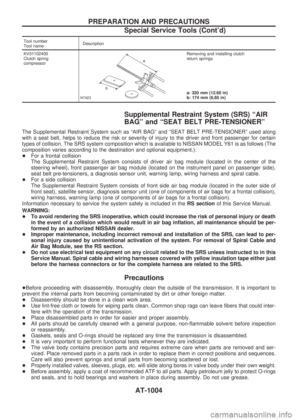
Tool number
Tool nameDescription
KV31102400
Clutch spring
compressor
NT423
Removing and installing clutch
return springs
a: 320 mm (12.60 in)
b: 174 mm (6.85 in)
Supplemental Restraint System (SRS) ªAIR
BAGº and ªSEAT BELT PRE-TENSIONERº
The Supplemental Restraint System such as ªAIR BAGº and ªSEAT BELT PRE-TENSIONERº used along
with a seat belt, helps to reduce the risk or severity of injury to the driver and front passenger for certain
types of collision. The SRS system composition which is available to NISSAN MODEL Y61 is as follows (The
composition varies according to the destination and optional equipment.):
+For a frontal collision
The Supplemental Restraint System consists of driver air bag module (located in the center of the
steering wheel), front passenger air bag module (located on the instrument panel on passenger side),
seat belt pre-tensioners, a diagnosis sensor unit, warning lamp, wiring harness and spiral cable.
+For a side collision
The Supplemental Restraint System consists of front side air bag module (located in the outer side of
front seat), satellite sensor, diagnosis sensor unit (one of components of air bags for a frontal collision),
wiring harness, warning lamp (one of components of air bags for a frontal collision).
Information necessary to service the system safely is included in theRS sectionof this Service Manual.
WARNING:
+To avoid rendering the SRS inoperative, which could increase the risk of personal injury or death
in the event of a collision which would result in air bag inflation, all maintenance should be per-
formed by an authorized NISSAN dealer.
+Improper maintenance, including incorrect removal and installation of the SRS, can lead to per-
sonal injury caused by unintentional activation of the system. For removal of Spiral Cable and
Air Bag Module, see the RS section.
+Do not use electrical test equipment on any circuit related to the SRS unless instructed to in this
Service Manual. Spiral cable and wiring harnesses covered with yellow insulation tape either just
before the harness connectors or for the complete harness are related to the SRS.
Precautions
+Before proceeding with disassembly, thoroughly clean the outside of the transmission. It is important to
prevent the internal parts from becoming contaminated by dirt or other foreign matter.
+Disassembly should be done in a clean work area.
+Use lint-free cloth or towels for wiping parts clean. Common shop rags can leave fibers that could inter-
fere with the operation of the transmission.
+Place disassembled parts in order for easier and proper assembly.
+All parts should be carefully cleaned with a general purpose, non-flammable solvent before inspection
or reassembly.
+Gaskets, seals and O-rings should be replaced any time the transmission is disassembled.
+It is very important to perform functional tests whenever they are indicated.
+The valve body contains precision parts and requires extreme care when parts are removed and ser-
viced. Place removed parts in a parts rack in order to replace them in correct positions and sequences.
Care will also prevent springs and small parts from becoming scattered or lost.
+Properly installed valves, sleeves, plugs, etc. will slide along bores in valve body under their own weight.
+Before assembly, apply a coat of recommended ATF to all parts. Apply petroleum jelly to protect O-rings
and seals, and to hold bearings and washers in place during assembly. Do not use grease.
PREPARATION AND PRECAUTIONS
Special Service Tools (Cont'd)
AT-1004
Page 98 of 1033
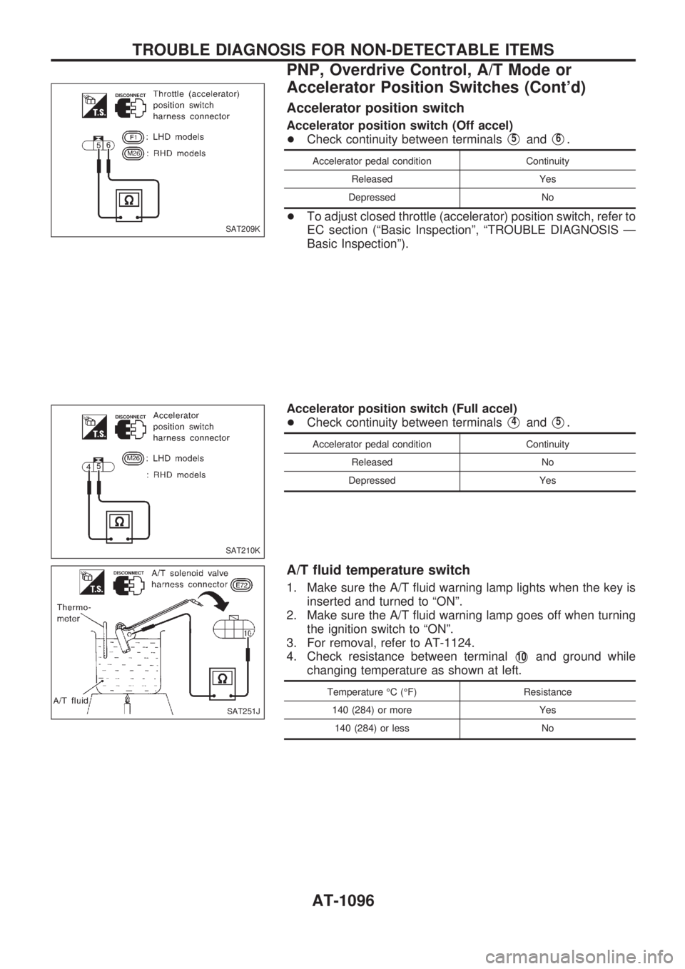
Accelerator position switch
Accelerator position switch (Off accel)
+Check continuity between terminals
V5andV6.
Accelerator pedal condition Continuity
Released Yes
Depressed No
+To adjust closed throttle (accelerator) position switch, refer to
EC section (ªBasic Inspectionº, ªTROUBLE DIAGNOSIS Ð
Basic Inspectionº).
Accelerator position switch (Full accel)
+Check continuity between terminals
V4andV5.
Accelerator pedal condition Continuity
Released No
Depressed Yes
A/T fluid temperature switch
1. Make sure the A/T fluid warning lamp lights when the key is
inserted and turned to ªONº.
2. Make sure the A/T fluid warning lamp goes off when turning
the ignition switch to ªONº.
3. For removal, refer to AT-1124.
4. Check resistance between terminal
V10and ground while
changing temperature as shown at left.
Temperature ÉC (ÉF) Resistance
140 (284) or more Yes
140 (284) or less No
SAT209K
SAT210K
SAT251J
TROUBLE DIAGNOSIS FOR NON-DETECTABLE ITEMS
PNP, Overdrive Control, A/T Mode or
Accelerator Position Switches (Cont'd)
AT-1096
Page 99 of 1033
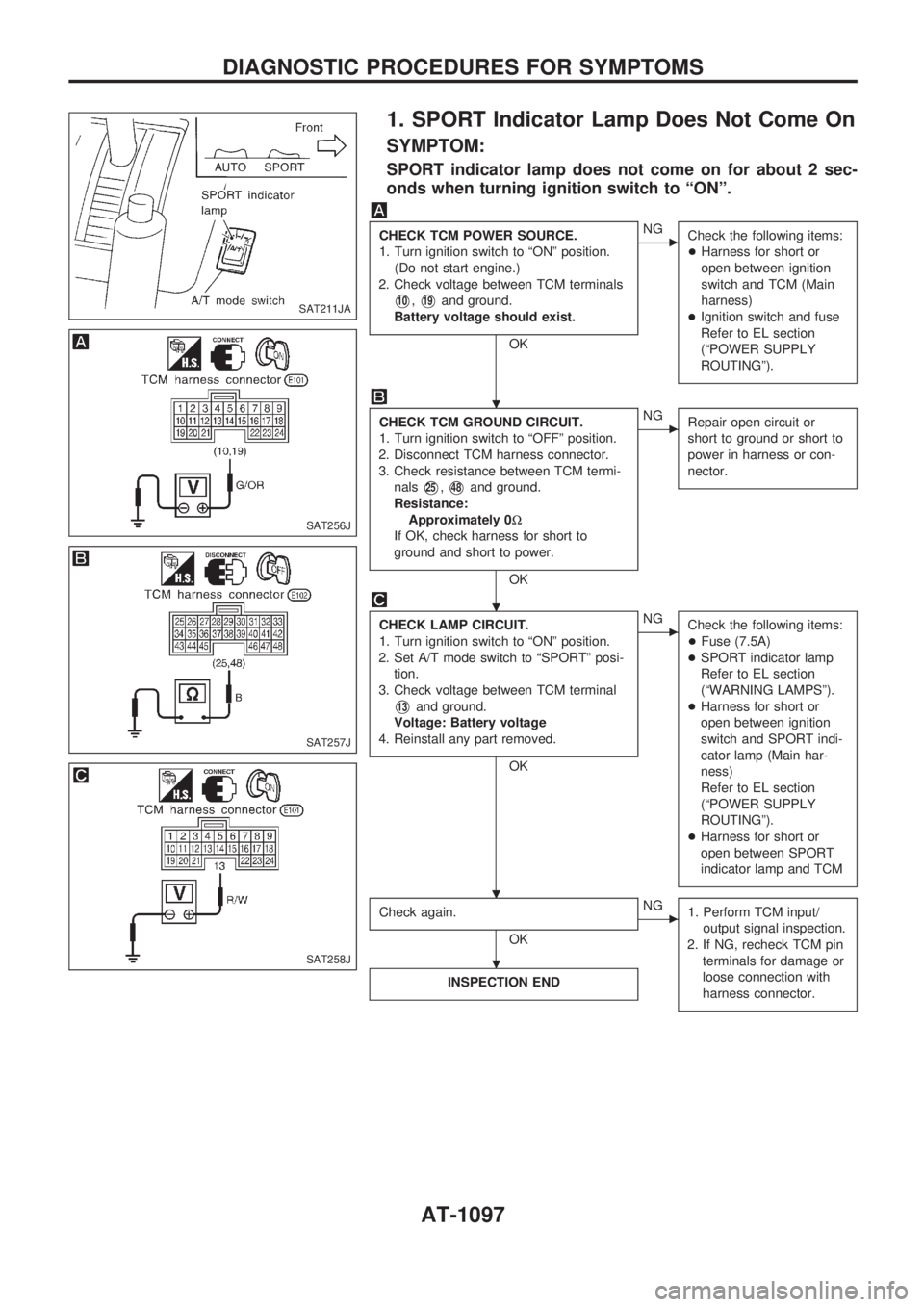
1. SPORT Indicator Lamp Does Not Come On
SYMPTOM:
SPORT indicator lamp does not come on for about 2 sec-
onds when turning ignition switch to ªONº.
CHECK TCM POWER SOURCE.
1. Turn ignition switch to ªONº position.
(Do not start engine.)
2. Check voltage between TCM terminals
V10,V19and ground.
Battery voltage should exist.
OK
cNG
Check the following items:
+Harness for short or
open between ignition
switch and TCM (Main
harness)
+Ignition switch and fuse
Refer to EL section
(ªPOWER SUPPLY
ROUTINGº).
CHECK TCM GROUND CIRCUIT.
1. Turn ignition switch to ªOFFº position.
2. Disconnect TCM harness connector.
3. Check resistance between TCM termi-
nals
V25,V48and ground.
Resistance:
Approximately 0W
If OK, check harness for short to
ground and short to power.
OK
cNG
Repair open circuit or
short to ground or short to
power in harness or con-
nector.
CHECK LAMP CIRCUIT.
1. Turn ignition switch to ªONº position.
2. Set A/T mode switch to ªSPORTº posi-
tion.
3. Check voltage between TCM terminal
V13and ground.
Voltage: Battery voltage
4. Reinstall any part removed.
OK
cNG
Check the following items:
+Fuse (7.5A)
+SPORT indicator lamp
Refer to EL section
(ªWARNING LAMPSº).
+Harness for short or
open between ignition
switch and SPORT indi-
cator lamp (Main har-
ness)
Refer to EL section
(ªPOWER SUPPLY
ROUTINGº).
+Harness for short or
open between SPORT
indicator lamp and TCM
Check again.
OK
cNG
1. Perform TCM input/
output signal inspection.
2. If NG, recheck TCM pin
terminals for damage or
loose connection with
harness connector.
INSPECTION END
SAT211JA
SAT256J
SAT257J
SAT258J
.
.
. .
.
DIAGNOSTIC PROCEDURES FOR SYMPTOMS
AT-1097
Page 220 of 1033
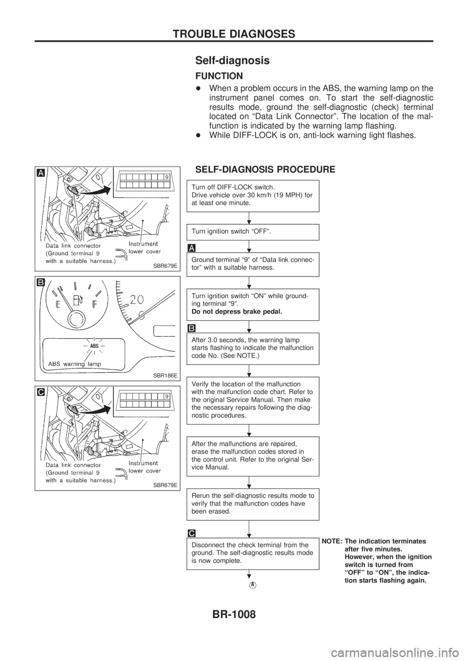
Self-diagnosis
FUNCTION
+When a problem occurs in the ABS, the warning lamp on the
instrument panel comes on. To start the self-diagnostic
results mode, ground the self-diagnostic (check) terminal
located on ªData Link Connectorº. The location of the mal-
function is indicated by the warning lamp flashing.
+While DIFF-LOCK is on, anti-lock warning light flashes.
SELF-DIAGNOSIS PROCEDURE
Turn off DIFF-LOCK switch.
Drive vehicle over 30 km/h (19 MPH) for
at least one minute.
Turn ignition switch ªOFFº.
Ground terminal ª9º of ªData link connec-
torº with a suitable harness.
Turn ignition switch ªONº while ground-
ing terminal ª9º.
Do not depress brake pedal.
After 3.0 seconds, the warning lamp
starts flashing to indicate the malfunction
code No. (See NOTE.)
Verify the location of the malfunction
with the malfunction code chart. Refer to
the original Service Manual. Then make
the necessary repairs following the diag-
nostic procedures.
After the malfunctions are repaired,
erase the malfunction codes stored in
the control unit. Refer to the original Ser-
vice Manual.
Rerun the self-diagnostic results mode to
verify that the malfunction codes have
been erased.
Disconnect the check terminal from the
ground. The self-diagnostic results mode
is now complete.NOTE: The indication terminates
after five minutes.
However, when the ignition
switch is turned from
ªOFFº to ªONº, the indica-
tion starts flashing again.
VA
SBR679E
SBR186E
SBR679E
.
.
.
.
.
.
.
.
.
TROUBLE DIAGNOSES
BR-1008
Page 221 of 1033
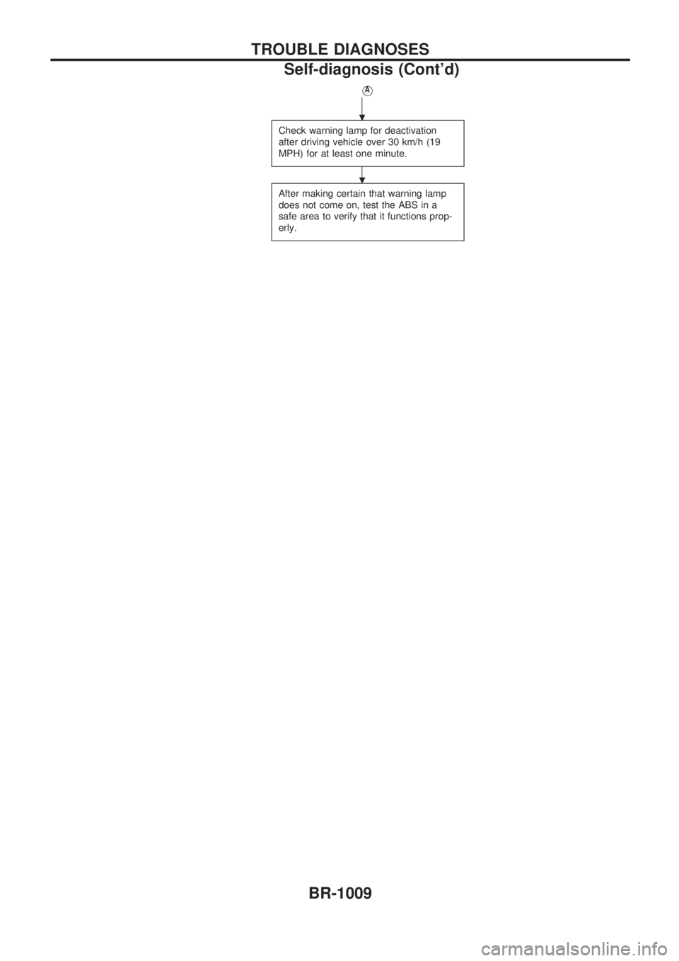
VA
Check warning lamp for deactivation
after driving vehicle over 30 km/h (19
MPH) for at least one minute.
After making certain that warning lamp
does not come on, test the ABS in a
safe area to verify that it functions prop-
erly.
.
.
TROUBLE DIAGNOSES
Self-diagnosis (Cont'd)
BR-1009
Page 224 of 1033
Supplemental Restraint System (SRS) ªAIR
BAGº and ªSEAT BELT PRE-TENSIONERº
The Supplemental Restraint System such as ªAIR BAGº and ªSEAT BELT PRE-TENSIONERº used along
with a seat belt, helps to reduce the risk or severity of injury to the driver and front passenger for certain
types of collision. The SRS system composition which is available to NISSAN MODEL Y61 is as follows (The
composition varies according to the destination and optional equipment.):
+For a frontal collision
The Supplemental Restraint System consists of driver air bag module (located in the center of the
steering wheel), front passenger air bag module (located on the instrument panel on passenger side),
seat belt pre-tensioners, a diagnosis sensor unit, warning lamp, wiring harness and spiral cable.
+ For a side collision
The Supplemental Restraint System consists of front side air bag module (located in the outer side of
front seat), satellite sensor, diagnosis sensor unit (one of components of air bags for a frontal collision),
wiring harness, warning lamp (one of components of air bags for a frontal collision).
Information necessary to service the system safely is included in the RS sectionof this Service Manual.
WARNING:
+ To avoid rendering the SRS inoperative, which could increase the risk of personal injury or death
in the event of a collision which would result in air bag inflation, all maintenance should be per-
formed by an authorized NISSAN dealer.
+ Improper maintenance, including incorrect removal and installation of the SRS, can lead to per-
sonal injury caused by intentional activation of the system. For removal of Spiral Cable and Air
Bag Module, see the RS section.
+ Do not use electrical test equipment on any circuit related to the SRS unless instructed to in this
Service Manual. Spiral cable and wiring harnesses covered with yellow insulation tape either just
before the harness connectors or for the complete harness are related to the SRS.
PRECAUTIONS
BT-1002
Page 238 of 1033
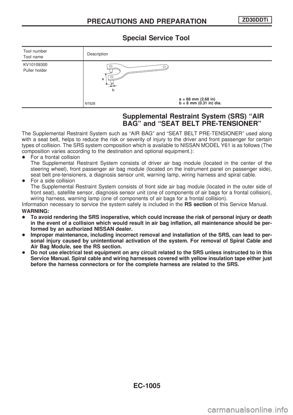
Special Service Tool
Tool number
Tool nameDescription
KV10109300
Puller holder
NT628a = 68 mm (2.68 in)
b = 8 mm (0.31 in) dia.
Supplemental Restraint System (SRS) ªAIR
BAGº and ªSEAT BELT PRE-TENSIONERº
The Supplemental Restraint System such as ªAIR BAGº and ªSEAT BELT PRE-TENSIONERº used along
with a seat belt, helps to reduce the risk or severity of injury to the driver and front passenger for certain
types of collision. The SRS system composition which is available to NISSAN MODEL Y61 is as follows (The
composition varies according to the destination and optional equipment.):
+For a frontal collision
The Supplemental Restraint System consists of driver air bag module (located in the center of the
steering wheel), front passenger air bag module (located on the instrument panel on passenger side),
seat belt pre-tensioners, a diagnosis sensor unit, warning lamp, wiring harness and spiral cable.
+For a side collision
The Supplemental Restraint System consists of front side air bag module (located in the outer side of
front seat), satellite sensor, diagnosis sensor unit (one of components of air bags for a frontal collision),
wiring harness, warning lamp (one of components of air bags for a frontal collision).
Information necessary to service the system safely is included in theRS sectionof this Service Manual.
WARNING:
+To avoid rendering the SRS inoperative, which could increase the risk of personal injury or death
in the event of a collision which would result in air bag inflation, all maintenance should be per-
formed by an authorized NISSAN dealer.
+Improper maintenance, including incorrect removal and installation of the SRS, can lead to per-
sonal injury caused by unintentional activation of the system. For removal of Spiral Cable and
Air Bag Module, see the RS section.
+Do not use electrical test equipment on any circuit related to the SRS unless instructed to in this
Service Manual. Spiral cable and wiring harnesses covered with yellow insulation tape either just
before the harness connectors or for the complete harness are related to the SRS.
PRECAUTIONS AND PREPARATIONZD30DDTi
EC-1005
Page 257 of 1033
Installation
+Install the injection tubes, referring to the markings made
during removal.
+Install the injection tubes in the order of No. 3, No. 4, No. 1,
and No. 2.
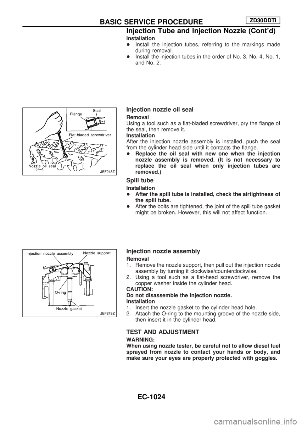
Injection nozzle oil seal
Removal
Using a tool such as a flat-bladed screwdriver, pry the flange of
the seal, then remove it.
Installation
After the injection nozzle assembly is installed, push the seal
from the cylinder head side until it contacts the flange.
+Replace the oil seal with new one when the injection
nozzle assembly is removed. (It is not necessary to
replace the oil seal when only injection tubes are
removed.)
Spill tube
Installation
+After the spill tube is installed, check the airtightness of
the spill tube.
+After the bolts are tightened, the joint of the spill tube gasket
might be broken. However, this will not affect function.
Injection nozzle assembly
Removal
1. Remove the nozzle support, then pull out the injection nozzle
assembly by turning it clockwise/counterclockwise.
2. Using a tool such as a flat-head screwdriver, remove the
copper washer inside the cylinder head.
CAUTION:
Do not disassemble the injection nozzle.
Installation
1. Insert the nozzle gasket to the cylinder head hole.
2. Attach the O-ring to the mounting groove of the nozzle side,
then insert it in the cylinder head.
TEST AND ADJUSTMENT
WARNING:
When using nozzle tester, be careful not to allow diesel fuel
sprayed from nozzle to contact your hands or body, and
make sure your eyes are properly protected with goggles.
JEF248Z
JEF249Z
BASIC SERVICE PROCEDUREZD30DDTi
Injection Tube and Injection Nozzle (Cont'd)
EC-1024