2000 NISSAN PATROL compression ratio
[x] Cancel search: compression ratioPage 288 of 1033
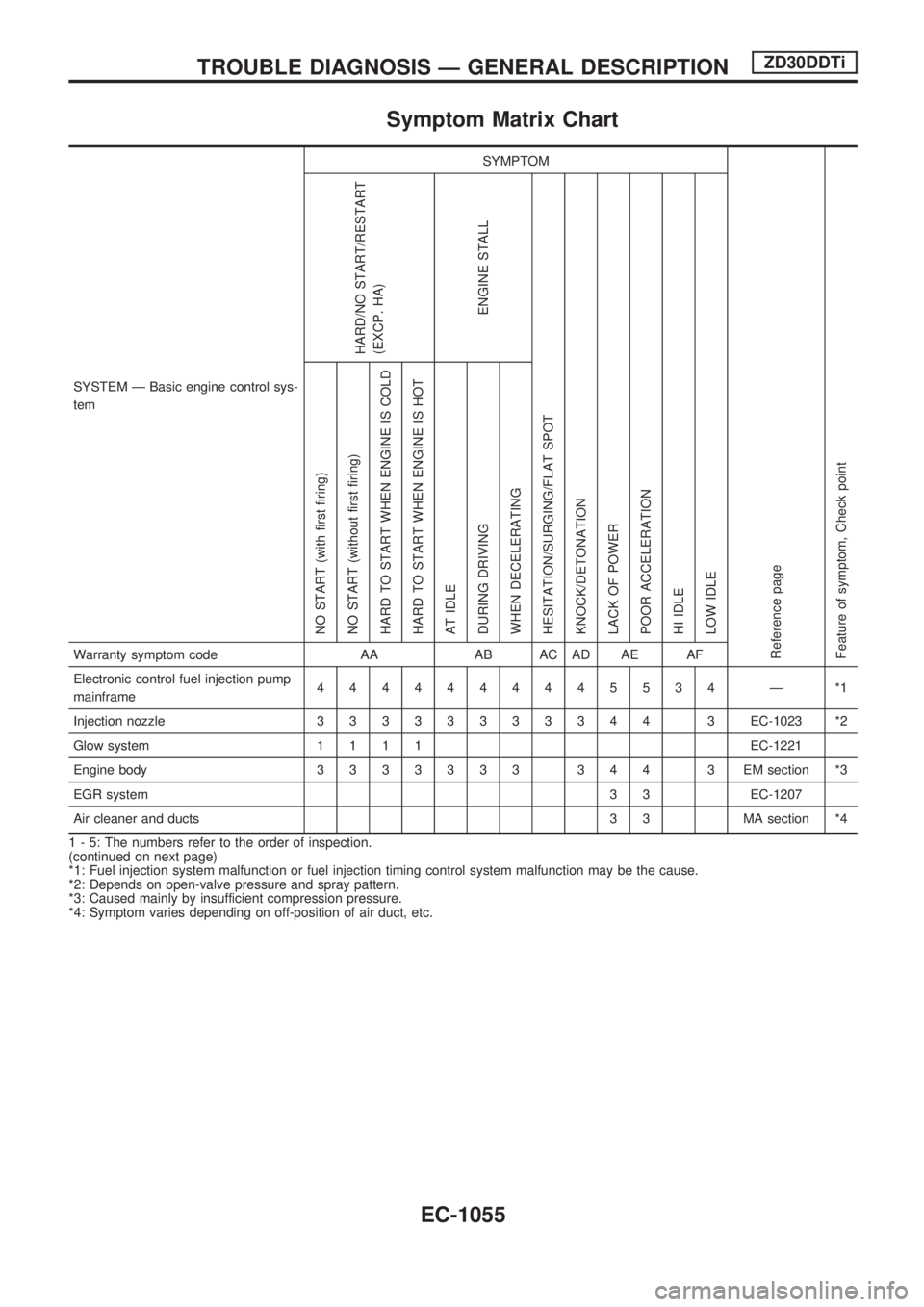
Symptom Matrix Chart
SYSTEM Ð Basic engine control sys-
temSYMPTOM
Reference page
Feature of symptom, Check pointHARD/NO START/RESTART
(EXCP. HA)
ENGINE STALL
HESITATION/SURGING/FLAT SPOT
KNOCK/DETONATION
LACK OF POWER
POOR ACCELERATION
HI IDLE
LOW IDLE NO START (with first firing)
NO START (without first firing)
HARD TO START WHEN ENGINE IS COLD
HARD TO START WHEN ENGINE IS HOT
AT IDLE
DURING DRIVING
WHEN DECELERATINGWarranty symptom code AA AB AC AD AE AF
Electronic control fuel injection pump
mainframe4444444445534 Ð *1
Injection nozzle33333333344 3EC-1023 *2
Glow system1111EC-1221
Engine body3333333 344 3 EMsection *3
EGR system3 3 EC-1207
Air cleaner and ducts 3 3 MA section *4
1 - 5: The numbers refer to the order of inspection.
(continued on next page)
*1: Fuel injection system malfunction or fuel injection timing control system malfunction may be the cause.
*2: Depends on open-valve pressure and spray pattern.
*3: Caused mainly by insufficient compression pressure.
*4: Symptom varies depending on off-position of air duct, etc.
TROUBLE DIAGNOSIS Ð GENERAL DESCRIPTIONZD30DDTi
EC-1055
Page 289 of 1033
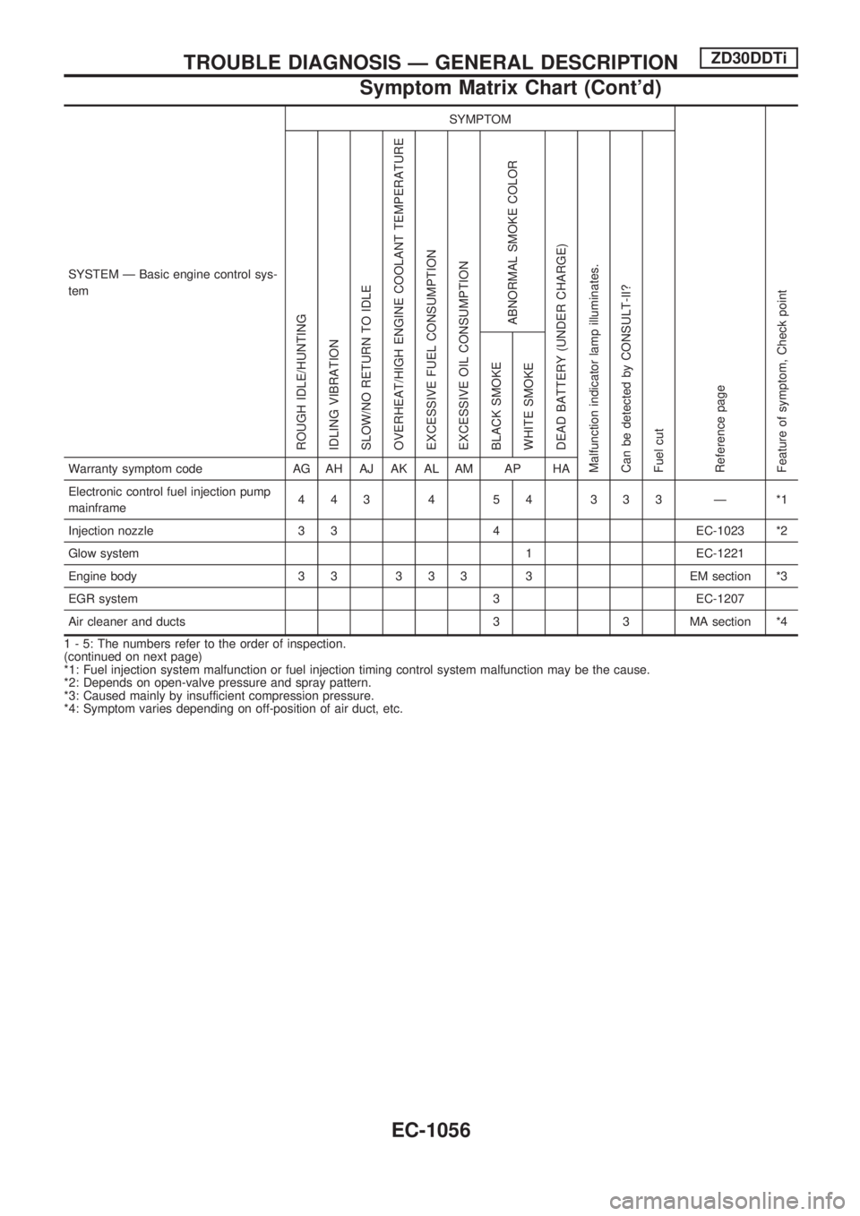
SYSTEM Ð Basic engine control sys-
temSYMPTOM
Reference page
Feature of symptom, Check pointROUGH IDLE/HUNTING
IDLING VIBRATION
SLOW/NO RETURN TO IDLE
OVERHEAT/HIGH ENGINE COOLANT TEMPERATURE
EXCESSIVE FUEL CONSUMPTION
EXCESSIVE OIL CONSUMPTION
ABNORMAL SMOKE COLOR
DEAD BATTERY (UNDER CHARGE)
Malfunction indicator lamp illuminates.
Can be detected by CONSULT-II?
Fuel cutBLACK SMOKE
WHITE SMOKEWarranty symptom code AG AH AJ AK AL AM AP HA
Electronic control fuel injection pump
mainframe443 4 54 333 Ð *1
Injection nozzle 3 3 4 EC-1023 *2
Glow system 1 EC-1221
Engine body 3 3 3 3 3 3 EM section *3
EGR system 3 EC-1207
Air cleaner and ducts 3 3 MA section *4
1 - 5: The numbers refer to the order of inspection.
(continued on next page)
*1: Fuel injection system malfunction or fuel injection timing control system malfunction may be the cause.
*2: Depends on open-valve pressure and spray pattern.
*3: Caused mainly by insufficient compression pressure.
*4: Symptom varies depending on off-position of air duct, etc.
TROUBLE DIAGNOSIS Ð GENERAL DESCRIPTIONZD30DDTi
Symptom Matrix Chart (Cont'd)
EC-1056
Page 739 of 1033
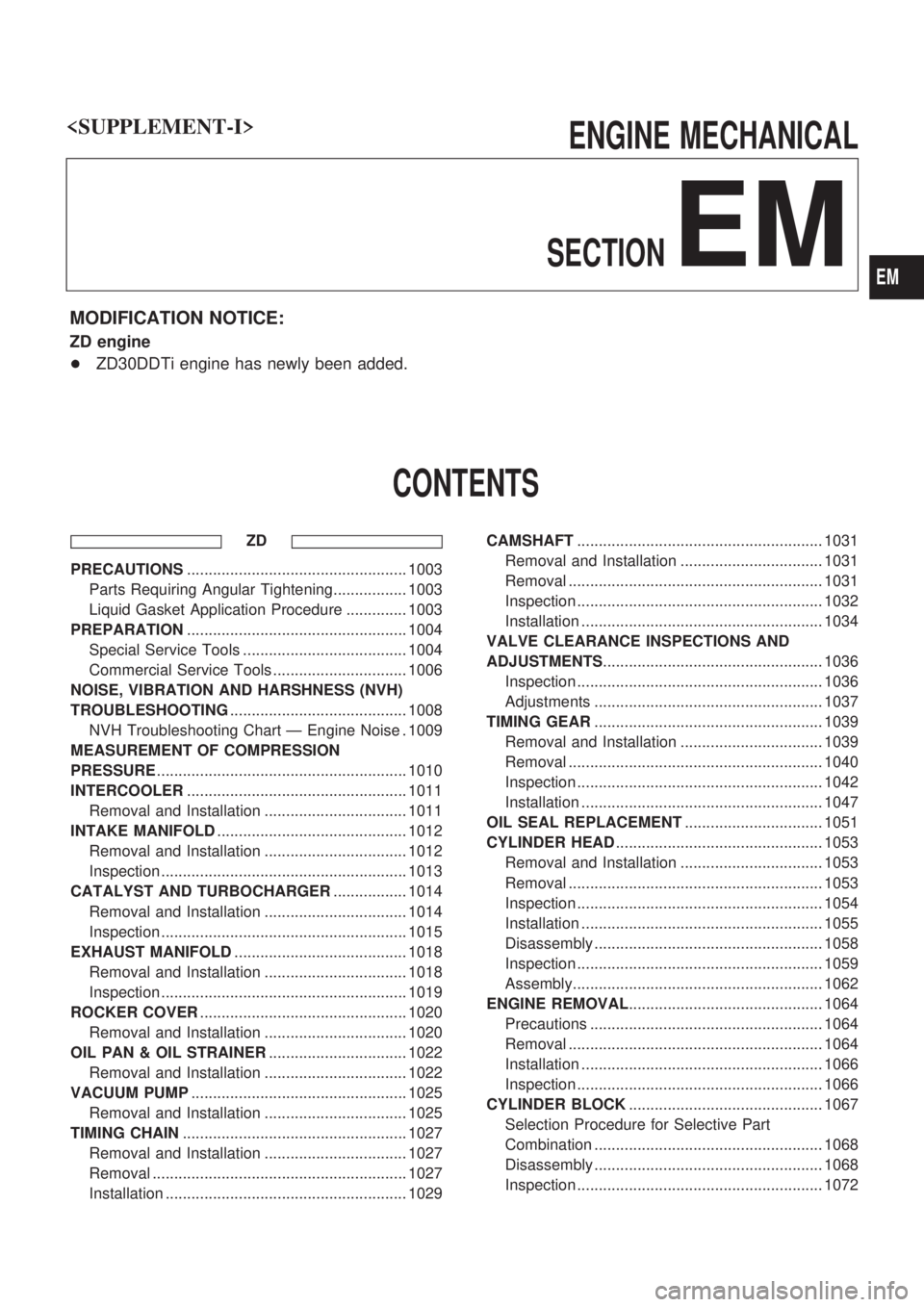
ENGINE MECHANICAL
SECTION
EM
MODIFICATION NOTICE:
ZD engine
+ZD30DDTi engine has newly been added.
CONTENTS
ZD
PRECAUTIONS................................................... 1003
Parts Requiring Angular Tightening................. 1003
Liquid Gasket Application Procedure .............. 1003
PREPARATION................................................... 1004
Special Service Tools ...................................... 1004
Commercial Service Tools ............................... 1006
NOISE, VIBRATION AND HARSHNESS (NVH)
TROUBLESHOOTING......................................... 1008
NVH Troubleshooting Chart Ð Engine Noise . 1009
MEASUREMENT OF COMPRESSION
PRESSURE.......................................................... 1010
INTERCOOLER................................................... 1011
Removal and Installation ................................. 1011
INTAKE MANIFOLD............................................ 1012
Removal and Installation ................................. 1012
Inspection ......................................................... 1013
CATALYST AND TURBOCHARGER................. 1014
Removal and Installation ................................. 1014
Inspection ......................................................... 1015
EXHAUST MANIFOLD........................................ 1018
Removal and Installation ................................. 1018
Inspection ......................................................... 1019
ROCKER COVER................................................ 1020
Removal and Installation ................................. 1020
OIL PAN & OIL STRAINER................................ 1022
Removal and Installation ................................. 1022
VACUUM PUMP.................................................. 1025
Removal and Installation ................................. 1025
TIMING CHAIN.................................................... 1027
Removal and Installation ................................. 1027
Removal ........................................................... 1027
Installation ........................................................ 1029CAMSHAFT......................................................... 1031
Removal and Installation ................................. 1031
Removal ........................................................... 1031
Inspection ......................................................... 1032
Installation ........................................................ 1034
VALVE CLEARANCE INSPECTIONS AND
ADJUSTMENTS................................................... 1036
Inspection ......................................................... 1036
Adjustments ..................................................... 1037
TIMING GEAR..................................................... 1039
Removal and Installation ................................. 1039
Removal ........................................................... 1040
Inspection ......................................................... 1042
Installation ........................................................ 1047
OIL SEAL REPLACEMENT................................ 1051
CYLINDER HEAD................................................ 1053
Removal and Installation ................................. 1053
Removal ........................................................... 1053
Inspection ......................................................... 1054
Installation ........................................................ 1055
Disassembly ..................................................... 1058
Inspection ......................................................... 1059
Assembly.......................................................... 1062
ENGINE REMOVAL............................................. 1064
Precautions ...................................................... 1064
Removal ........................................................... 1064
Installation ........................................................ 1066
Inspection ......................................................... 1066
CYLINDER BLOCK............................................. 1067
Selection Procedure for Selective Part
Combination ..................................................... 1068
Disassembly ..................................................... 1068
Inspection ......................................................... 1072
EM
Page 743 of 1033
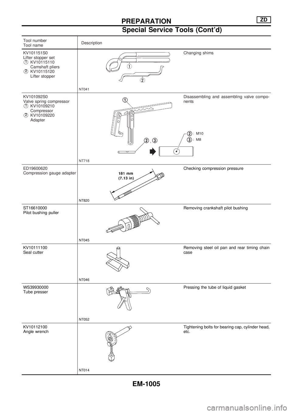
Tool number
Tool nameDescription
KV101151S0
Lifter stopper set
V1KV10115110
Camshaft pliers
V2KV10115120
Lifter stopper
NT041
Changing shims
KV101092S0
Valve spring compressor
V1KV10109210
Compressor
V2KV10109220
Adapter
NT718
Disassembling and assembling valve compo-
nents
ED19600620
Compression gauge adapter
NT820
Checking compression pressure
ST16610000
Pilot bushing puller
NT045
Removing crankshaft pilot bushing
KV10111100
Seal cutter
NT046
Removing steel oil pan and rear timing chain
case
WS39930000
Tube presser
NT052
Pressing the tube of liquid gasket
KV10112100
Angle wrench
NT014
Tightening bolts for bearing cap, cylinder head,
etc.
PREPARATIONZD
Special Service Tools (Cont'd)
EM-1005
Page 748 of 1033
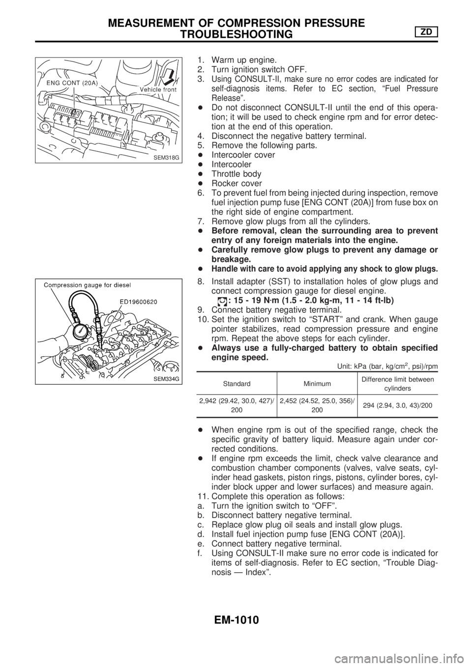
1. Warm up engine.
2. Turn ignition switch OFF.
3.
Using CONSULT-II, make sure no error codes are indicated for
self-diagnosis items. Refer to EC section, ªFuel Pressure
Releaseº.
+Do not disconnect CONSULT-II until the end of this opera-
tion; it will be used to check engine rpm and for error detec-
tion at the end of this operation.
4. Disconnect the negative battery terminal.
5. Remove the following parts.
+Intercooler cover
+Intercooler
+Throttle body
+Rocker cover
6. To prevent fuel from being injected during inspection, remove
fuel injection pump fuse [ENG CONT (20A)] from fuse box on
the right side of engine compartment.
7. Remove glow plugs from all the cylinders.
+Before removal, clean the surrounding area to prevent
entry of any foreign materials into the engine.
+Carefully remove glow plugs to prevent any damage or
breakage.
+
Handle with care to avoid applying any shock to glow plugs.
8. Install adapter (SST) to installation holes of glow plugs and
connect compression gauge for diesel engine.
:15-19Nzm (1.5 - 2.0 kg-m, 11 - 14 ft-lb)
9. Connect battery negative terminal.
10. Set the ignition switch to ªSTARTº and crank. When gauge
pointer stabilizes, read compression pressure and engine
rpm. Repeat the above steps for each cylinder.
+Always use a fully-charged battery to obtain specified
engine speed.
Unit: kPa (bar, kg/cm2, psi)/rpm
Standard MinimumDifference limit between
cylinders
2,942 (29.42, 30.0, 427)/
2002,452 (24.52, 25.0, 356)/
200294 (2.94, 3.0, 43)/200
+When engine rpm is out of the specified range, check the
specific gravity of battery liquid. Measure again under cor-
rected conditions.
+If engine rpm exceeds the limit, check valve clearance and
combustion chamber components (valves, valve seats, cyl-
inder head gaskets, piston rings, pistons, cylinder bores, cyl-
inder block upper and lower surfaces) and measure again.
11. Complete this operation as follows:
a. Turn the ignition switch to ªOFFº.
b. Disconnect battery negative terminal.
c. Replace glow plug oil seals and install glow plugs.
d. Install fuel injection pump fuse [ENG CONT (20A)].
e. Connect battery negative terminal.
f. Using CONSULT-II make sure no error code is indicated for
items of self-diagnosis. Refer to EC section, ªTrouble Diag-
nosis Ð Indexº.
SEM318G
SEM334G
MEASUREMENT OF COMPRESSION PRESSURE
TROUBLESHOOTINGZD
EM-1010
Page 823 of 1033
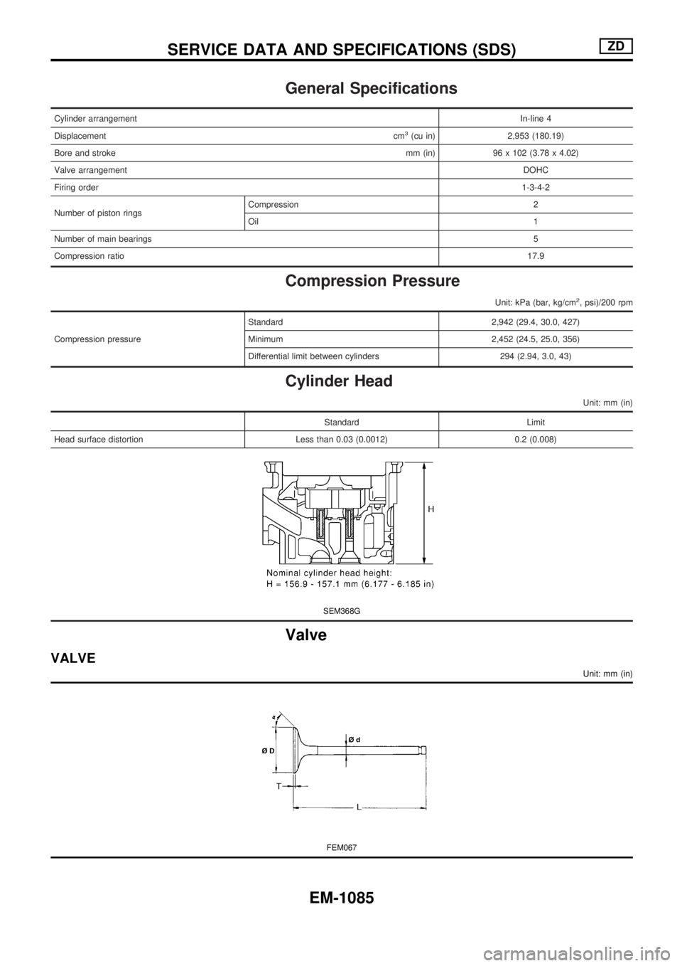
General Specifications
Cylinder arrangementIn-line 4
Displacementcm
3(cu in) 2,953 (180.19)
Bore and strokemm (in) 96 x 102 (3.78 x 4.02)
Valve arrangementDOHC
Firing order1-3-4-2
Number of piston ringsCompression 2
Oil1
Number of main bearings5
Compression ratio17.9
Compression Pressure
Unit: kPa (bar, kg/cm2, psi)/200 rpm
Compression pressureStandard 2,942 (29.4, 30.0, 427)
Minimum 2,452 (24.5, 25.0, 356)
Differential limit between cylinders 294 (2.94, 3.0, 43)
Cylinder Head
Unit: mm (in)
Standard Limit
Head surface distortion Less than 0.03 (0.0012) 0.2 (0.008)
SEM368G
Valve
VALVE
Unit: mm (in)
FEM067
SERVICE DATA AND SPECIFICATIONS (SDS)ZD
EM-1085
Page 880 of 1033
A
A/T - Wiring diagram ............................. AT-1009
A/T control ............................................. EC-1148
A/T fluid temperature sensor ................. AT-1081
A/T mode switch .................................... AT-1095
A/T self-diagnoses ................................. AT-1028
A/T shift lock system - Wiring
diagram .............................................. AT-1117
A/T shift lock system ............................. AT-1116
A/T trouble diagnoses ........................... AT-1036
APS - Wiring diagram ........................... EC-1125
ASCD (automatic speed control
device) ............................................... EL-1110
ASCD - Wiring diagram ......................... EL-1111
AT/C - Wiring diagram .......................... EC-1150
Accelerator control system .................... FE-1007
Accelerator position sensor .................. EC-1125
Air bag disposal .................................... RS-1015
Air bag precautions ................................ GI-1002
Air bag ................................................... RS-1003
Air cleaner filter replacement ............... MA-1019
Air conditioner cut control ..................... EC-1021
Air flow meter - See Mass air flow
sensor ................................................ EC-1086
Alternator ............................................... EL-1041
Angular tightening application .............. EM-1003
Anti-lock brake system - Wiring
diagram ............................................. BR-1002
Audio ...................................................... EL-1108
Automatic speed control system - See
ASCD ................................................. EL-1110
Automatic transmission fluid
replacement ...................................... MA-1021
B
BACK/L - Wiring diagram ...................... EL-1051
BOOST - Wiring diagram ...................... EC-1204
Back-up lamp ......................................... EL-1051
Basic inspection .................................... EC-1049
Battery ................................................... EL-1035
Boring/horning cylinder block ............... EM-1075
C
CHARGE - Wiring diagram ................... EL-1040
CKPS - Wiring diagram ........................ EC-1140
CONSULT for engine ............................ EC-1038
CONSULT general information .............. GI-1003
COOL/F - Wiring diagram ..................... EC-1105
CORNER - Wiring diagram ................... EL-1054
Camshaft inspection ............................. EM-1032
Charging system .................................... EL-1040
Chassis and body maintenance ........... MA-1020
Clutch operating cylinder ....................... CL-1003
Collision diagnosis ................................ RS-1052
Combination meter ................................ EL-1073Combination switch ............................... EL-1042
Compression pressure ......................... EM-1010
Compressor mounting ........................... HA-1023
Connecting rod bearing clearance ....... EM-1078
Connecting rod bushing clearance ....... EM-1074
Connecting rod ..................................... EM-1074
Control valve (A/T) ................................ AT-1148
Converter housing installation ............... AT-1128
Coolant mixture ratio ............................ MA-1010
Coolant replacement ............................ MA-1014
Cooling fan control ................................ EC-1105
Cornering lamp ...................................... EL-1054
Crankcase emission control system -
See Positive crankcase ventilation ... EC-1022
Crankcase ventilation system - See
Positive crankcase ventilation ........... EC-1022
Crankshaft position sensor (TDC) ........ EC-1140
Crankshaft ............................................ EM-1077
Cruise control - See ASCD ................... EL-1110
Cylinder block boring ............................ EM-1020
Cylinder block ....................................... EM-1067
Cylinder head bolt tightening ................ EM-1034
Cylinder head ....................................... EM-1053
D
DEF - Wiring diagram ............................ EL-1102
DTRL - Wiring diagram ......................... EL-1044
Data link connector for Consult ............ EC-1038
Daytime light system ............................. EL-1044
Diagnosis sensor unit ........................... RS-1008
Diagnostic trouble code (DTC) for
OBD system ...................................... EC-1032
Dome light - See Interior lamp .............. EL-1067
Door mirror ............................................ BT-1007
Door trim ................................................ BT-1004
Drive belt inspection ............................. MA-1011
Drive plate runout ................................. EM-1095
Dropping resistor (A/T) .......................... AT-1086
E
ECCS-D control module .. EC-1068, 1117, 1189,
1191, 1196, 1200
ECM input/output signal ........................ EC-1068
ECTS - Wiring diagram ......................... EC-1092
EGR - Wiring diagram .......................... EC-1209
EGR volume control valve .................... EC-1207
Electrical unit ......................................... EL-1231
Electrical units location .......................... EL-1185
Electronic fuel injection pump .... EC-1119, 1153,
1159, 1165, 1171, 1177, 1180, 1215
Engine control circuit diagram .............. EC-1015
Engine control component parts
location .............................................. EC-1011
Engine control system diagram and
chart .................................................. EC-1016
ALPHABETICAL INDEX
IDX-1002