2000 NISSAN PATROL Harness
[x] Cancel search: HarnessPage 6 of 1033
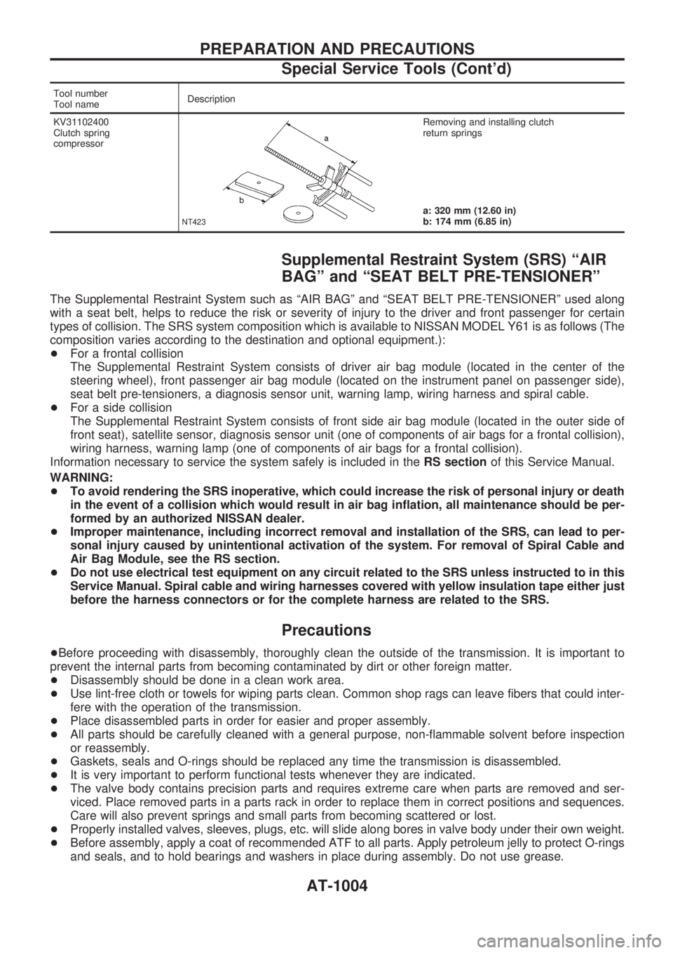
Tool number
Tool nameDescription
KV31102400
Clutch spring
compressor
NT423
Removing and installing clutch
return springs
a: 320 mm (12.60 in)
b: 174 mm (6.85 in)
Supplemental Restraint System (SRS) ªAIR
BAGº and ªSEAT BELT PRE-TENSIONERº
The Supplemental Restraint System such as ªAIR BAGº and ªSEAT BELT PRE-TENSIONERº used along
with a seat belt, helps to reduce the risk or severity of injury to the driver and front passenger for certain
types of collision. The SRS system composition which is available to NISSAN MODEL Y61 is as follows (The
composition varies according to the destination and optional equipment.):
+For a frontal collision
The Supplemental Restraint System consists of driver air bag module (located in the center of the
steering wheel), front passenger air bag module (located on the instrument panel on passenger side),
seat belt pre-tensioners, a diagnosis sensor unit, warning lamp, wiring harness and spiral cable.
+For a side collision
The Supplemental Restraint System consists of front side air bag module (located in the outer side of
front seat), satellite sensor, diagnosis sensor unit (one of components of air bags for a frontal collision),
wiring harness, warning lamp (one of components of air bags for a frontal collision).
Information necessary to service the system safely is included in theRS sectionof this Service Manual.
WARNING:
+To avoid rendering the SRS inoperative, which could increase the risk of personal injury or death
in the event of a collision which would result in air bag inflation, all maintenance should be per-
formed by an authorized NISSAN dealer.
+Improper maintenance, including incorrect removal and installation of the SRS, can lead to per-
sonal injury caused by unintentional activation of the system. For removal of Spiral Cable and
Air Bag Module, see the RS section.
+Do not use electrical test equipment on any circuit related to the SRS unless instructed to in this
Service Manual. Spiral cable and wiring harnesses covered with yellow insulation tape either just
before the harness connectors or for the complete harness are related to the SRS.
Precautions
+Before proceeding with disassembly, thoroughly clean the outside of the transmission. It is important to
prevent the internal parts from becoming contaminated by dirt or other foreign matter.
+Disassembly should be done in a clean work area.
+Use lint-free cloth or towels for wiping parts clean. Common shop rags can leave fibers that could inter-
fere with the operation of the transmission.
+Place disassembled parts in order for easier and proper assembly.
+All parts should be carefully cleaned with a general purpose, non-flammable solvent before inspection
or reassembly.
+Gaskets, seals and O-rings should be replaced any time the transmission is disassembled.
+It is very important to perform functional tests whenever they are indicated.
+The valve body contains precision parts and requires extreme care when parts are removed and ser-
viced. Place removed parts in a parts rack in order to replace them in correct positions and sequences.
Care will also prevent springs and small parts from becoming scattered or lost.
+Properly installed valves, sleeves, plugs, etc. will slide along bores in valve body under their own weight.
+Before assembly, apply a coat of recommended ATF to all parts. Apply petroleum jelly to protect O-rings
and seals, and to hold bearings and washers in place during assembly. Do not use grease.
PREPARATION AND PRECAUTIONS
Special Service Tools (Cont'd)
AT-1004
Page 62 of 1033
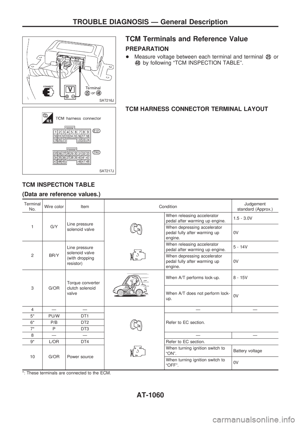
TCM Terminals and Reference Value
PREPARATION
+Measure voltage between each terminal and terminalV25or
V48by following ªTCM INSPECTION TABLEº.
TCM HARNESS CONNECTOR TERMINAL LAYOUT
TCM INSPECTION TABLE
(Data are reference values.)
Terminal
No.Wire color Item ConditionJudgement
standard (Approx.)
1 G/YLine pressure
solenoid valve
When releasing accelerator
pedal after warming up engine.1.5 - 3.0V
When depressing accelerator
pedal fully after warming up
engine.0V
2 BR/YLine pressure
solenoid valve
(with dropping
resistor)When releasing accelerator
pedal after warming up engine.5 - 14V
When depressing accelerator
pedal fully after warming up
engine.0V
3 G/ORTorque converter
clutch solenoid
valve
When A/T performs lock-up. 8 - 15V
When A/T does not perform lock-
up.0V
4Ð Ð
ÐÐ
5* PU/W DT1
Refer to EC section. 6* P/B DT2
7* P DT3
8Ð Ð Ð Ð
9* L/OR DT4 Refer to EC section.
10 G/OR Power sourceWhen turning ignition switch to
ªONº.Battery voltage
When turning ignition switch to
ªOFFº.0V
*: These terminals are connected to the ECM.
SAT216J
SAT217J
TROUBLE DIAGNOSIS Ð General Description
AT-1060
Page 66 of 1033
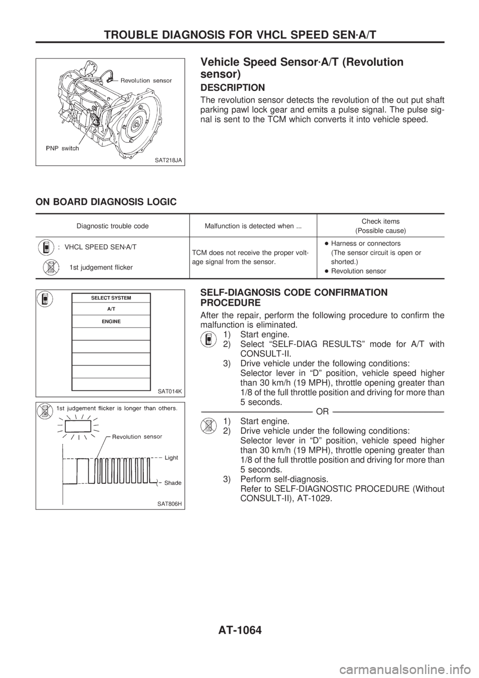
Vehicle Speed SensorzA/T (Revolution
sensor)
DESCRIPTION
The revolution sensor detects the revolution of the out put shaft
parking pawl lock gear and emits a pulse signal. The pulse sig-
nal is sent to the TCM which converts it into vehicle speed.
ON BOARD DIAGNOSIS LOGIC
Diagnostic trouble code Malfunction is detected when ...Check items
(Possible cause)
: VHCL SPEED SENzA/T
TCM does not receive the proper volt-
age signal from the sensor.+Harness or connectors
(The sensor circuit is open or
shorted.)
+Revolution sensor
: 1st judgement flicker
SELF-DIAGNOSIS CODE CONFIRMATION
PROCEDURE
After the repair, perform the following procedure to confirm the
malfunction is eliminated.
1) Start engine.
2) Select ªSELF-DIAG RESULTSº mode for A/T with
CONSULT-II.
3) Drive vehicle under the following conditions:
Selector lever in ªDº position, vehicle speed higher
than 30 km/h (19 MPH), throttle opening greater than
1/8 of the full throttle position and driving for more than
5 seconds.
-------------------------------------------------------------------------------------------------------------------------------------------------------------------------------------------------------------------------------------------------OR-------------------------------------------------------------------------------------------------------------------------------------------------------------------------------------------------------------------------------------------------
1) Start engine.
2) Drive vehicle under the following conditions:
Selector lever in ªDº position, vehicle speed higher
than 30 km/h (19 MPH), throttle opening greater than
1/8 of the full throttle position and driving for more than
5 seconds.
3) Perform self-diagnosis.
Refer to SELF-DIAGNOSTIC PROCEDURE (Without
CONSULT-II), AT-1029.
SAT218JA
SAT014K
SAT806H
TROUBLE DIAGNOSIS FOR VHCL SPEED SENzA/T
AT-1064
Page 67 of 1033
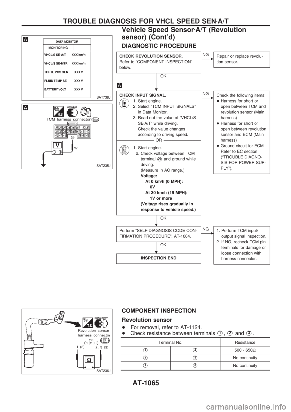
DIAGNOSTIC PROCEDURE
CHECK REVOLUTION SENSOR.
Refer to ªCOMPONENT INSPECTIONº
below.
OK
cNG
Repair or replace revolu-
tion sensor.
CHECK INPUT SIGNAL.
1. Start engine.
2. Select ªTCM INPUT SIGNALSº
in Data Monitor.
3. Read out the value of ªVHCL/S
SEzA/Tº while driving.
Check the value changes
according to driving speed.
------------------------------------------------------------------------------------------------------------------------------------OR------------------------------------------------------------------------------------------------------------------------------------
1. Start engine.
2. Check voltage between TCM
terminal
V29and ground while
driving.
(Measure in AC range.)
Voltage:
At 0 km/h (0 MPH):
0V
At 30 km/h (19 MPH):
1V or more
(Voltage rises gradually in
response to vehicle speed.)
OK
cNG
Check the following items:
+Harness for short or
open between TCM and
revolution sensor (Main
harness)
+Harness for short or
open between revolution
sensor and ECM (Main
harness)
+Ground circuit for ECM
Refer to EC section
(ªTROUBLE DIAGNO-
SIS FOR POWER SUP-
PLYº).
Perform ªSELF-DIAGNOSIS CODE CON-
FIRMATION PROCEDUREº, AT-1064.
OK
cNG
1. Perform TCM input/
output signal inspection.
2. If NG, recheck TCM pin
terminals for damage or
loose connection with
harness connector.
INSPECTION END
COMPONENT INSPECTION
Revolution sensor
+For removal, refer to AT-1124.
+Check resistance between terminals
V1,V2andV3.
Terminal No. Resistance
V1V2500 - 650W
V2V3No continuity
V1V3No continuity
SAT738J
SAT235J
SAT236J
.
.
.
TROUBLE DIAGNOSIS FOR VHCL SPEED SENzA/T
Vehicle Speed SensorzA/T (Revolution
sensor) (Cont'd)
AT-1065
Page 68 of 1033
Vehicle Speed SensorzMTR
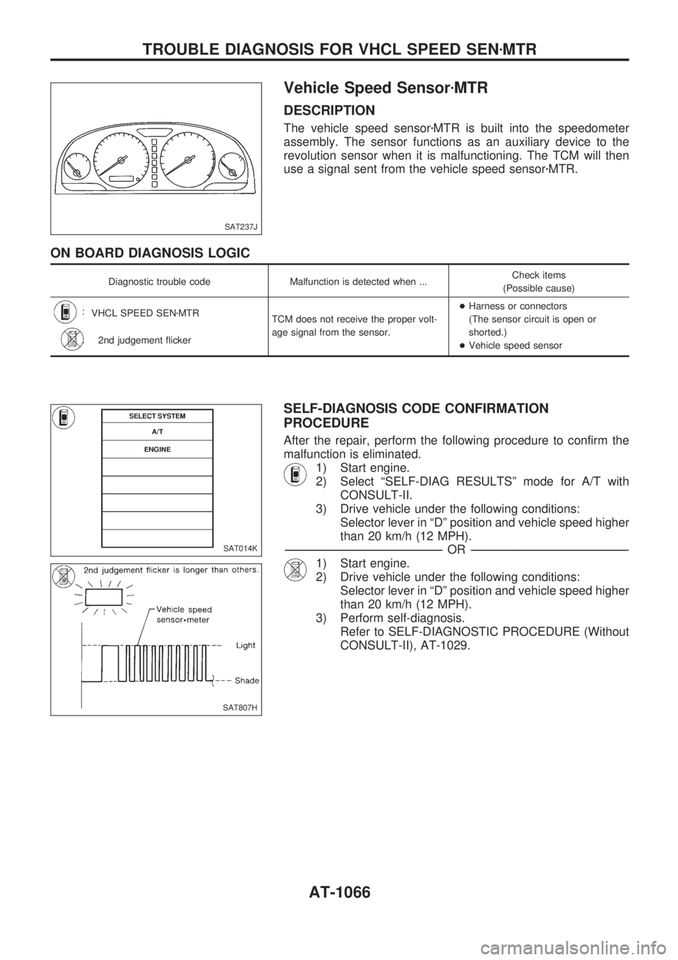
DESCRIPTION
The vehicle speed sensorzMTR is built into the speedometer
assembly. The sensor functions as an auxiliary device to the
revolution sensor when it is malfunctioning. The TCM will then
use a signal sent from the vehicle speed sensorzMTR.
ON BOARD DIAGNOSIS LOGIC
Diagnostic trouble code Malfunction is detected when ...Check items
(Possible cause)
:
VHCL SPEED SENzMTR
TCM does not receive the proper volt-
age signal from the sensor.+Harness or connectors
(The sensor circuit is open or
shorted.)
+Vehicle speed sensor
:
2nd judgement flicker
SELF-DIAGNOSIS CODE CONFIRMATION
PROCEDURE
After the repair, perform the following procedure to confirm the
malfunction is eliminated.
1) Start engine.
2) Select ªSELF-DIAG RESULTSº mode for A/T with
CONSULT-II.
3) Drive vehicle under the following conditions:
Selector lever in ªDº position and vehicle speed higher
than 20 km/h (12 MPH).
-------------------------------------------------------------------------------------------------------------------------------------------------------------------------------------------------------------------------------------------------OR-------------------------------------------------------------------------------------------------------------------------------------------------------------------------------------------------------------------------------------------------
1) Start engine.
2) Drive vehicle under the following conditions:
Selector lever in ªDº position and vehicle speed higher
than 20 km/h (12 MPH).
3) Perform self-diagnosis.
Refer to SELF-DIAGNOSTIC PROCEDURE (Without
CONSULT-II), AT-1029.
SAT237J
SAT014K
SAT807H
TROUBLE DIAGNOSIS FOR VHCL SPEED SENzMTR
AT-1066
Page 69 of 1033
DIAGNOSTIC PROCEDURE
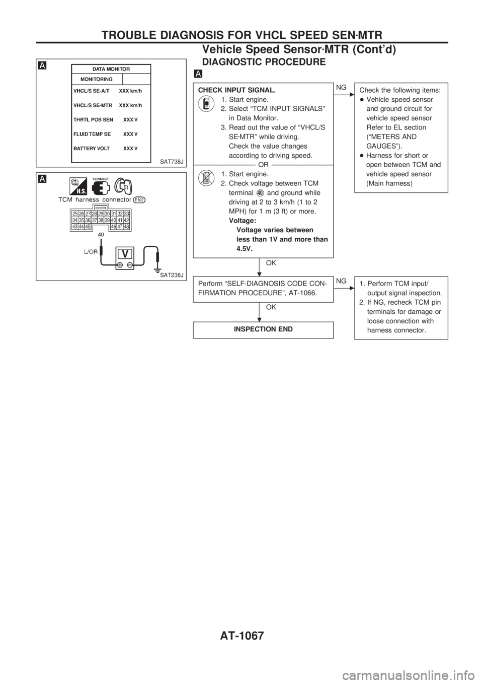
CHECK INPUT SIGNAL.
1. Start engine.
2. Select ªTCM INPUT SIGNALSº
in Data Monitor.
3. Read out the value of ªVHCL/S
SEzMTRº while driving.
Check the value changes
according to driving speed.
------------------------------------------------------------------------------------------------------------------------------------OR------------------------------------------------------------------------------------------------------------------------------------
1. Start engine.
2. Check voltage between TCM
terminal
V40and ground while
driving at 2 to 3 km/h (1 to 2
MPH) for1m(3ft)ormore.
Voltage:
Voltage varies between
less than 1V and more than
4.5V.
OK
cNG
Check the following items:
+Vehicle speed sensor
and ground circuit for
vehicle speed sensor
Refer to EL section
(ªMETERS AND
GAUGESº).
+Harness for short or
open between TCM and
vehicle speed sensor
(Main harness)
Perform ªSELF-DIAGNOSIS CODE CON-
FIRMATION PROCEDUREº, AT-1066.
OK
cNG
1. Perform TCM input/
output signal inspection.
2. If NG, recheck TCM pin
terminals for damage or
loose connection with
harness connector.
INSPECTION END
SAT738J
SAT238J.
.
TROUBLE DIAGNOSIS FOR VHCL SPEED SENzMTR
Vehicle Speed SensorzMTR (Cont'd)
AT-1067
Page 70 of 1033
Accelerator Position Sensor
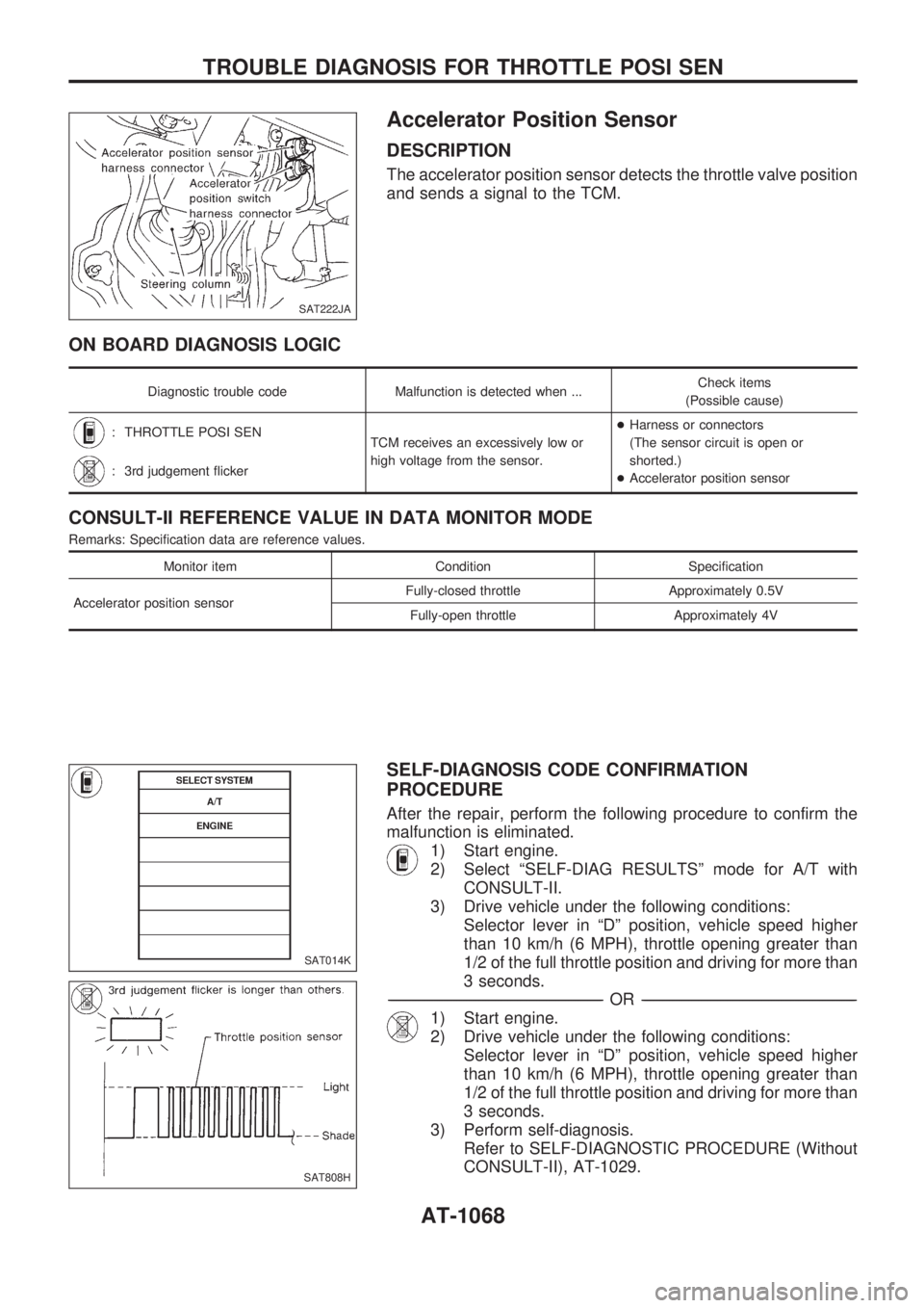
DESCRIPTION
The accelerator position sensor detects the throttle valve position
and sends a signal to the TCM.
ON BOARD DIAGNOSIS LOGIC
Diagnostic trouble code Malfunction is detected when ...Check items
(Possible cause)
: THROTTLE POSI SEN
TCM receives an excessively low or
high voltage from the sensor.+Harness or connectors
(The sensor circuit is open or
shorted.)
+Accelerator position sensor
: 3rd judgement flicker
CONSULT-II REFERENCE VALUE IN DATA MONITOR MODE
Remarks: Specification data are reference values.
Monitor item Condition Specification
Accelerator position sensorFully-closed throttle Approximately 0.5V
Fully-open throttle Approximately 4V
SELF-DIAGNOSIS CODE CONFIRMATION
PROCEDURE
After the repair, perform the following procedure to confirm the
malfunction is eliminated.
1) Start engine.
2) Select ªSELF-DIAG RESULTSº mode for A/T with
CONSULT-II.
3) Drive vehicle under the following conditions:
Selector lever in ªDº position, vehicle speed higher
than 10 km/h (6 MPH), throttle opening greater than
1/2 of the full throttle position and driving for more than
3 seconds.
-------------------------------------------------------------------------------------------------------------------------------------------------------------------------------------------------------------------------------------------------OR-------------------------------------------------------------------------------------------------------------------------------------------------------------------------------------------------------------------------------------------------
1) Start engine.
2) Drive vehicle under the following conditions:
Selector lever in ªDº position, vehicle speed higher
than 10 km/h (6 MPH), throttle opening greater than
1/2 of the full throttle position and driving for more than
3 seconds.
3) Perform self-diagnosis.
Refer to SELF-DIAGNOSTIC PROCEDURE (Without
CONSULT-II), AT-1029.
SAT222JA
SAT014K
SAT808H
TROUBLE DIAGNOSIS FOR THROTTLE POSI SEN
AT-1068
Page 71 of 1033
![NISSAN PATROL 2000 Electronic Repair Manual DIAGNOSTIC PROCEDURE
Perform diagnostic test mode II (self-
diagnostic results) for engine control.
Refer to EC section [ªMalfunction Indica-
tor (MI)º, ªON BOARD DIAGNOSTIC
SYSTEM DESCRIPTIONº].
NISSAN PATROL 2000 Electronic Repair Manual DIAGNOSTIC PROCEDURE
Perform diagnostic test mode II (self-
diagnostic results) for engine control.
Refer to EC section [ªMalfunction Indica-
tor (MI)º, ªON BOARD DIAGNOSTIC
SYSTEM DESCRIPTIONº].](/manual-img/5/57367/w960_57367-70.png)
DIAGNOSTIC PROCEDURE
Perform diagnostic test mode II (self-
diagnostic results) for engine control.
Refer to EC section [ªMalfunction Indica-
tor (MI)º, ªON BOARD DIAGNOSTIC
SYSTEM DESCRIPTIONº].
OK
cNG
Check accelerator position
sensor circuit for engine
control. Refer to EC sec-
tion [ªTROUBLE DIAGNO-
SIS FOR ªTHRTL
(ACCEL) POSI SENº
(DTC 43)].
CHECK INPUT SIGNAL.
1. Turn ignition switch to ªONº
position.
(Do not start engine.)
2. Select ªTCM INPUT SIGNALSº
in Data Monitor.
3. Read out the value of ªTHRTL
POS SENº.
Voltage:
Fully-closed throttle:
Approximately 0.5V
Fully-open throttle:
Approximately 4V
------------------------------------------------------------------------------------------------------------------------------------OR------------------------------------------------------------------------------------------------------------------------------------
1. Turn ignition switch to ªONº
position. (Do not start engine.)
2. Check voltage between TCM
terminals
V41andV42while
accelerator pedal is depressed
slowly.
Voltage:
Fully-closed throttle valve:
Approximately 0.5 - 0.7V
Fully-open throttle valve:
Approximately 4V
(Voltage rises gradually in
response to throttle position)
OK
cNG
Check harness for short or
open between ECM and
TCM regarding accelerator
position sensor circuit.
(Main harness)
CHECK ACCELERATOR POSITION
SWITCH.
Refer to ªCHECK ACCELERATOR POSI-
TION SWITCHº, AT-1091.
OK
cNG
Repair or replace dam-
aged parts.
Perform ªSELF-DIAGNOSIS CODE CON-
FIRMATION PROCEDUREº, AT-1068.
OK
cNG
1. Perform TCM input/
output signal inspection.
2. If NG, recheck TCM pin
terminals for damage or
loose connection with
harness connector.
INSPECTION END
SAT738J
SAT239J
.
.
.
.
TROUBLE DIAGNOSIS FOR THROTTLE POSI SEN
Accelerator Position Sensor (Cont'd)
AT-1069