2000 NISSAN PATROL service
[x] Cancel search: servicePage 2 of 1033

FOREWORD
This manual contains maintenance and repair procedures for NISSAN
PATROL GR,modelY61 series.
In order to assure your safety and the efficient functioning of the vehicle,
this manual should be read thoroughly. It is especially important that the
PRECAUTIONS in the GI section be completely understood before starting
any repair task.
All information in this manual is based on the latest product information
at the time of publication. The right is reserved to make changes in speci-
®cations and methods at any time without notice.
IMPORTANT SAFETY NOTICE
The proper performance of service is essential for both the safety of the
technician and the efficient functioning of the vehicle.
The service methods in this Service Manual are described in such a man-
ner that the service may be performed safely and accurately.
Service varies with the procedures used, the skills of the technician and the
tools and parts available. Accordingly, anyone using service procedures,
tools or parts which are not speci®cally recommended by NISSAN must
®rst completely satisfy himself that neither his safety nor the vehicle's
safety will be jeopardized by the service method selected.
NISSAN EUROPE S.A.S.
Service Engineering SectionParis, France
Page 3 of 1033

AUTOMATIC TRANSMISSION
SECTION
AT
CONTENTS
PREPARATION AND PRECAUTIONS............... 1003
Special Service Tools ...................................... 1003
Supplemental Restraint System (SRS) ªAIR
BAGº and ªSEAT BELT PRE-TENSIONERº ... 1004
Precautions ...................................................... 1004
Service Notice or Precautions ......................... 1006
OVERALL SYSTEM............................................ 1007
A/T Electrical Parts Location ........................... 1007
Circuit Diagram ................................................ 1008
Wiring Diagram Ð A/T Ð ................................ 1009
Cross-sectional View ....................................... 1022
Hydraulic Control Circuits ................................ 1023
Shift Mechanism .............................................. 1024
Control System ................................................ 1026
ON BOARD DIAGNOSTIC SYSTEM
DESCRIPTION..................................................... 1028
Self-diagnosis................................................... 1028
Diagnosis by CONSULT-II ............................... 1034
TROUBLE DIAGNOSIS Ð Introduction............ 1036
Introduction ...................................................... 1036
Diagnostic Worksheet ...................................... 1037
Work Flow ........................................................ 1040
TROUBLE DIAGNOSIS Ð Basic Inspection.... 1041
A/T Fluid Check ............................................... 1041
Stall Test .......................................................... 1041
Line Pressure Test........................................... 1044
Road Test ........................................................ 1046
TROUBLE DIAGNOSIS Ð General
Description.......................................................... 1057
Symptom Chart ................................................ 1057
TCM Terminals and Reference Value ............. 1060
TROUBLE DIAGNOSIS FOR VHCL SPEED
SENzA/T................................................................ 1064Vehicle Speed SensorzA/T (Revolution
sensor) ............................................................. 1064
TROUBLE DIAGNOSIS FOR VHCL SPEED
SENzMTR.............................................................. 1066
Vehicle Speed SensorzzMTR ............................ 1066
TROUBLE DIAGNOSIS FOR THROTTLE POSI
SEN...................................................................... 1068
Accelerator Position Sensor ............................ 1068
TROUBLE DIAGNOSIS FOR SHIFT
SOLENOID/V A.................................................... 1070
Shift Solenoid Valve A ..................................... 1070
TROUBLE DIAGNOSIS FOR SHIFT
SOLENOID/V B.................................................... 1072
Shift Solenoid Valve B ..................................... 1072
TROUBLE DIAGNOSIS FOR OVERRUN
CLUTCH S/V........................................................ 1074
Overrun Clutch Solenoid Valve ....................... 1074
TROUBLE DIAGNOSIS FOR T/C CLUTCH
SOL/V................................................................... 1076
Torque Converter Clutch Solenoid Valve ........ 1076
TROUBLE DIAGNOSIS FOR BATT/FLUID
TEMP SEN........................................................... 1079
A/T Fluid Temperature Sensor and TCM
Power Source .................................................. 1079
TROUBLE DIAGNOSIS FOR ENGINE SPEED
SIG....................................................................... 1082
Engine Speed Signal ....................................... 1082
TROUBLE DIAGNOSIS FOR LINE PRESSURE
S/V........................................................................ 1084
Line Pressure Solenoid Valve ......................... 1084
TROUBLE DIAGNOSIS FOR CONTROL UNIT
(RAM), CONTROL UNIT (ROM)......................... 1087
Description ....................................................... 1087
AT
Page 4 of 1033

Diagnostic Procedure....................................... 1088
TROUBLE DIAGNOSIS FOR CONTROL UNIT
(EFP ROM)........................................................... 1089
Description ....................................................... 1089
Diagnostic Procedure....................................... 1090
TROUBLE DIAGNOSIS FOR
NON-DETECTABLE ITEMS................................ 1091
PNP, Overdrive Control, A/T Mode or
Accelerator Position Switches ......................... 1091
DIAGNOSTIC PROCEDURES FOR
SYMPTOMS......................................................... 1097
1. SPORT Indicator Lamp Does Not
Come On.......................................................... 1097
2. SPORT Indicator Lamp Does Not
Come On.......................................................... 1098
3. O/D OFF Indicator Lamp Does Not Come
On .................................................................... 1098
4. SPORT Indicator Lamp Does Not
Come On.......................................................... 1099
5. Engine Cannot Be Started In ªPº and ªNº
Position ............................................................ 1100
6. In ªPº Position, Vehicle Moves Forward Or
Backward When Pushed ................................. 1100
7. In ªNº Position, Vehicle Moves .................... 1101
8. Large Shock. ªNº®ªRº Position ................ 1102
9. Vehicle Does Not Creep Backward In ªRº
Position ............................................................ 1103
10. Vehicle Does Not Creep Forward In ªDº,
ª2º Or ª1º Position ............................................ 1104
11. Vehicle Cannot Be Started From D
1......... 1105
12. A/T Does Not Shift: D
1®D2Or Does Not
Kickdown: D
4®D2......................................... 1106
13. A/T Does Not Shift: D
2®D3.................... 1107
14. A/T Does Not Shift: D
3®D4.................... 1108
15. A/T Does Not Perform Lock-up ................. 1109
16. A/T Does Not Hold Lock-up Condition ...... 1110
17. Lock-up Is Not Released ........................... 1110
18. Engine Speed Does Not Return To Idle
(Light Braking D
4®D3) .................................. 1111
19. Vehicle Does Not Start From D
1............... 1112
20. A/T Does Not Shift: D
2®D1When
Depressing Accelerator Pedal ......................... 1113
21. A/T Does Not Shift: D
4®D3, When
Overdrive Control Switch ªONº®ªOFFº ........ 1114
22. A/T Does Not Shift: D
3®22, When
Selector Lever ªDº®ª2º Position ................... 1114
23. A/T Does Not Shift: 2
2®11, WhenSelector Lever ª2º®ª1º Position .................... 1115
24. Vehicle Does Not Decelerate By Engine
Brake ................................................................ 1115
TROUBLE DIAGNOSES Ð A/T Shift Lock
System................................................................. 1116
Description ....................................................... 1116
Wiring Diagram Ð SHIFT Ð ........................... 1117
Diagnostic Procedure....................................... 1118
Key Interlock Cable.......................................... 1121
Component Check ........................................... 1122
ON-VEHICLE SERVICE...................................... 1124
Control Valve Assembly and Accumulators .... 1124
Revolution Sensor Replacement ..................... 1125
Rear Oil Seal Replacement ............................. 1125
Parking Pawl Components Inspection ............. 1125
PNP Switch Adjustment ................................... 1125
Manual Control Linkage Adjustment................ 1126
REMOVAL AND INSTALLATION....................... 1127
Removal ........................................................... 1127
Installation ........................................................ 1128
MAJOR OVERHAUL........................................... 1129
Oil Channel ...................................................... 1131
Locations of Needle Bearings, Thrust Washers
and Snap Rings ............................................... 1132
DISASSEMBLY.................................................... 1133
REPAIR FOR COMPONENT PARTS................. 1144
Oil Pump .......................................................... 1144
Control Valve Assembly................................... 1148
Control Valve Upper Body ............................... 1154
Control Valve Lower Body ............................... 1159
Reverse Clutch ................................................ 1161
High Clutch ...................................................... 1165
Forward and Overrun Clutches ....................... 1167
Low & Reverse Brake ...................................... 1171
Forward Clutch Drum Assembly ...................... 1175
Rear Internal Gear and Forward Clutch Hub .. 1177
Band Servo Piston Assembly .......................... 1180
Parking Pawl Components .............................. 1184
ASSEMBLY.......................................................... 1186
Assembly (1) .................................................... 1186
Adjustment ....................................................... 1190
Assembly (2) .................................................... 1195
A/T FLUID COOLER SYSTEM........................... 1205
A/T Fluid Cooler ............................................... 1205
SERVICE DATA AND SPECIFICATIONS (SDS)1206
General Specifications ..................................... 1206
Specifications and Adjustment......................... 1206
When you read wiring diagrams:
+Read GI section, ªHOW TO READ WIRING DIAGRAMSº.
+See EL section, ªPOWER SUPPLY ROUTINGº for power distribution circuit.
When you perform trouble diagnoses, read GI section, ªHOW TO FOLLOW FLOW
CHART IN TROUBLE DIAGNOSESº.
AT-1002
Page 5 of 1033
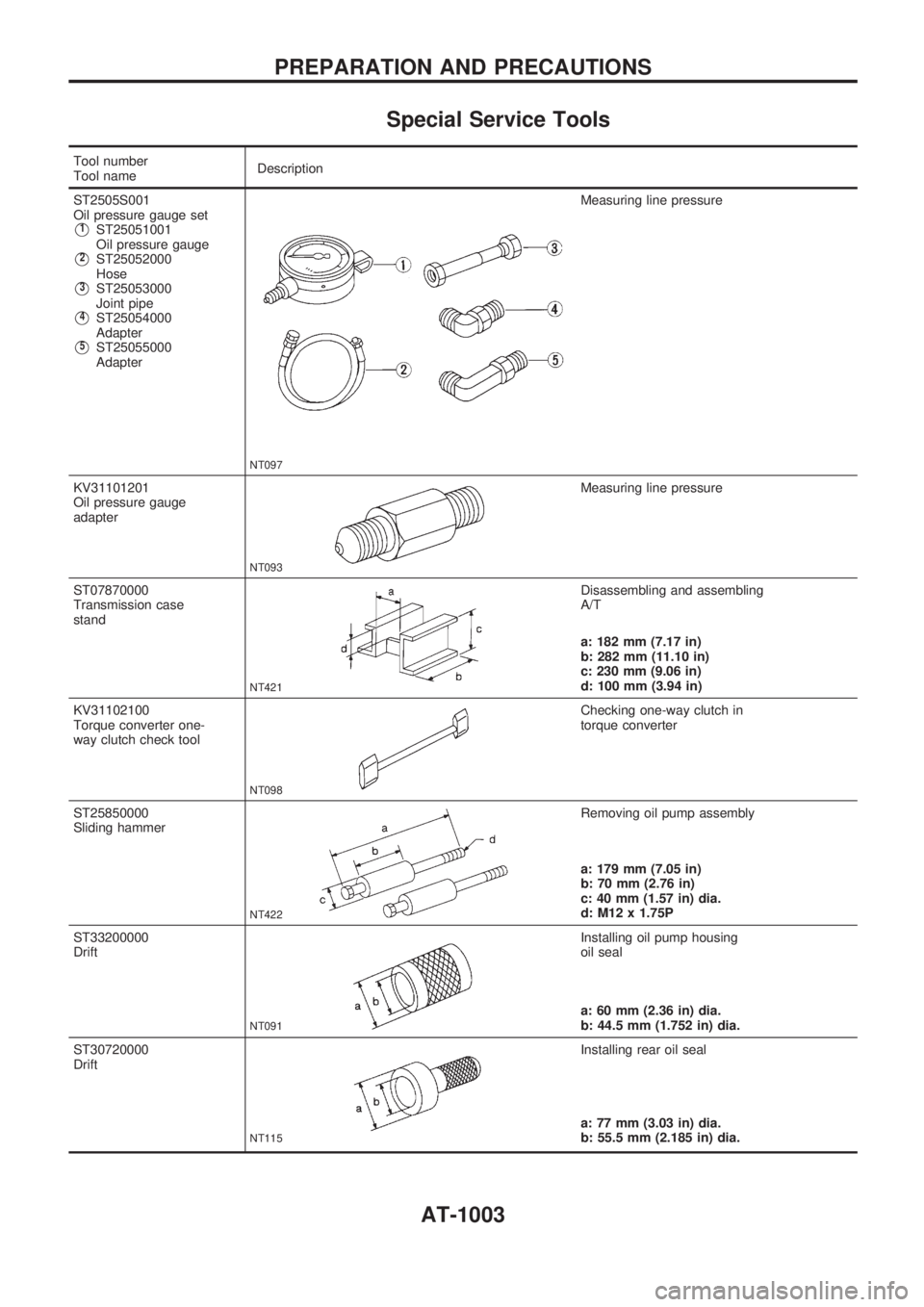
Special Service Tools
Tool number
Tool nameDescription
ST2505S001
Oil pressure gauge set
V1ST25051001
Oil pressure gauge
V2ST25052000
Hose
V3ST25053000
Joint pipe
V4ST25054000
Adapter
V5ST25055000
Adapter
NT097
Measuring line pressure
KV31101201
Oil pressure gauge
adapter
NT093
Measuring line pressure
ST07870000
Transmission case
stand
NT421
Disassembling and assembling
A/T
a: 182 mm (7.17 in)
b: 282 mm (11.10 in)
c: 230 mm (9.06 in)
d: 100 mm (3.94 in)
KV31102100
Torque converter one-
way clutch check tool
NT098
Checking one-way clutch in
torque converter
ST25850000
Sliding hammer
NT422
Removing oil pump assembly
a: 179 mm (7.05 in)
b: 70 mm (2.76 in)
c: 40 mm (1.57 in) dia.
d: M12 x 1.75P
ST33200000
Drift
NT091
Installing oil pump housing
oil seal
a: 60 mm (2.36 in) dia.
b: 44.5 mm (1.752 in) dia.
ST30720000
Drift
NT115
Installing rear oil seal
a: 77 mm (3.03 in) dia.
b: 55.5 mm (2.185 in) dia.
PREPARATION AND PRECAUTIONS
AT-1003
Page 6 of 1033
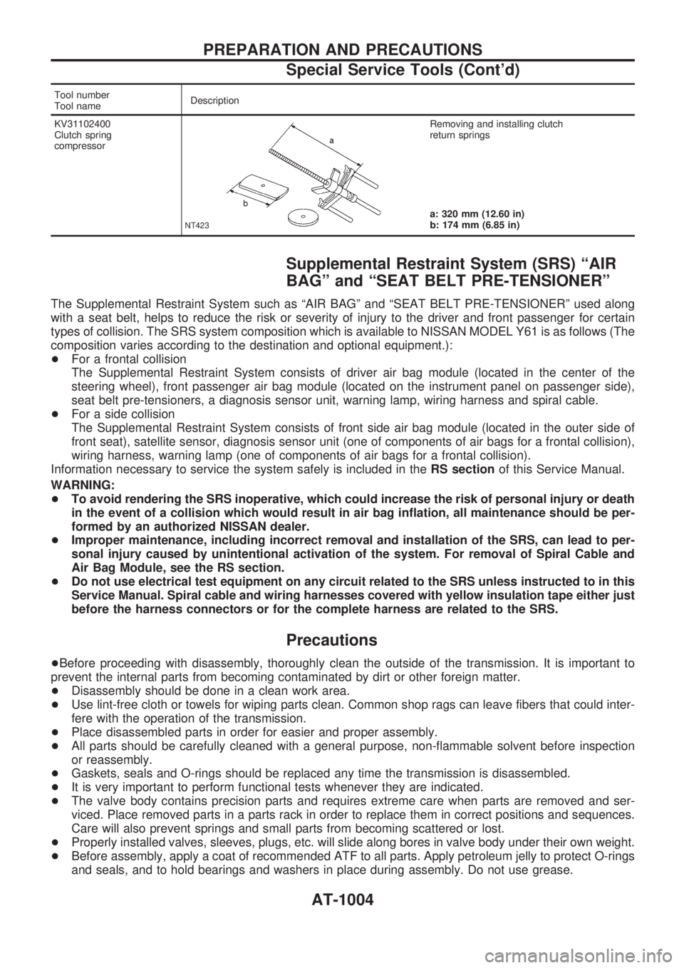
Tool number
Tool nameDescription
KV31102400
Clutch spring
compressor
NT423
Removing and installing clutch
return springs
a: 320 mm (12.60 in)
b: 174 mm (6.85 in)
Supplemental Restraint System (SRS) ªAIR
BAGº and ªSEAT BELT PRE-TENSIONERº
The Supplemental Restraint System such as ªAIR BAGº and ªSEAT BELT PRE-TENSIONERº used along
with a seat belt, helps to reduce the risk or severity of injury to the driver and front passenger for certain
types of collision. The SRS system composition which is available to NISSAN MODEL Y61 is as follows (The
composition varies according to the destination and optional equipment.):
+For a frontal collision
The Supplemental Restraint System consists of driver air bag module (located in the center of the
steering wheel), front passenger air bag module (located on the instrument panel on passenger side),
seat belt pre-tensioners, a diagnosis sensor unit, warning lamp, wiring harness and spiral cable.
+For a side collision
The Supplemental Restraint System consists of front side air bag module (located in the outer side of
front seat), satellite sensor, diagnosis sensor unit (one of components of air bags for a frontal collision),
wiring harness, warning lamp (one of components of air bags for a frontal collision).
Information necessary to service the system safely is included in theRS sectionof this Service Manual.
WARNING:
+To avoid rendering the SRS inoperative, which could increase the risk of personal injury or death
in the event of a collision which would result in air bag inflation, all maintenance should be per-
formed by an authorized NISSAN dealer.
+Improper maintenance, including incorrect removal and installation of the SRS, can lead to per-
sonal injury caused by unintentional activation of the system. For removal of Spiral Cable and
Air Bag Module, see the RS section.
+Do not use electrical test equipment on any circuit related to the SRS unless instructed to in this
Service Manual. Spiral cable and wiring harnesses covered with yellow insulation tape either just
before the harness connectors or for the complete harness are related to the SRS.
Precautions
+Before proceeding with disassembly, thoroughly clean the outside of the transmission. It is important to
prevent the internal parts from becoming contaminated by dirt or other foreign matter.
+Disassembly should be done in a clean work area.
+Use lint-free cloth or towels for wiping parts clean. Common shop rags can leave fibers that could inter-
fere with the operation of the transmission.
+Place disassembled parts in order for easier and proper assembly.
+All parts should be carefully cleaned with a general purpose, non-flammable solvent before inspection
or reassembly.
+Gaskets, seals and O-rings should be replaced any time the transmission is disassembled.
+It is very important to perform functional tests whenever they are indicated.
+The valve body contains precision parts and requires extreme care when parts are removed and ser-
viced. Place removed parts in a parts rack in order to replace them in correct positions and sequences.
Care will also prevent springs and small parts from becoming scattered or lost.
+Properly installed valves, sleeves, plugs, etc. will slide along bores in valve body under their own weight.
+Before assembly, apply a coat of recommended ATF to all parts. Apply petroleum jelly to protect O-rings
and seals, and to hold bearings and washers in place during assembly. Do not use grease.
PREPARATION AND PRECAUTIONS
Special Service Tools (Cont'd)
AT-1004
Page 8 of 1033
Service Notice or Precautions
FAIL-SAFE
The TCM has an electronic Fail-Safe (limp home mode). This allows the vehicle to be driven even if a major
electrical input/output device circuit is damaged.
Under Fail-Safe, the vehicle always runs in third gear even with a shift lever position of ª1º, ª2º or ªDº. Cus-
tomer may complain of ªsluggish or poor accelerationº.
When the Fail-Safe operation occurs the next time the key is turned to the ªONº position, the SPORT indi-
cator lamp will blink for about 8 seconds. (For diagnosis, refer to AT-1029.)
The blinking of the SPORT indicator lamp for about 8 seconds will appear only once and be cleared. The
customer may resume normal driving conditions by chance.
Always follow the ªWORK FLOWº (Refer to AT-1040).
The SELF-DIAGNOSIS results will be as follows:
The first SELF-DIAGNOSIS will indicate the damage of the vehicle speed sensor or the revolution
sensor.
During the next SELF-DIAGNOSIS performed after checking the sensor, no damages will be indicated.
PREPARATION AND PRECAUTIONS
AT-1006
Page 36 of 1033
Diagnosis by CONSULT-II
NOTICE
1.The CONSULT-II electrically displays shift timing and lock-up timing (that is, operation timing of each
solenoid).
Check for time difference between actual shift timing and the CONSULT-II display. If the difference is
noticeable, mechanical parts (except solenoids, sensors, etc.) may be malfunctioning. Check mechanical
parts using applicable diagnostic procedures.
2. Shift schedule (which implies gear position) displayed on CONSULT-II and that indicated in Service
Manual may differ slightly. This occurs because of the following reasons:
+Actual shift schedule has more or less tolerance or allowance,
+Shift schedule indicated in Service Manual refers to the point where shifts start. Gear position dis-
played on CONSULT-II indicates the point where shifts are completed.
3. Shift solenoid valve ªAº or ªBº is displayed on CONSULT-II at the start of shifting. Gear position is dis-
played upon completion of shifting (which is computed by TCM).
4. Additional CONSULT-II information can be found in the Operation Manual supplied with the CONSULT-II
unit.
SELF-DIAGNOSTIC RESULT TEST MODE
Refer to AT-1028.
DATA MONITOR DIAGNOSTIC TEST MODE
Item DisplayMonitor item
Description Remarks TCM
input
signalsMain
signals
Vehicle speed sensor 1 (A/T)
(Revolution sensor)VHCL/S SEzA/T
[km/h] or [mph]
XÐ+Vehicle speed computed from
signal of revolution sensor is
displayed.When racing engine in ªNº or ªPº
position with vehicle stationary,
CONSULT data may not indicate
0 km/h (0 MPH).
Vehicle speed sensor 2
(Meter)VHCL/S SEzMTR
[km/h] or [mph]
XÐ+Vehicle speed computed from
signal of vehicle speed sensor
is displayed.Vehicle speed display may not be
accurate under approx. 10 km/h
(6 MPH). It may not indicate 0
km/h (0 MPH) when vehicle is
stationary.
Accelerator position sensor THRTL POS SEN
[V]XÐ+Accelerator position sensor sig-
nal voltage is displayed.
A/T fluid temperature sensor FLUID TEMP SE
[V]
XÐ+A/T fluid temperature sensor
signal voltage is displayed.
+Signal voltage lowers as fluid
temperature rises.
Battery voltage BATTERY VOLT
[V]XÐ+Source voltage of TCM is dis-
played.
Engine speed ENGINE SPEED
[rpm]
XX+Engine speed, computed from
engine speed signal, is dis-
played.Engine speed display may not be
accurate under approx. 800 rpm.
It may not indicate 0 rpm even
when engine is not running.
Overdrive control switch OVERDRIVE SW
[ON/OFF] X Ð+ON/OFF state computed from
signal of overdrive control SW
is displayed.
P/N position switch PN POSI SW
[ON/OFF] X Ð+ON/OFF state computed from
signal of PN position SW is dis-
played.
R position switch R POSITION SW
[ON/OFF] X Ð+ON/OFF state computed from
signal of R position SW is dis-
played.
D position switch D POSITION SW
[ON/OFF] X Ð+ON/OFF state computed from
signal of D position SW is dis-
played.
2 position switch 2 POSITION SW
[ON/OFF] X Ð+ON/OFF status, computed from
signal of 2 position SW, is dis-
played.
ON BOARD DIAGNOSTIC SYSTEM DESCRIPTION
AT-1034
Page 39 of 1033
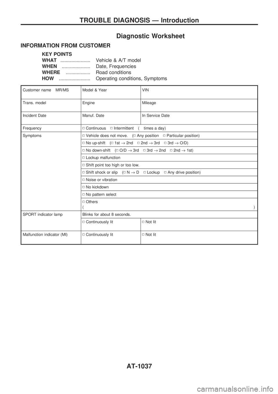
Diagnostic Worksheet
INFORMATION FROM CUSTOMER
KEY POINTS
WHAT...................... Vehicle & A/T model
WHEN..................... Date, Frequencies
WHERE.................. Road conditions
HOW....................... Operating conditions, Symptoms
Customer name MR/MS Model & Year VIN
Trans. model Engine Mileage
Incident Date Manuf. Date In Service Date
FrequencyNContinuousNIntermittent ( times a day)
SymptomsNVehicle does not move. (NAny positionNParticular position)
NNo up-shift (N1st®2ndN2nd®3rdN3rd®O/D)
NNo down-shift (NO/D®3rdN3rd®2ndN2nd®1st)
NLockup malfunction
NShift point too high or too low.
NShift shock or slip (NN®DNLockupNAny drive position)
NNoise or vibration
NNo kickdown
NNo pattern select
NOthers
()
SPORT indicator lamp Blinks for about 8 seconds.
NContinuously litNNot lit
Malfunction indicator (MI)NContinuously litNNot lit
TROUBLE DIAGNOSIS Ð Introduction
AT-1037