2000 NISSAN PATROL steering wheel
[x] Cancel search: steering wheelPage 6 of 1033
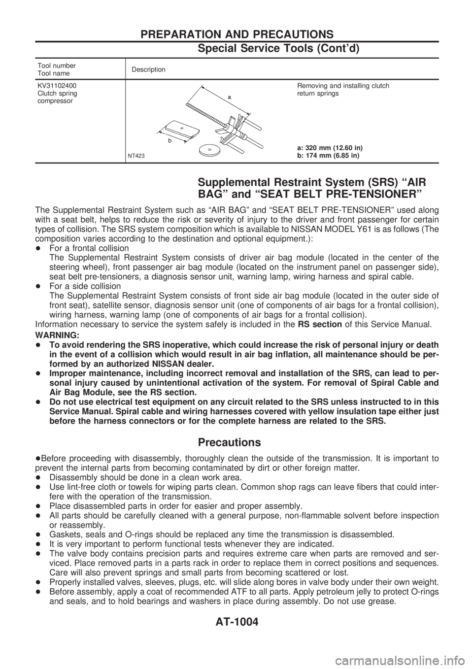
Tool number
Tool nameDescription
KV31102400
Clutch spring
compressor
NT423
Removing and installing clutch
return springs
a: 320 mm (12.60 in)
b: 174 mm (6.85 in)
Supplemental Restraint System (SRS) ªAIR
BAGº and ªSEAT BELT PRE-TENSIONERº
The Supplemental Restraint System such as ªAIR BAGº and ªSEAT BELT PRE-TENSIONERº used along
with a seat belt, helps to reduce the risk or severity of injury to the driver and front passenger for certain
types of collision. The SRS system composition which is available to NISSAN MODEL Y61 is as follows (The
composition varies according to the destination and optional equipment.):
+For a frontal collision
The Supplemental Restraint System consists of driver air bag module (located in the center of the
steering wheel), front passenger air bag module (located on the instrument panel on passenger side),
seat belt pre-tensioners, a diagnosis sensor unit, warning lamp, wiring harness and spiral cable.
+For a side collision
The Supplemental Restraint System consists of front side air bag module (located in the outer side of
front seat), satellite sensor, diagnosis sensor unit (one of components of air bags for a frontal collision),
wiring harness, warning lamp (one of components of air bags for a frontal collision).
Information necessary to service the system safely is included in theRS sectionof this Service Manual.
WARNING:
+To avoid rendering the SRS inoperative, which could increase the risk of personal injury or death
in the event of a collision which would result in air bag inflation, all maintenance should be per-
formed by an authorized NISSAN dealer.
+Improper maintenance, including incorrect removal and installation of the SRS, can lead to per-
sonal injury caused by unintentional activation of the system. For removal of Spiral Cable and
Air Bag Module, see the RS section.
+Do not use electrical test equipment on any circuit related to the SRS unless instructed to in this
Service Manual. Spiral cable and wiring harnesses covered with yellow insulation tape either just
before the harness connectors or for the complete harness are related to the SRS.
Precautions
+Before proceeding with disassembly, thoroughly clean the outside of the transmission. It is important to
prevent the internal parts from becoming contaminated by dirt or other foreign matter.
+Disassembly should be done in a clean work area.
+Use lint-free cloth or towels for wiping parts clean. Common shop rags can leave fibers that could inter-
fere with the operation of the transmission.
+Place disassembled parts in order for easier and proper assembly.
+All parts should be carefully cleaned with a general purpose, non-flammable solvent before inspection
or reassembly.
+Gaskets, seals and O-rings should be replaced any time the transmission is disassembled.
+It is very important to perform functional tests whenever they are indicated.
+The valve body contains precision parts and requires extreme care when parts are removed and ser-
viced. Place removed parts in a parts rack in order to replace them in correct positions and sequences.
Care will also prevent springs and small parts from becoming scattered or lost.
+Properly installed valves, sleeves, plugs, etc. will slide along bores in valve body under their own weight.
+Before assembly, apply a coat of recommended ATF to all parts. Apply petroleum jelly to protect O-rings
and seals, and to hold bearings and washers in place during assembly. Do not use grease.
PREPARATION AND PRECAUTIONS
Special Service Tools (Cont'd)
AT-1004
Page 224 of 1033
Supplemental Restraint System (SRS) ªAIR
BAGº and ªSEAT BELT PRE-TENSIONERº
The Supplemental Restraint System such as ªAIR BAGº and ªSEAT BELT PRE-TENSIONERº used along
with a seat belt, helps to reduce the risk or severity of injury to the driver and front passenger for certain
types of collision. The SRS system composition which is available to NISSAN MODEL Y61 is as follows (The
composition varies according to the destination and optional equipment.):
+For a frontal collision
The Supplemental Restraint System consists of driver air bag module (located in the center of the
steering wheel), front passenger air bag module (located on the instrument panel on passenger side),
seat belt pre-tensioners, a diagnosis sensor unit, warning lamp, wiring harness and spiral cable.
+ For a side collision
The Supplemental Restraint System consists of front side air bag module (located in the outer side of
front seat), satellite sensor, diagnosis sensor unit (one of components of air bags for a frontal collision),
wiring harness, warning lamp (one of components of air bags for a frontal collision).
Information necessary to service the system safely is included in the RS sectionof this Service Manual.
WARNING:
+ To avoid rendering the SRS inoperative, which could increase the risk of personal injury or death
in the event of a collision which would result in air bag inflation, all maintenance should be per-
formed by an authorized NISSAN dealer.
+ Improper maintenance, including incorrect removal and installation of the SRS, can lead to per-
sonal injury caused by intentional activation of the system. For removal of Spiral Cable and Air
Bag Module, see the RS section.
+ Do not use electrical test equipment on any circuit related to the SRS unless instructed to in this
Service Manual. Spiral cable and wiring harnesses covered with yellow insulation tape either just
before the harness connectors or for the complete harness are related to the SRS.
PRECAUTIONS
BT-1002
Page 238 of 1033
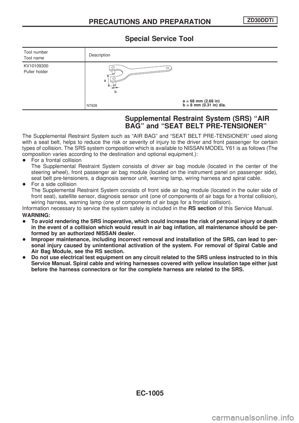
Special Service Tool
Tool number
Tool nameDescription
KV10109300
Puller holder
NT628a = 68 mm (2.68 in)
b = 8 mm (0.31 in) dia.
Supplemental Restraint System (SRS) ªAIR
BAGº and ªSEAT BELT PRE-TENSIONERº
The Supplemental Restraint System such as ªAIR BAGº and ªSEAT BELT PRE-TENSIONERº used along
with a seat belt, helps to reduce the risk or severity of injury to the driver and front passenger for certain
types of collision. The SRS system composition which is available to NISSAN MODEL Y61 is as follows (The
composition varies according to the destination and optional equipment.):
+For a frontal collision
The Supplemental Restraint System consists of driver air bag module (located in the center of the
steering wheel), front passenger air bag module (located on the instrument panel on passenger side),
seat belt pre-tensioners, a diagnosis sensor unit, warning lamp, wiring harness and spiral cable.
+For a side collision
The Supplemental Restraint System consists of front side air bag module (located in the outer side of
front seat), satellite sensor, diagnosis sensor unit (one of components of air bags for a frontal collision),
wiring harness, warning lamp (one of components of air bags for a frontal collision).
Information necessary to service the system safely is included in theRS sectionof this Service Manual.
WARNING:
+To avoid rendering the SRS inoperative, which could increase the risk of personal injury or death
in the event of a collision which would result in air bag inflation, all maintenance should be per-
formed by an authorized NISSAN dealer.
+Improper maintenance, including incorrect removal and installation of the SRS, can lead to per-
sonal injury caused by unintentional activation of the system. For removal of Spiral Cable and
Air Bag Module, see the RS section.
+Do not use electrical test equipment on any circuit related to the SRS unless instructed to in this
Service Manual. Spiral cable and wiring harnesses covered with yellow insulation tape either just
before the harness connectors or for the complete harness are related to the SRS.
PRECAUTIONS AND PREPARATIONZD30DDTi
EC-1005
Page 282 of 1033
Basic Inspection
Precaution:
Perform Basic Inspection without electrical or mechanical
loads applied;
+Shift lever is in neutral position,
+Heat up switch is OFF,
+Headlamp switch is OFF,
+Air conditioner switch is OFF,
+Rear defogger switch is OFF,
+Steering wheel is in the straight-ahead position, etc.
1 INSPECTION START
1. Check service records for any recent repairs that may indicate a related problem.
2. Check the current need for scheduled maintenance, especially for fuel filter and air cleaner filter. Refer to MA section.
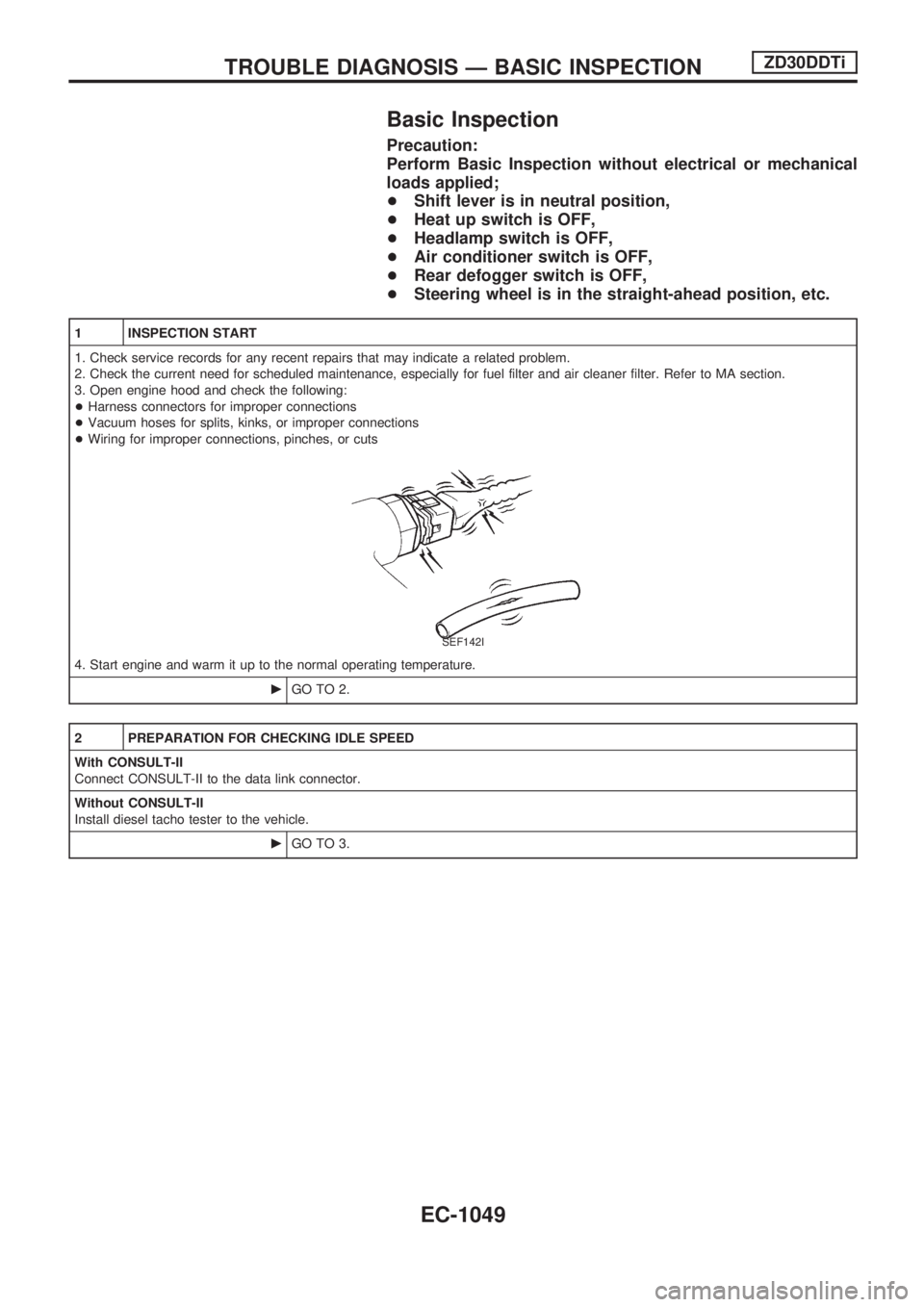
3. Open engine hood and check the following:
+Harness connectors for improper connections
+Vacuum hoses for splits, kinks, or improper connections
+Wiring for improper connections, pinches, or cuts
SEF142I
4. Start engine and warm it up to the normal operating temperature.
cGO TO 2.
2 PREPARATION FOR CHECKING IDLE SPEED
With CONSULT-II
Connect CONSULT-II to the data link connector.
Without CONSULT-II
Install diesel tacho tester to the vehicle.
cGO TO 3.
TROUBLE DIAGNOSIS Ð BASIC INSPECTIONZD30DDTi
EC-1049
Page 513 of 1033
Supplemental Restraint System (SRS) ªAIR
BAGº and ªSEAT BELT PRE-TENSIONERº
The Supplemental Restraint System such as ªAIR BAGº and ªSEAT BELT PRE-TENSIONERº used along
with a seat belt, helps to reduce the risk or severity of injury to the driver and front passenger for certain
types of collision. The SRS system composition which is available to NISSAN MODEL Y61 is as follows (The
composition varies according to the destination and optional equipment.):
+For a frontal collision
The Supplemental Restraint System consists of driver air bag module (located in the center of the
steering wheel), front passenger air bag module (located on the instrument panel on passenger side),
seat belt pre-tensioners, a diagnosis sensor unit, warning lamp, wiring harness and spiral cable.
+For a side collision
The Supplemental Restraint System consists of front side air bag module (located in the outer side of
front seat), satellite sensor, diagnosis sensor unit (one of components of air bags for a frontal collision),
wiring harness, warning lamp (one of components of air bags for a frontal collision).
Information necessary to service the system safely is included in theRS sectionof this Service Manual.
WARNING:
+To avoid rendering the SRS inoperative, which could increase the risk of personal injury or death
in the event of a collision which would result in air bag inflation, all maintenance should be per-
formed by an authorized NISSAN dealer.
+Improper maintenance, including incorrect removal and installation of the SRS, can lead to per-
sonal injury caused by unintentional activation of the system. For removal of Spiral Cable and
Air Bag Module, see the RS section.
+Do not use electrical test equipment on any circuit related to the SRS unless instructed to in this
Service Manual. Spiral cable and wiring harnesses covered with yellow insulation tape either just
before the harness connectors or for the complete harness are related to the SRS.
PRECAUTIONS AND PREPARATION
EL-1003
Page 847 of 1033
Supplemental Restraint System (SRS) ªAIR
BAGº and ªSEAT BELT PRE-TENSIONERº
The Supplemental Restraint System such as ªAIR BAGº and ªSEAT BELT PRE-TENSIONERº used along
with a seat belt, helps to reduce the risk or severity of injury to the driver and front passenger for certain
types of collision. The SRS system composition which is available to NISSAN MODEL Y61 is as follows (The
composition varies according to the destination and optional equipment.):
+For a frontal collision
The Supplemental Restraint System consists of driver air bag module (located in the center of the
steering wheel), front passenger air bag module (located on the instrument panel on passenger side),
seat belt pre-tensioners, a diagnosis sensor unit, warning lamp, wiring harness and spiral cable.
+For a side collision
The Supplemental Restraint System consists of front side air bag module (located in the outer side of
front seat), satellite sensor, diagnosis sensor unit (one of components of air bags for a frontal collision),
wiring harness, warning lamp (one of components of air bags for a frontal collision).
Information necessary to service the system safely is included in theRS sectionof this Service Manual.
WARNING:
+To avoid rendering the SRS inoperative, which could increase the risk of personal injury or death
in the event of a collision which would result in air bag inflation, all maintenance should be per-
formed by an authorized NISSAN dealer.
+Improper maintenance, including incorrect removal and installation of the SRS, can lead to per-
sonal injury caused by unintentional activation of the system. For removal of Spiral Cable and
Air Bag Module, see the RS section.
+Do not use electrical test equipment on any circuit related to the SRS unless instructed to in this
Service Manual. Spiral cable and wiring harnesses covered with yellow insulation tape either just
before the harness connectors or for the complete harness are related to the SRS.
Precautions for Fuel
DIESEL ENGINE*:
Diesel fuel of at least 50 cetane for ZD30DDTi engine
* If two types of diesel fuel are available, use summer or win-
ter fuel properly according to the following temperature con-
ditions.
+Above þ7ÉC (20ÉF) ... Summer type diesel fuel.
+Below þ7ÉC (20ÉF) ... Winter type diesel fuel.
CAUTION:
+Do not use home heating oil, gasoline, or other alternate
fuels in your diesel engine. The use of those can cause
engine damage.
+Do not use summer fuel at temperature below þ7ÉC
(20ÉF). The cold temperature will cause wax to form in
the fuel. As a result, it may prevent the engine from run-
ning smoothly.
+Do not add gasoline or other alternate fuels to diesel
fuel.
PRECAUTIONS AND PREPARATION
GI-1002
Page 857 of 1033
Supplemental Restraint System (SRS) ªAIR
BAGº and ªSEAT BELT PRE-TENSIONERº
The Supplemental Restraint System such as ªAIR BAGº and ªSEAT BELT PRE-TENSIONERº used along
with a seat belt, helps to reduce the risk or severity of injury to the driver and front passenger for certain
types of collision. The SRS system composition which is available to NISSAN MODEL Y61 is as follows (The
composition varies according to the destination and optional equipment.):
+For a frontal collision
The Supplemental Restraint System consists of driver air bag module (located in the center of the
steering wheel), front passenger air bag module (located on the instrument panel on passenger side),
seat belt pre-tensioners, a diagnosis sensor unit, warning lamp, wiring harness and spiral cable.
+For a side collision
The Supplemental Restraint System consists of front side air bag module (located in the outer side of
front seat), satellite sensor, diagnosis sensor unit (one of components of air bags for a frontal collision),
wiring harness, warning lamp (one of components of air bags for a frontal collision).
Information necessary to service the system safely is included in theRS sectionof this Service Manual.
WARNING:
+To avoid rendering the SRS inoperative, which could increase the risk of personal injury or death
in the event of a collision which would result in air bag inflation, all maintenance should be per-
formed by an authorized NISSAN dealer.
+Improper maintenance, including incorrect removal and installation of the SRS, can lead to per-
sonal injury caused by unintentional activation of the system. For removal of Spiral Cable and
Air Bag Module, see the RS section.
+Do not use electrical test equipment on any circuit related to the SRS unless instructed to in this
Service Manual. Spiral cable and wiring harnesses covered with yellow insulation tape either just
before the harness connectors or for the complete harness are related to the SRS.
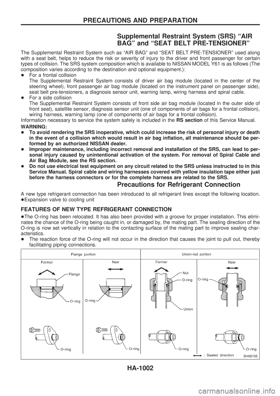
Precautions for Refrigerant Connection
A new type refrigerant connection has been introduced to all refrigerant lines except the following location.
+Expansion valve to cooling unit
FEATURES OF NEW TYPE REFRIGERANT CONNECTION
+The O-ring has been relocated. It has also been provided with a groove for proper installation. This elimi-
nates the chance of the O-ring being caught in, or damaged by, the mating part. The sealing direction of the
O-ring is now set vertically in relation to the contacting surface of the mating part to improve sealing char-
acteristics.
+The reaction force of the O-ring will not occur in the direction that causes the joint to pull out, thereby
facilitating piping connections.
SHA815E
PRECAUTIONS AND PREPARATION
HA-1002
Page 901 of 1033
![NISSAN PATROL 2000 Electronic Repair Manual Chassis and Body Maintenance
Abbreviations: R = Replace, I = Inspect: Correct or replace if necessary, L = Lubricate, T = Tighten, [ ] = At the specified mileage only
MAINTENANCE OPERATIONMAINTENANCE NISSAN PATROL 2000 Electronic Repair Manual Chassis and Body Maintenance
Abbreviations: R = Replace, I = Inspect: Correct or replace if necessary, L = Lubricate, T = Tighten, [ ] = At the specified mileage only
MAINTENANCE OPERATIONMAINTENANCE](/manual-img/5/57367/w960_57367-900.png)
Chassis and Body Maintenance
Abbreviations: R = Replace, I = Inspect: Correct or replace if necessary, L = Lubricate, T = Tighten, [ ] = At the specified mileage only
MAINTENANCE OPERATIONMAINTENANCE INTERVAL
Perform on a kilometer basis, but on an annual basis
when driving less than 15,000 km (9,000 miles) per
year.km x 1,000 15 30 45 60 75 90
(miles x 1,000) (9) (18) (27) (36) (45) (54)
Months 12 24 36 48 60 72
Underhood and under vehicleReference
pages
Headlamp aimingIIIIII Ð
When alignment (if necessary, balance & rotate wheels)IIIIII Ð
Brake pads, rotors & other brake componentsHIIIIII Ð
Foot brake, parking brake & clutch (for free play, stroke & operation)IIIIII Ð
Brake booster vacuum hoses, connections & check valve I I I Ð
Brake & clutch, systems and fluid (for level and leaks)IIIIII Ð
Brake fluidHRRRÐ
Power steering fluid and lines (for level and leaks)IIIIII Ð
Supplemental air bag systems See NOTE (1)RS-1007
Ventilation air filterHRRRÐ
Manual transmission oil (Inspect for leaks. Replace if leaks are found.)IIIII[R] Ð
Automatic transmission fluid (for level and leaks)HIIIIII Ð
Greasing point of propeller shaft See NOTE (2)LLLLLL Ð
Transfer fluid and limited-slip differential (LSD) gear oil (for
level & leaks or replace)HSee NOTE (3) I I I R I I Ð
Drive shafts & steering damperHIIIIII Ð
Front wheel bearing greaseHIRIRIR Ð
Front axle joint in knuckle flangeLLLÐ
Free-running hub greaseHIIIIII Ð
Body mounting bolts & nutsTTTTTT Ð
Steering gear & linkage, axle & suspension parts, propeller shaft & exhaust systemHIIIIII Ð
Body corrosion See NOTE (4)Ð
NOTE: (1) Inspect after 10 years, then every 2 years.
(2) The propeller shaft should be re-greased after being immersed in water.
(3) Including differential gear with differential lock.
(4) Inspect once per year.
HMaintenance items with ªHº should be performed more frequently according to ªMaintenance under severe driv-
ing conditionsº.
PERIODIC MAINTENANCE
MA-1003