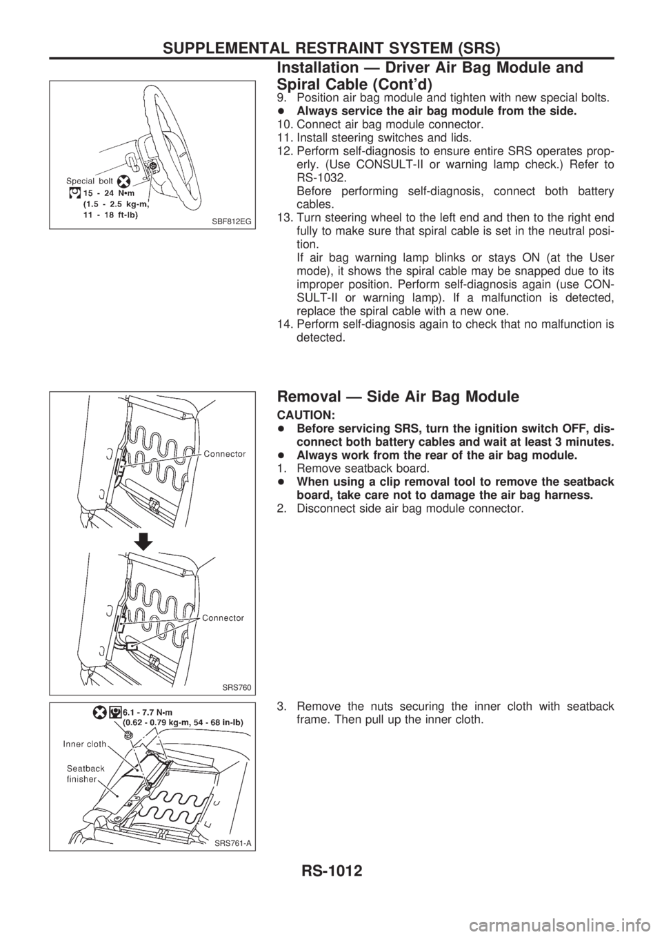
9. Position air bag module and tighten with new special bolts.
+Always service the air bag module from the side.
10. Connect air bag module connector.
11. Install steering switches and lids.
12. Perform self-diagnosis to ensure entire SRS operates prop-
erly. (Use CONSULT-II or warning lamp check.) Refer to
RS-1032.
Before performing self-diagnosis, connect both battery
cables.
13. Turn steering wheel to the left end and then to the right end
fully to make sure that spiral cable is set in the neutral posi-
tion.
If air bag warning lamp blinks or stays ON (at the User
mode), it shows the spiral cable may be snapped due to its
improper position. Perform self-diagnosis again (use CON-
SULT-II or warning lamp). If a malfunction is detected,
replace the spiral cable with a new one.
14. Perform self-diagnosis again to check that no malfunction is
detected.
Removal Ð Side Air Bag Module
CAUTION:
+Before servicing SRS, turn the ignition switch OFF, dis-
connect both battery cables and wait at least 3 minutes.
+Always work from the rear of the air bag module.
1. Remove seatback board.
+When using a clip removal tool to remove the seatback
board, take care not to damage the air bag harness.
2. Disconnect side air bag module connector.
3. Remove the nuts securing the inner cloth with seatback
frame. Then pull up the inner cloth.
SBF812EG
SRS760
SRS761-A
SUPPLEMENTAL RESTRAINT SYSTEM (SRS)
Installation Ð Driver Air Bag Module and
Spiral Cable (Cont'd)
RS-1012
FOR FRONTAL COLLISION
To repair the SRS for a frontal collision, perform the following steps.
When SRS (except the side air bag) is activated in a collision:
V1Replace the diagnosis sensor unit.
V2Remove the air bag modules (except the side air bag module) and seat belt pre-tensioner assemblies.
V3Check the SRS components using the table shown below:
+Replace any SRS components showing visible signs of damage (dents, cracks, deformation).
V4Install new air bag modules (except the side air bag module) and seat belt pre-tensioner assemblies.
V5Conduct self-diagnosis using CONSULT-II, and ªAIR BAGº and ªSEAT BELTº warning lamps (Models
except for Europe). Refer to ªSelf-diagnosisº for details (RS-1032). Ensure entire SRS operates prop-
erly.
When SRS is not activated in a collision:
V1Check the SRS components using the table shown below:
+Replace any SRS components showing visible signs of damage (dents, cracks, deformation).
V2Conduct self-diagnosis using CONSULT-II, and ªAIR BAGº and ªSEAT BELTº warning lamps (Models
except for Europe). Refer to ªSelf-diagnosisº for details (RS-1032). Ensure entire SRS operates prop-
erly.
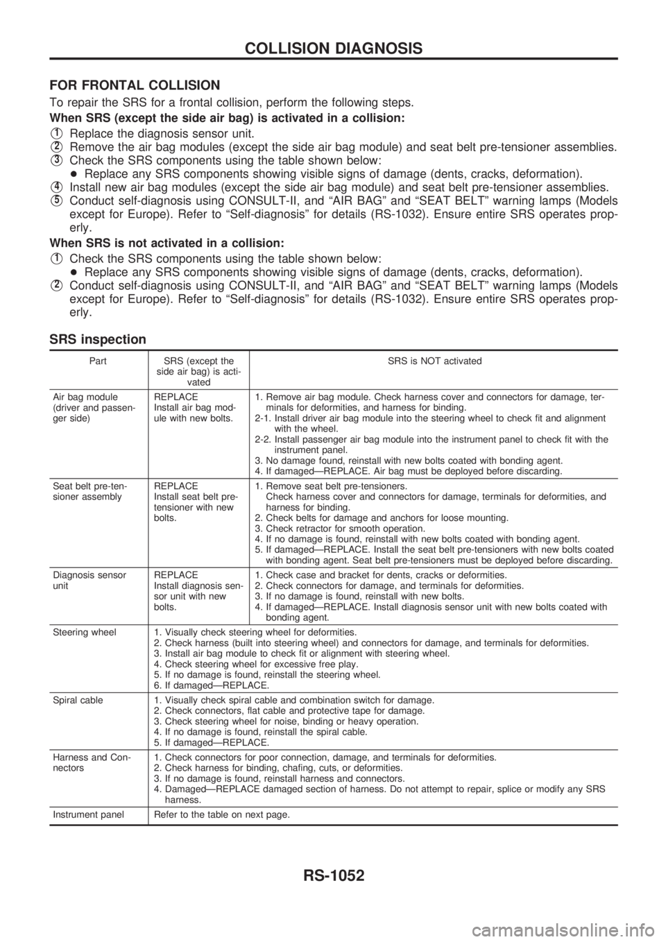
SRS inspection
Part SRS (except the
side air bag) is acti-
vatedSRS is NOT activated
Air bag module
(driver and passen-
ger side)REPLACE
Install air bag mod-
ule with new bolts.1. Remove air bag module. Check harness cover and connectors for damage, ter-
minals for deformities, and harness for binding.
2-1. Install driver air bag module into the steering wheel to check fit and alignment
with the wheel.
2-2. Install passenger air bag module into the instrument panel to check fit with the
instrument panel.
3. No damage found, reinstall with new bolts coated with bonding agent.
4. If damagedÐREPLACE. Air bag must be deployed before discarding.
Seat belt pre-ten-
sioner assemblyREPLACE
Install seat belt pre-
tensioner with new
bolts.1. Remove seat belt pre-tensioners.
Check harness cover and connectors for damage, terminals for deformities, and
harness for binding.
2. Check belts for damage and anchors for loose mounting.
3. Check retractor for smooth operation.
4. If no damage is found, reinstall with new bolts coated with bonding agent.
5. If damagedÐREPLACE. Install the seat belt pre-tensioners with new bolts coated
with bonding agent. Seat belt pre-tensioners must be deployed before discarding.
Diagnosis sensor
unitREPLACE
Install diagnosis sen-
sor unit with new
bolts.1. Check case and bracket for dents, cracks or deformities.
2. Check connectors for damage, and terminals for deformities.
3. If no damage is found, reinstall with new bolts.
4. If damagedÐREPLACE. Install diagnosis sensor unit with new bolts coated with
bonding agent.
Steering wheel 1. Visually check steering wheel for deformities.
2. Check harness (built into steering wheel) and connectors for damage, and terminals for deformities.
3. Install air bag module to check fit or alignment with steering wheel.
4. Check steering wheel for excessive free play.
5. If no damage is found, reinstall the steering wheel.
6. If damagedÐREPLACE.
Spiral cable 1. Visually check spiral cable and combination switch for damage.
2. Check connectors, flat cable and protective tape for damage.
3. Check steering wheel for noise, binding or heavy operation.
4. If no damage is found, reinstall the spiral cable.
5. If damagedÐREPLACE.
Harness and Con-
nectors1. Check connectors for poor connection, damage, and terminals for deformities.
2. Check harness for binding, chafing, cuts, or deformities.
3. If no damage is found, reinstall harness and connectors.
4. DamagedÐREPLACE damaged section of harness. Do not attempt to repair, splice or modify any SRS
harness.
Instrument panel Refer to the table on next page.
COLLISION DIAGNOSIS
RS-1052
Inspection and Adjustment
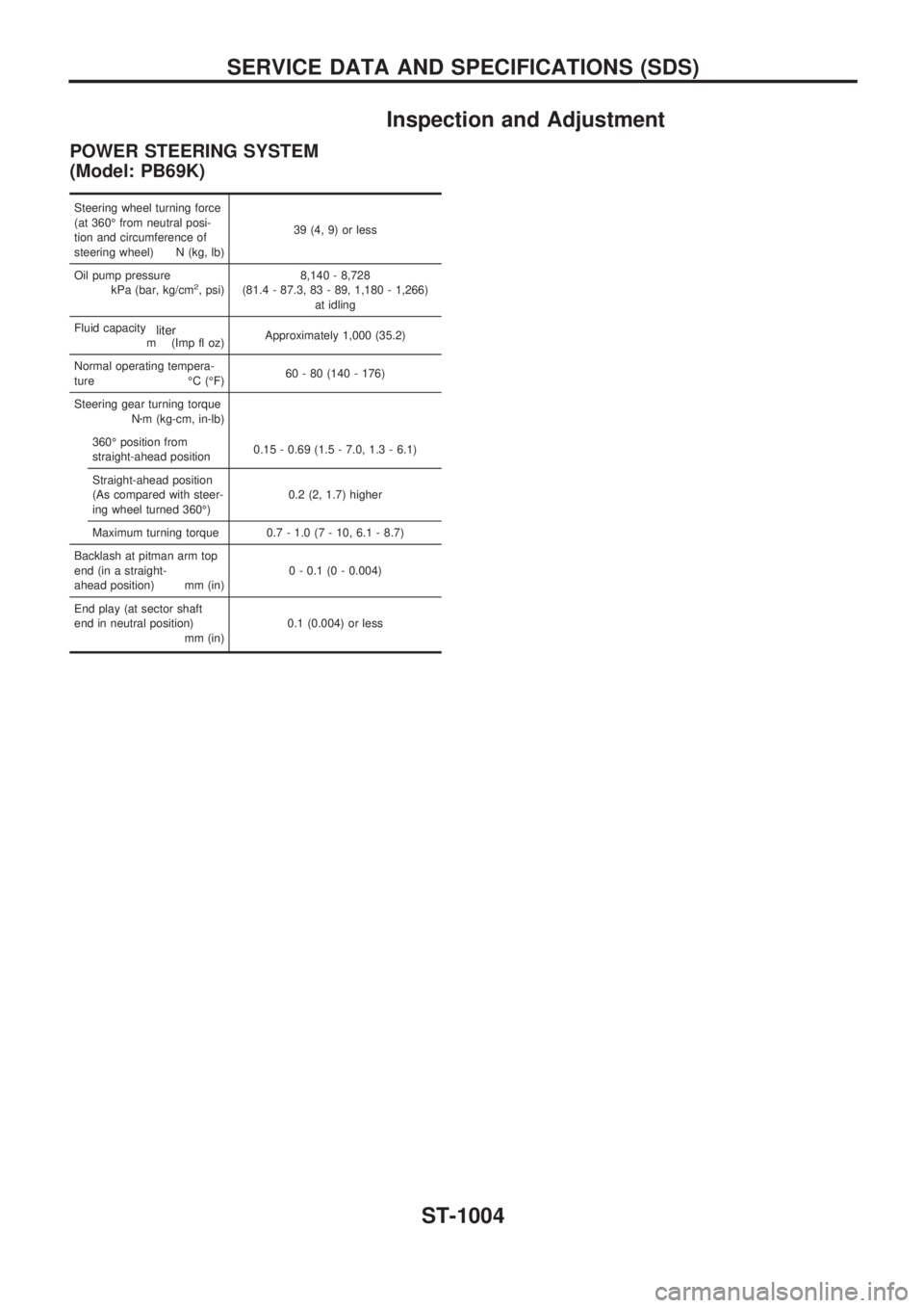
POWER STEERING SYSTEM
(Model: PB69K)
Steering wheel turning force
(at 360É from neutral posi-
tion and circumference of
steering wheel) N (kg, lb)39 (4, 9) or less
Oil pump pressure
kPa (bar, kg/cm
2, psi)8,140 - 8,728
(81.4 - 87.3, 83 - 89, 1,180 - 1,266)
at idling
Fluid capacity
m
liter(Imp fl oz)Approximately 1,000 (35.2)
Normal operating tempera-
ture ÉC (ÉF)60 - 80 (140 - 176)
Steering gear turning torque
Nzm (kg-cm, in-lb)
360É position from
straight-ahead position0.15 - 0.69 (1.5 - 7.0, 1.3 - 6.1)
Straight-ahead position
(As compared with steer-
ing wheel turned 360É)0.2 (2, 1.7) higher
Maximum turning torque 0.7 - 1.0 (7 - 10, 6.1 - 8.7)
Backlash at pitman arm top
end (in a straight-
ahead position) mm (in)0 - 0.1 (0 - 0.004)
End play (at sector shaft
end in neutral position)
mm (in)0.1 (0.004) or less
SERVICE DATA AND SPECIFICATIONS (SDS)
ST-1004