2000 NISSAN PATROL warning light
[x] Cancel search: warning lightPage 98 of 1033
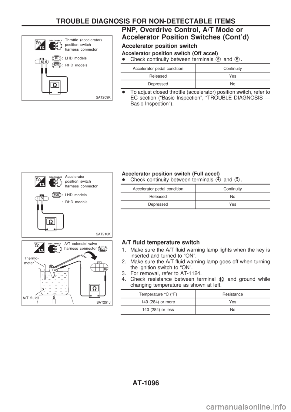
Accelerator position switch
Accelerator position switch (Off accel)
+Check continuity between terminals
V5andV6.
Accelerator pedal condition Continuity
Released Yes
Depressed No
+To adjust closed throttle (accelerator) position switch, refer to
EC section (ªBasic Inspectionº, ªTROUBLE DIAGNOSIS Ð
Basic Inspectionº).
Accelerator position switch (Full accel)
+Check continuity between terminals
V4andV5.
Accelerator pedal condition Continuity
Released No
Depressed Yes
A/T fluid temperature switch
1. Make sure the A/T fluid warning lamp lights when the key is
inserted and turned to ªONº.
2. Make sure the A/T fluid warning lamp goes off when turning
the ignition switch to ªONº.
3. For removal, refer to AT-1124.
4. Check resistance between terminal
V10and ground while
changing temperature as shown at left.
Temperature ÉC (ÉF) Resistance
140 (284) or more Yes
140 (284) or less No
SAT209K
SAT210K
SAT251J
TROUBLE DIAGNOSIS FOR NON-DETECTABLE ITEMS
PNP, Overdrive Control, A/T Mode or
Accelerator Position Switches (Cont'd)
AT-1096
Page 220 of 1033
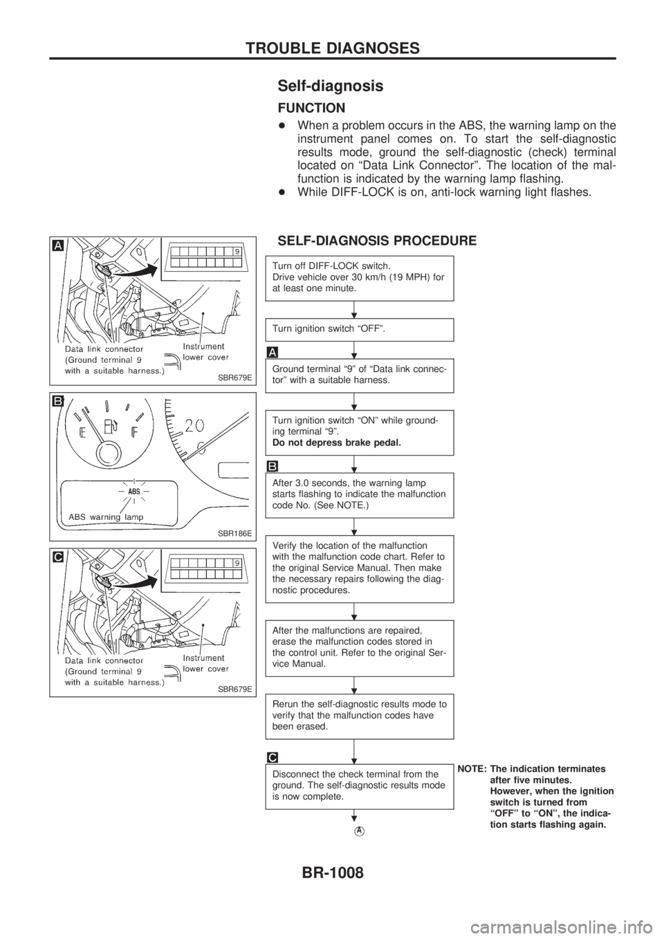
Self-diagnosis
FUNCTION
+When a problem occurs in the ABS, the warning lamp on the
instrument panel comes on. To start the self-diagnostic
results mode, ground the self-diagnostic (check) terminal
located on ªData Link Connectorº. The location of the mal-
function is indicated by the warning lamp flashing.
+While DIFF-LOCK is on, anti-lock warning light flashes.
SELF-DIAGNOSIS PROCEDURE
Turn off DIFF-LOCK switch.
Drive vehicle over 30 km/h (19 MPH) for
at least one minute.
Turn ignition switch ªOFFº.
Ground terminal ª9º of ªData link connec-
torº with a suitable harness.
Turn ignition switch ªONº while ground-
ing terminal ª9º.
Do not depress brake pedal.
After 3.0 seconds, the warning lamp
starts flashing to indicate the malfunction
code No. (See NOTE.)
Verify the location of the malfunction
with the malfunction code chart. Refer to
the original Service Manual. Then make
the necessary repairs following the diag-
nostic procedures.
After the malfunctions are repaired,
erase the malfunction codes stored in
the control unit. Refer to the original Ser-
vice Manual.
Rerun the self-diagnostic results mode to
verify that the malfunction codes have
been erased.
Disconnect the check terminal from the
ground. The self-diagnostic results mode
is now complete.NOTE: The indication terminates
after five minutes.
However, when the ignition
switch is turned from
ªOFFº to ªONº, the indica-
tion starts flashing again.
VA
SBR679E
SBR186E
SBR679E
.
.
.
.
.
.
.
.
.
TROUBLE DIAGNOSES
BR-1008
Page 266 of 1033
2. Change the diagnostic test mode from Mode II to Mode I by using the data link connector. (See
EC-1035.)
The emission related diagnostic information in the ECM can be erased by changing the diagnostic test mode.
+If the battery is disconnected, the emission-related diagnostic information will be lost after
approx. 24 hours.
+Erasing the emission-related diagnostic information using CONSULT-II is easier and quicker than
switching the diagnostic test mode using the data link connector.
NATS (Nissan Anti-Theft System)
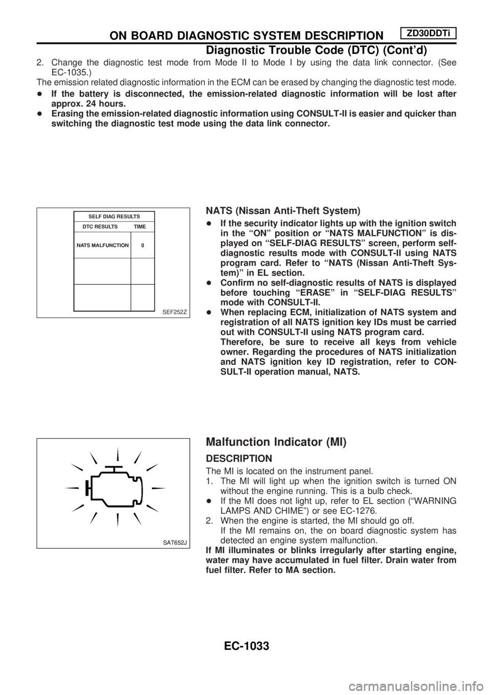
+If the security indicator lights up with the ignition switch
in the ªONº position or ªNATS MALFUNCTIONº is dis-
played on ªSELF-DIAG RESULTSº screen, perform self-
diagnostic results mode with CONSULT-II using NATS
program card. Refer to ªNATS (Nissan Anti-Theft Sys-
tem)º in EL section.
+Confirm no self-diagnostic results of NATS is displayed
before touching ªERASEº in ªSELF-DIAG RESULTSº
mode with CONSULT-II.
+When replacing ECM, initialization of NATS system and
registration of all NATS ignition key IDs must be carried
out with CONSULT-II using NATS program card.
Therefore, be sure to receive all keys from vehicle
owner. Regarding the procedures of NATS initialization
and NATS ignition key ID registration, refer to CON-
SULT-II operation manual, NATS.
Malfunction Indicator (MI)
DESCRIPTION
The MI is located on the instrument panel.
1. The MI will light up when the ignition switch is turned ON
without the engine running. This is a bulb check.
+If the MI does not light up, refer to EL section (ªWARNING
LAMPS AND CHIMEº) or see EC-1276.
2. When the engine is started, the MI should go off.
If the MI remains on, the on board diagnostic system has
detected an engine system malfunction.
If MI illuminates or blinks irregularly after starting engine,
water may have accumulated in fuel filter. Drain water from
fuel filter. Refer to MA section.
SEF252Z
SAT652J
ON BOARD DIAGNOSTIC SYSTEM DESCRIPTIONZD30DDTi
Diagnostic Trouble Code (DTC) (Cont'd)
EC-1033
Page 267 of 1033
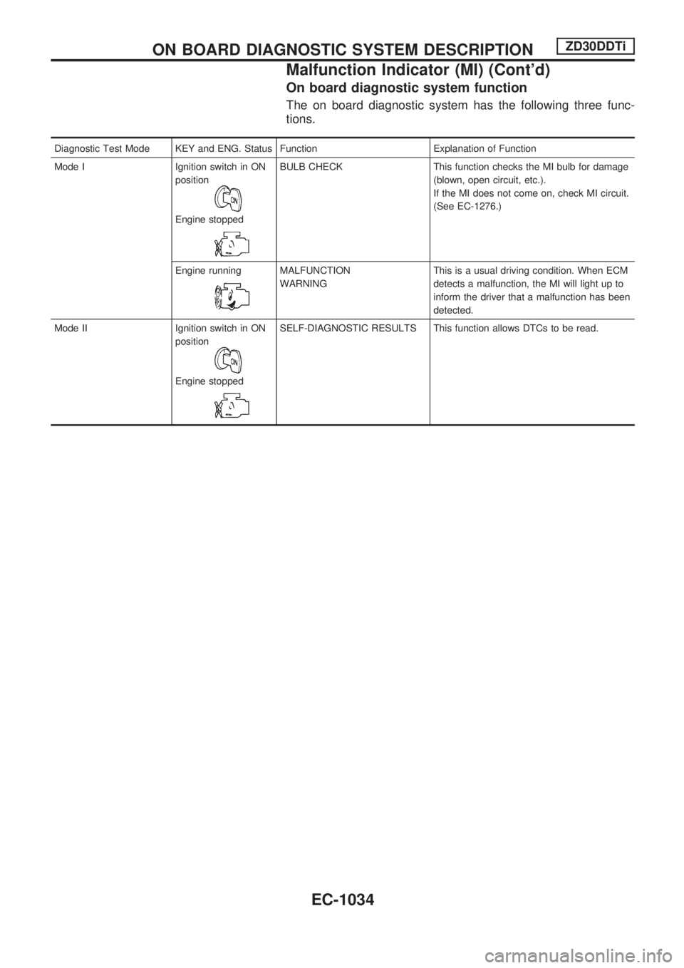
On board diagnostic system function
The on board diagnostic system has the following three func-
tions.
Diagnostic Test Mode KEY and ENG. Status Function Explanation of Function
Mode I Ignition switch in ON
position
Engine stopped
BULB CHECK This function checks the MI bulb for damage
(blown, open circuit, etc.).
If the MI does not come on, check MI circuit.
(See EC-1276.)
Engine running
MALFUNCTION
WARNINGThis is a usual driving condition. When ECM
detects a malfunction, the MI will light up to
inform the driver that a malfunction has been
detected.
Mode II Ignition switch in ON
position
Engine stopped
SELF-DIAGNOSTIC RESULTS This function allows DTCs to be read.
ON BOARD DIAGNOSTIC SYSTEM DESCRIPTIONZD30DDTi
Malfunction Indicator (MI) (Cont'd)
EC-1034
Page 601 of 1033
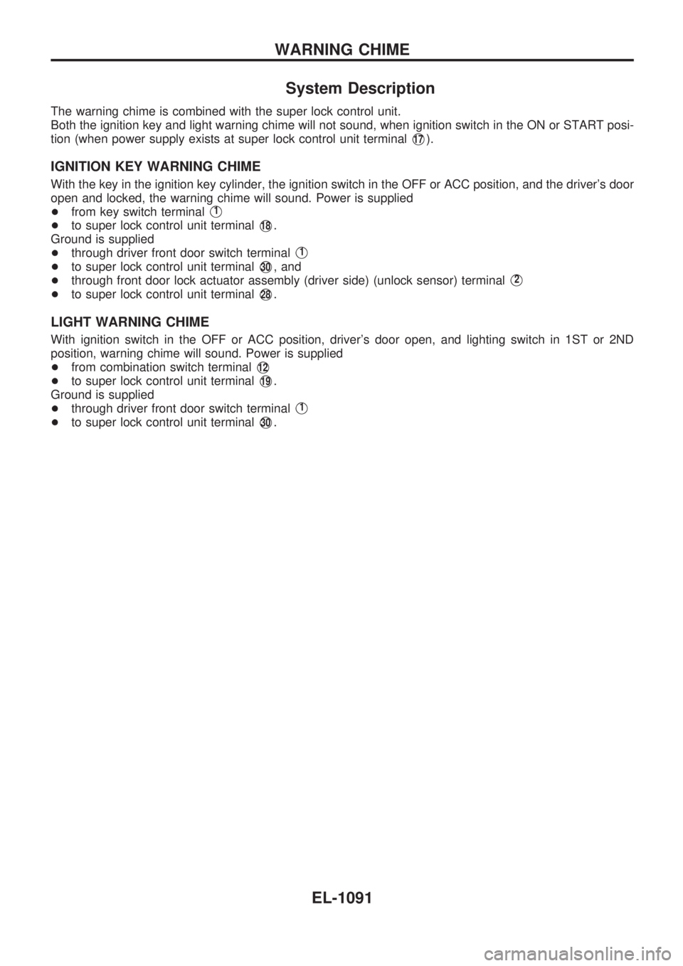
System Description
The warning chime is combined with the super lock control unit.
Both the ignition key and light warning chime will not sound, when ignition switch in the ON or START posi-
tion (when power supply exists at super lock control unit terminal
V17).
IGNITION KEY WARNING CHIME
With the key in the ignition key cylinder, the ignition switch in the OFF or ACC position, and the driver's door
open and locked, the warning chime will sound. Power is supplied
+from key switch terminal
V1
+to super lock control unit terminalV18.
Ground is supplied
+through driver front door switch terminal
V1
+to super lock control unit terminalV30, and
+through front door lock actuator assembly (driver side) (unlock sensor) terminal
V2
+to super lock control unit terminalV28.
LIGHT WARNING CHIME
With ignition switch in the OFF or ACC position, driver's door open, and lighting switch in 1ST or 2ND
position, warning chime will sound. Power is supplied
+from combination switch terminal
V12
+to super lock control unit terminalV19.
Ground is supplied
+through driver front door switch terminal
V1
+to super lock control unit terminalV30.
WARNING CHIME
EL-1091
Page 604 of 1033
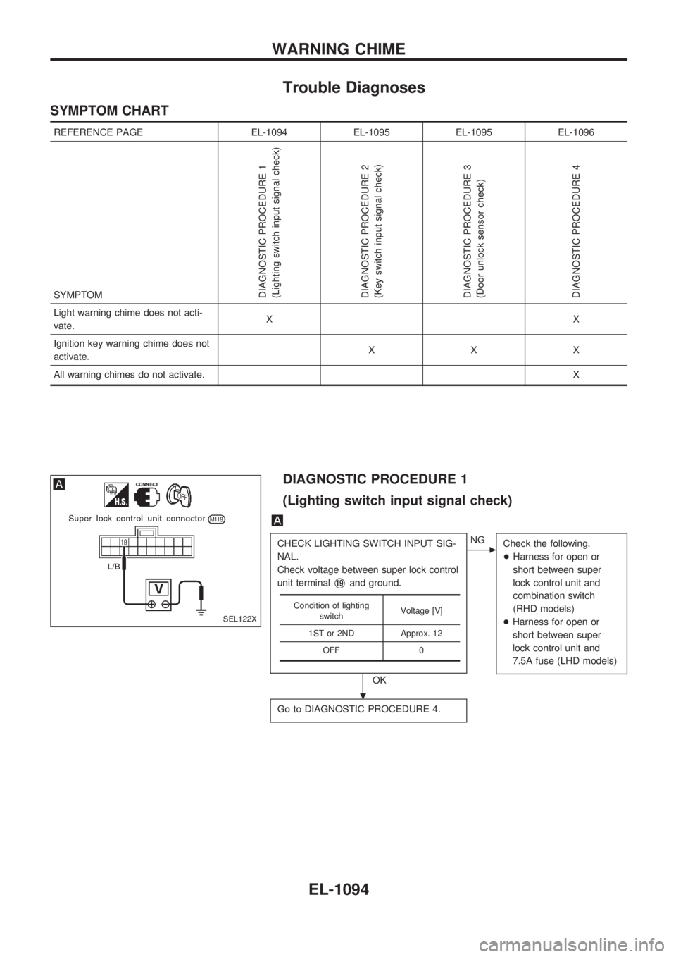
Trouble Diagnoses
SYMPTOM CHART
REFERENCE PAGE EL-1094 EL-1095 EL-1095 EL-1096
SYMPTOM
DIAGNOSTIC PROCEDURE 1
(Lighting switch input signal check)
DIAGNOSTIC PROCEDURE 2
(Key switch input signal check)
DIAGNOSTIC PROCEDURE 3
(Door unlock sensor check)
DIAGNOSTIC PROCEDURE 4
Light warning chime does not acti-
vate.XX
Ignition key warning chime does not
activate.XXX
All warning chimes do not activate.X
DIAGNOSTIC PROCEDURE 1
(Lighting switch input signal check)
CHECK LIGHTING SWITCH INPUT SIG-
NAL.
Check voltage between super lock control
unit terminal
V19and ground.
OK
cNG
Check the following.
+Harness for open or
short between super
lock control unit and
combination switch
(RHD models)
+Harness for open or
short between super
lock control unit and
7.5A fuse (LHD models)
Go to DIAGNOSTIC PROCEDURE 4.
Condition of lighting
switchVoltage [V]
1ST or 2ND Approx. 12
OFF 0
SEL122X
.
WARNING CHIME
EL-1094
Page 669 of 1033
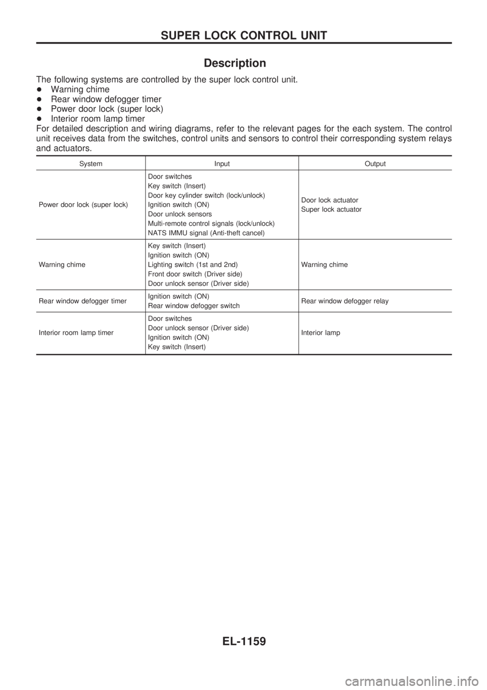
Description
The following systems are controlled by the super lock control unit.
+Warning chime
+Rear window defogger timer
+Power door lock (super lock)
+Interior room lamp timer
For detailed description and wiring diagrams, refer to the relevant pages for the each system. The control
unit receives data from the switches, control units and sensors to control their corresponding system relays
and actuators.
System Input Output
Power door lock (super lock)Door switches
Key switch (Insert)
Door key cylinder switch (lock/unlock)
Ignition switch (ON)
Door unlock sensors
Multi-remote control signals (lock/unlock)
NATS IMMU signal (Anti-theft cancel)Door lock actuator
Super lock actuator
Warning chimeKey switch (Insert)
Ignition switch (ON)
Lighting switch (1st and 2nd)
Front door switch (Driver side)
Door unlock sensor (Driver side)Warning chime
Rear window defogger timerIgnition switch (ON)
Rear window defogger switchRear window defogger relay
Interior room lamp timerDoor switches
Door unlock sensor (Driver side)
Ignition switch (ON)
Key switch (Insert)Interior lamp
SUPER LOCK CONTROL UNIT
EL-1159
Page 737 of 1033
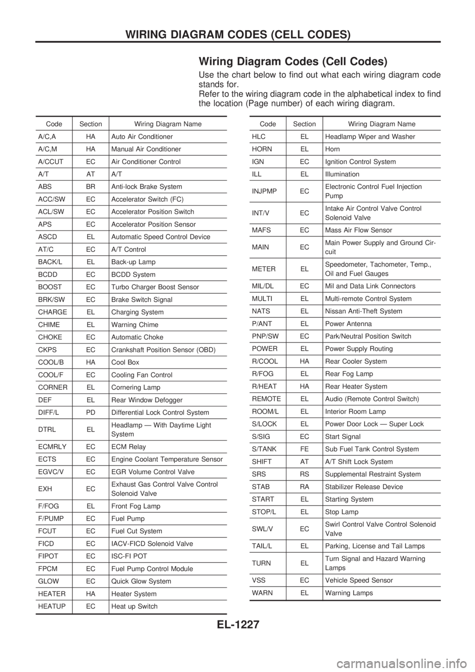
Wiring Diagram Codes (Cell Codes)
Use the chart below to find out what each wiring diagram code
stands for.
Refer to the wiring diagram code in the alphabetical index to find
the location (Page number) of each wiring diagram.
Code Section Wiring Diagram Name
A/C,A HA Auto Air Conditioner
A/C,M HA Manual Air Conditioner
A/CCUT EC Air Conditioner Control
A/T AT A/T
ABS BR Anti-lock Brake System
ACC/SW EC Accelerator Switch (FC)
ACL/SW EC Accelerator Position Switch
APS EC Accelerator Position Sensor
ASCD EL Automatic Speed Control Device
AT/C EC A/T Control
BACK/L EL Back-up Lamp
BCDD EC BCDD System
BOOST EC Turbo Charger Boost Sensor
BRK/SW EC Brake Switch Signal
CHARGE EL Charging System
CHIME EL Warning Chime
CHOKE EC Automatic Choke
CKPS EC Crankshaft Position Sensor (OBD)
COOL/B HA Cool Box
COOL/F EC Cooling Fan Control
CORNER EL Cornering Lamp
DEF EL Rear Window Defogger
DIFF/L PD Differential Lock Control System
DTRL ELHeadlamp Ð With Daytime Light
System
ECMRLY EC ECM Relay
ECTS EC Engine Coolant Temperature Sensor
EGVC/V EC EGR Volume Control Valve
EXH ECExhaust Gas Control Valve Control
Solenoid Valve
F/FOG EL Front Fog Lamp
F/PUMP EC Fuel Pump
FCUT EC Fuel Cut System
FICD EC IACV-FICD Solenoid Valve
FIPOT EC ISC-FI POT
FPCM EC Fuel Pump Control Module
GLOW EC Quick Glow System
HEATER HA Heater System
HEATUP EC Heat up SwitchCode Section Wiring Diagram Name
HLC EL Headlamp Wiper and Washer
HORN EL Horn
IGN EC Ignition Control System
ILL EL Illumination
INJPMP ECElectronic Control Fuel Injection
Pump
INT/V ECIntake Air Control Valve Control
Solenoid Valve
MAFS EC Mass Air Flow Sensor
MAIN ECMain Power Supply and Ground Cir-
cuit
METER ELSpeedometer, Tachometer, Temp.,
Oil and Fuel Gauges
MIL/DL EC Mil and Data Link Connectors
MULTI EL Multi-remote Control System
NATS EL Nissan Anti-Theft System
P/ANT EL Power Antenna
PNP/SW EC Park/Neutral Position Switch
POWER EL Power Supply Routing
R/COOL HA Rear Cooler System
R/FOG EL Rear Fog Lamp
R/HEAT HA Rear Heater System
REMOTE EL Audio (Remote Control Switch)
ROOM/L EL Interior Room Lamp
S/LOCK EL Power Door Lock Ð Super Lock
S/SIG EC Start Signal
S/TANK FE Sub Fuel Tank Control System
SHIFT AT A/T Shift Lock System
SRS RS Supplemental Restraint System
STAB RA Stabilizer Release Device
START EL Starting System
STOP/L EL Stop Lamp
SWL/V ECSwirl Control Valve Control Solenoid
Valve
TAIL/L EL Parking, License and Tail Lamps
TURN ELTurn Signal and Hazard Warning
Lamps
VSS EC Vehicle Speed Sensor
WARN EL Warning Lamps
WIRING DIAGRAM CODES (CELL CODES)
EL-1227