2000 NISSAN PATROL stop start
[x] Cancel search: stop startPage 26 of 1033
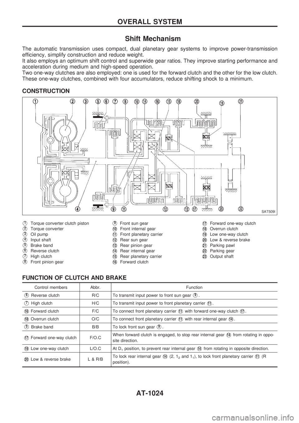
Shift Mechanism
The automatic transmission uses compact, dual planetary gear systems to improve power-transmission
efficiency, simplify construction and reduce weight.
It also employs an optimum shift control and superwide gear ratios. They improve starting performance and
acceleration during medium and high-speed operation.
Two one-way clutches are also employed: one is used for the forward clutch and the other for the low clutch.
These one-way clutches, combined with four accumulators, reduce shifting shock to a minimum.
CONSTRUCTION
V1Torque converter clutch piston
V2Torque converter
V3Oil pump
V4Input shaft
V5Brake band
V6Reverse clutch
V7High clutch
V8Front pinion gear
V9Front sun gear
V10Front internal gear
V11Front planetary carrier
V12Rear sun gear
V13Rear pinion gear
V14Rear internal gear
V15Rear planetary carrier
V16Forward clutch
V17Forward one-way clutch
V18Overrun clutch
V19Low one-way clutch
V20Low & reverse brake
V21Parking pawl
V22Parking gear
V23Output shaft
FUNCTION OF CLUTCH AND BRAKE
Control members Abbr. Function
V6Reverse clutch R/C To transmit input power to front sun gearV9.
V7High clutch H/C To transmit input power to front planetary carrierV11.
V16Forward clutch F/C To connect front planetary carrierV11with forward one-way clutchV17.
V18Overrun clutch O/C To connect front planetary carrierV11with rear internal gearV14.
V5Brake band B/B To lock front sun gearV9.
V17Forward one-way clutch F/O.CWhen forward clutch is engaged, to stop rear internal gearV14from rotating in oppo-
site direction.
V19Low one-way clutch L/O.C At D1position, to prevent rear internal gearV14from rotating in opposite direction.
V20Low & reverse brake L & R/BTo lock rear internal gearV14(2, 12and 11), to lock front planetary carrierV11(R
position).
SAT509I
OVERALL SYSTEM
AT-1024
Page 43 of 1033
A/T Fluid Check
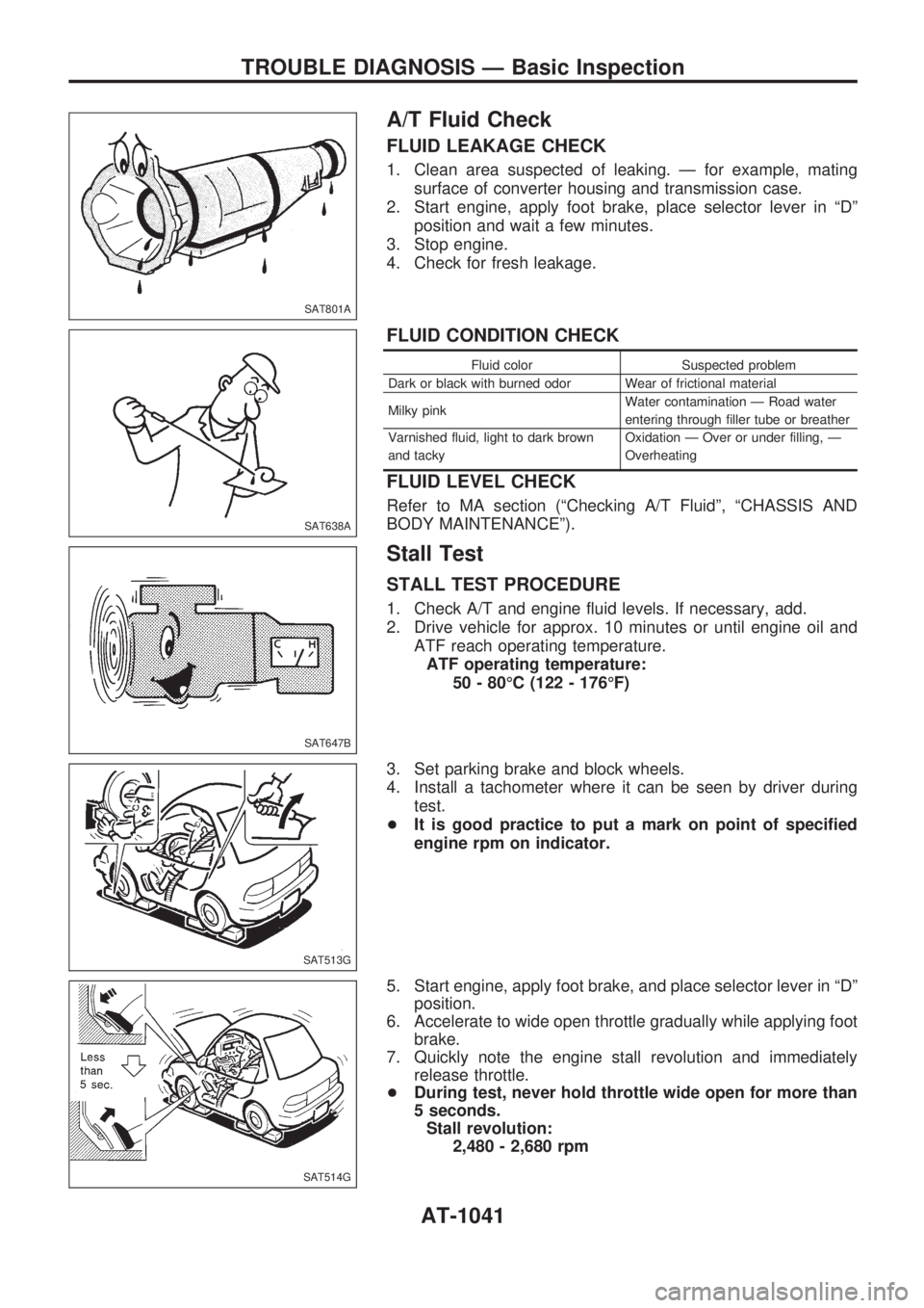
FLUID LEAKAGE CHECK
1. Clean area suspected of leaking. Ð for example, mating
surface of converter housing and transmission case.
2. Start engine, apply foot brake, place selector lever in ªDº
position and wait a few minutes.
3. Stop engine.
4. Check for fresh leakage.
FLUID CONDITION CHECK
Fluid color Suspected problem
Dark or black with burned odor Wear of frictional material
Milky pinkWater contamination Ð Road water
entering through filler tube or breather
Varnished fluid, light to dark brown
and tackyOxidation Ð Over or under filling, Ð
Overheating
FLUID LEVEL CHECK
Refer to MA section (ªChecking A/T Fluidº, ªCHASSIS AND
BODY MAINTENANCEº).
Stall Test
STALL TEST PROCEDURE
1. Check A/T and engine fluid levels. If necessary, add.
2. Drive vehicle for approx. 10 minutes or until engine oil and
ATF reach operating temperature.
ATF operating temperature:
50 - 80ÉC (122 - 176ÉF)
3. Set parking brake and block wheels.
4. Install a tachometer where it can be seen by driver during
test.
+It is good practice to put a mark on point of specified
engine rpm on indicator.
5. Start engine, apply foot brake, and place selector lever in ªDº
position.
6. Accelerate to wide open throttle gradually while applying foot
brake.
7. Quickly note the engine stall revolution and immediately
release throttle.
+During test, never hold throttle wide open for more than
5 seconds.
Stall revolution:
2,480 - 2,680 rpm
SAT801A
SAT638A
SAT647B
SAT513G
SAT514G
TROUBLE DIAGNOSIS Ð Basic Inspection
AT-1041
Page 53 of 1033
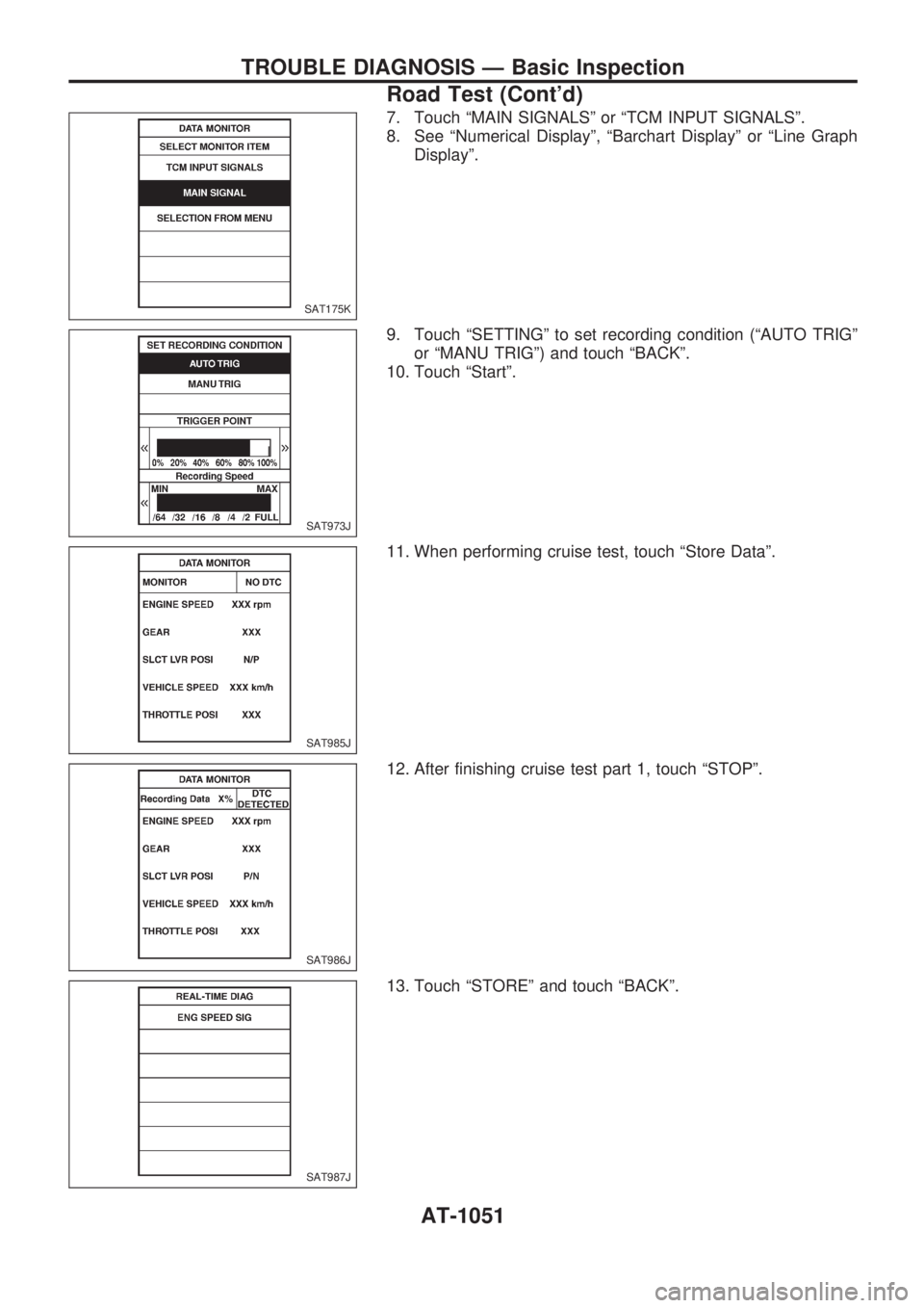
7. Touch ªMAIN SIGNALSº or ªTCM INPUT SIGNALSº.
8. See ªNumerical Displayº, ªBarchart Displayº or ªLine Graph
Displayº.
9. Touch ªSETTINGº to set recording condition (ªAUTO TRIGº
or ªMANU TRIGº) and touch ªBACKº.
10. Touch ªStartº.
11. When performing cruise test, touch ªStore Dataº.
12. After finishing cruise test part 1, touch ªSTOPº.
13. Touch ªSTOREº and touch ªBACKº.
SAT175K
SAT973J
SAT985J
SAT986J
SAT987J
TROUBLE DIAGNOSIS Ð Basic Inspection
Road Test (Cont'd)
AT-1051
Page 57 of 1033
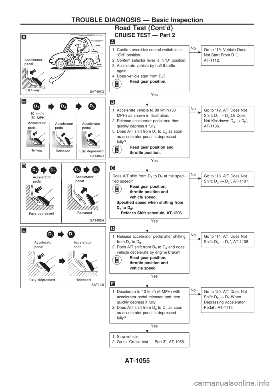
CRUISE TEST Ð Part 2
1. Confirm overdrive control switch is in
ªONº position.
2. Confirm selector lever is in ªDº position.
3. Accelerate vehicle by half throttle
again.
4. Does vehicle start from D
1?
Read gear position.
Yes
cNo
Go to ª19. Vehicle Does
Not Start From D
1º,
AT-1112.
1. Accelerate vehicle to 80 km/h (50
MPH) as shown in illustration.
2. Release accelerator pedal and then
quickly depress it fully.
3. Does A/T shift from D
4to D2as soon
as accelerator pedal is depressed
fully?
Read gear position and
throttle position.
Yes
cNo
Go to ª12. A/T Does Not
Shift: D
1®D2Or Does
Not Kickdown: D
4®D2º,
AT-1106.
Does A/T shift from D2to D3at the speci-
fied speed?
Read gear position,
throttle position and
vehicle speed.
Specified speed when shifting from
D
2to D3:
Refer to Shift schedule, AT-1206.
Yes
cNo
Go to ª13. A/T Does Not
Shift: D
2®D3º, AT-1107.
1. Release accelerator pedal after shifting
from D
2to D3.
2. Does A/T shift from D
3to D4and does
vehicle decelerate by engine brake?
Read gear position,
throttle position and
vehicle speed.
Yes
cNo
Go to ª14. A/T Does Not
Shift: D
3®D4º, AT-1108.
1. Decelerate to 10 km/h (6 MPH) with
accelerator pedal released and then
quickly depress it fully.
2. Does A/T shift from D
2to D1as soon
as accelerator pedal is depressed
fully?
Yes
cNo
Go to ª20. A/T Does Not
Shift: D
2®D1When
Depressing Accelerator
Pedalº, AT-1113.
1. Stop vehicle.
2. Go to ªCruise test Ð Part 3º, AT-1056.
SAT495G
SAT404H
SAT405H
SAT124I
.
.
.
.
.
TROUBLE DIAGNOSIS Ð Basic Inspection
Road Test (Cont'd)
AT-1055
Page 59 of 1033
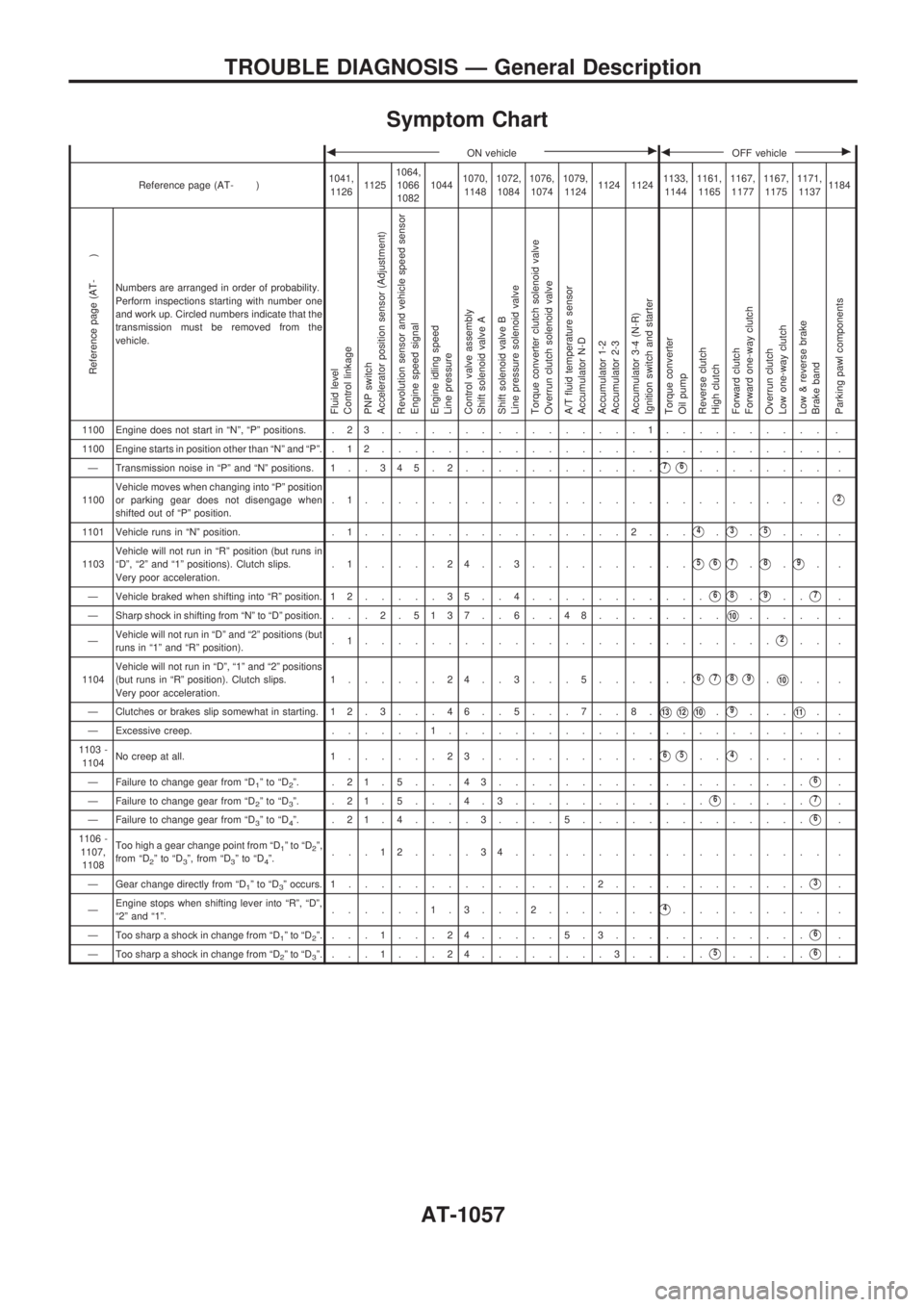
Symptom Chart
bON vehiclecbOFF vehiclec
Reference page (AT- )1041,
112611251064,
1066
108210441070,
11481072,
10841076,
10741079,
11241124 11241133,
11441161,
11651167,
11771167,
11751171,
11371184
Reference page (AT- )
Numbers are arranged in order of probability.
Perform inspections starting with number one
and work up. Circled numbers indicate that the
transmission must be removed from the
vehicle.
Fluid level
Control linkage
PNP switch
Accelerator position sensor (Adjustment)
Revolution sensor and vehicle speed sensor
Engine speed signal
Engine idling speed
Line pressure
Control valve assembly
Shift solenoid valve A
Shift solenoid valve B
Line pressure solenoid valve
Torque converter clutch solenoid valve
Overrun clutch solenoid valve
A/T fluid temperature sensor
Accumulator N-D
Accumulator 1-2
Accumulator 2-3
Accumulator 3-4 (N-R)
Ignition switch and starter
Torque converter
Oil pump
Reverse clutch
High clutch
Forward clutch
Forward one-way clutch
Overrun clutch
Low one-way clutch
Low & reverse brake
Brake band
Parking pawl components
1100 Engine does not start in ªNº, ªPº positions. . 2 3................1.......... .
1100 Engine starts in position other than ªNº and ªPº. . 1 2........................... .
Ð Transmission noise in ªPº and ªNº positions. 1 . . 3 45.2............
V7V6........ .
1100Vehicle moves when changing into ªPº position
or parking gear does not disengage when
shifted out of ªPº position..1............................
V2
1101 Vehicle runs in ªNº position. . 1................2...V4.V3.V5... .
1103Vehicle will not run in ªRº position (but runs in
ªDº, ª2º and ª1º positions). Clutch slips.
Very poor acceleration..1.....24..3..........
V5V6V7.V8.V9..
Ð Vehicle braked when shifting into ªRº position. 1 2.....35..4...........
V6V8.V9..V7.
Ð Sharp shock in shifting from ªNº to ªDº position. . .. 2 . 5137 . . 6 . . 48........
V10..... .
ÐVehicle will not run in ªDº and ª2º positions (but
runs in ª1º and ªRº position)..1.........................
V2.. .
1104Vehicle will not run in ªDº, ª1º and ª2º positions
(but runs in ªRº position). Clutch slips.
Very poor acceleration.1......24..3...5......
V6V7V8V9.V10.. .
Ð Clutches or brakes slip somewhat in starting. 12.3. . .46. .5. . .7. .8.
V13V12V10.V9...V11..
Ð Excessive creep.......1....................... .
1103 -
1104No creep at all. 1......23...........
V6V5..V4..... .
Ð Failure to change gear from ªD
1ºtoªD2º. .21.5...43...................V6.
Ð Failure to change gear from ªD
2ºtoªD3º. .21.5. . .4.3............V6.....V7.
Ð Failure to change gear from ªD
3ºtoªD4º. .21.4....3....5..............V6.
1106 -
1107,
1108Too high a gear change point from ªD
1ºtoªD2º,
from ªD2ºtoªD3º, from ªD3ºtoªD4º....12....34................... .
Ð Gear change directly from ªD
1ºtoªD3º occurs. 1...............2............V3.
ÐEngine stops when shifting lever into ªRº, ªDº,
ª2º and ª1º.......1.3. . .2.......
V4......... .
Ð Too sharp a shock in change from ªD
1ºtoªD2º....1...24.....5.3............V6.
Ð Too sharp a shock in change from ªD
2ºtoªD3º....1...24........3.....V5.....V6.
TROUBLE DIAGNOSIS Ð General Description
AT-1057
Page 61 of 1033
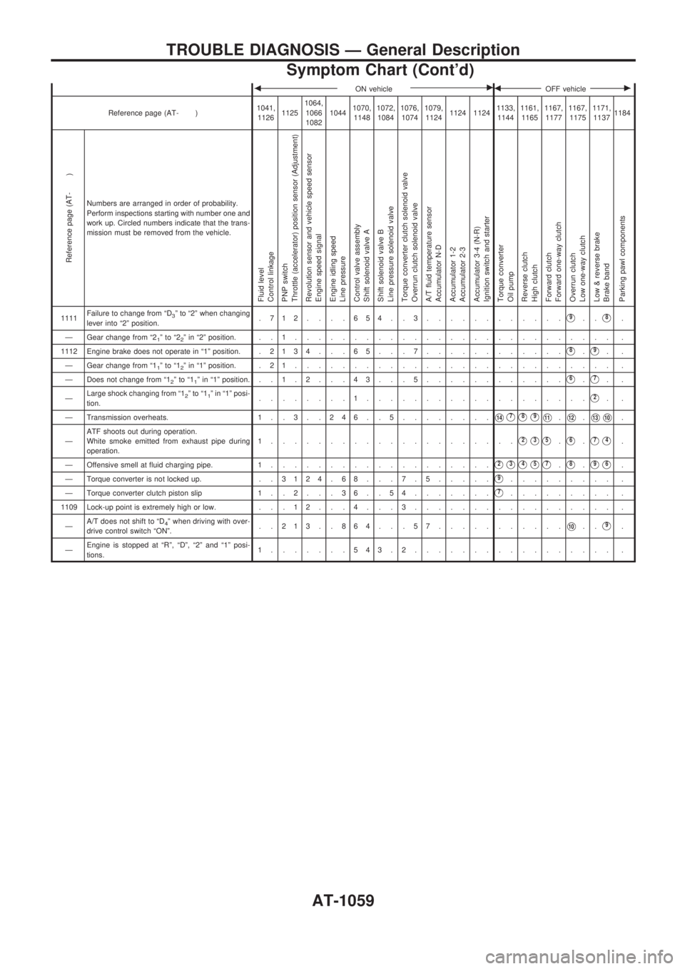
bON vehiclecbOFF vehiclec
Reference page (AT- )1041,
112611251064,
1066
108210441070,
11481072,
10841076,
10741079,
11241124 11241133,
11441161,
11651167,
11771167,
11751171,
11371184
Reference page (AT- )
Numbers are arranged in order of probability.
Perform inspections starting with number one and
work up. Circled numbers indicate that the trans-
mission must be removed from the vehicle.
Fluid level
Control linkage
PNP switch
Throttle (accelerator) position sensor (Adjustment)
Revolution sensor and vehicle speed sensor
Engine speed signal
Engine idling speed
Line pressure
Control valve assembly
Shift solenoid valve A
Shift solenoid valve B
Line pressure solenoid valve
Torque converter clutch solenoid valve
Overrun clutch solenoid valve
A/T fluid temperature sensor
Accumulator N-D
Accumulator 1-2
Accumulator 2-3
Accumulator 3-4 (N-R)
Ignition switch and starter
Torque converter
Oil pump
Reverse clutch
High clutch
Forward clutch
Forward one-way clutch
Overrun clutch
Low one-way clutch
Low & reverse brake
Brake band
Parking pawl components
1111Failure to change from ªD3º to ª2º when changing
lever into ª2º position..712....654..3............V9..V8.
Ð Gear change from ª2
1ºtoª22º in ª2º position. . . 1........................... .
1112 Engine brake does not operate in ª1º position. .2134 . . . 65 . . . 7............
V8.V9..
Ð Gear change from ª1
1ºtoª12º in ª1º position. . 2 1........................... .
Ð Does not change from ª1
2ºtoª11º in ª1º position. ..1.2. . .43. . .5............V6.V7..
ÐLarge shock changing from ª1
2ºtoª11º in ª1º posi-
tion.........1...................V2..
Ð Transmission overheats. 1 . . 3 . . 2 4 6 . . 5........
V14V7V8V9V11.V12.V13V10.
ÐATF shoots out during operation.
White smoke emitted from exhaust pipe during
operation.1.....................
V2V3V5.V6.V7V4.
Ð Offensive smell at fluid charging pipe. 1...................
V2V3V4V5V7.V8.V9V6.
Ð Torque converter is not locked up. . .3124.68. . .7.5.....
V9......... .
Ð Torque converter clutch piston slip 1 . . 2 . . . 3 6 . . 5 4.......
V7......... .
1109 Lock-up point is extremely high or low. . . . 1 2 . . . 4 . . . 3................. .
ÐA/T does not shift to ªD
4º when driving with over-
drive control switch ªONº...213..864...57...........V10..V9.
ÐEngine is stopped at ªRº, ªDº, ª2º and ª1º posi-
tions.1.......543.2................. .
TROUBLE DIAGNOSIS Ð General Description
Symptom Chart (Cont'd)
AT-1059
Page 120 of 1033
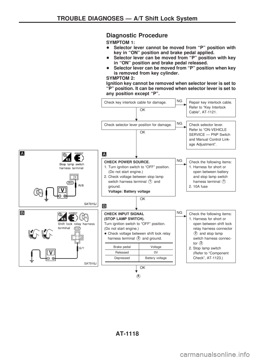
Diagnostic Procedure
SYMPTOM 1:
+Selector lever cannot be moved from ªPº position with
key in ªONº position and brake pedal applied.
+Selector lever can be moved from ªPº position with key
in ªONº position and brake pedal released.
+Selector lever can be moved from ªPº position when key
is removed from key cylinder.
SYMPTOM 2:
Ignition key cannot be removed when selector lever is set to
ªPº position. It can be removed when selector lever is set to
any position except ªPº.
Check key interlock cable for damage.
OK
cNG
Repair key interlock cable.
Refer to ªKey Interlock
Cableº, AT-1121.
Check selector lever position for damage.
OK
cNG
Check selector lever.
Refer to ªON-VEHICLE
SERVICE Ð PNP Switch
and Manual Control Link-
age Adjustmentº.
CHECK POWER SOURCE.
1. Turn ignition switch to ªOFFº position.
(Do not start engine.)
2. Check voltage between stop lamp
switch harness terminal
V1and
ground.
Voltage: Battery voltage
OK
cNG
Check the following items:
1. Harness for short or
open between battery
and stop lamp switch
harness terminal
V1
2. 10A fuse
CHECK INPUT SIGNAL
(STOP LAMP SWITCH).
Turn ignition switch to ªOFFº position.
(Do not start engine.)
+Check voltage between shift lock relay
harness terminal
V2and ground.
OK
cNG
Check the following items:
1. Harness for short or
open between shift lock
relay harness connector
V2and stop lamp
switch harness connec-
tor
V2
2. Stop lamp switch
(Refer to ªComponent
Checkº, AT-1123.)
VA
Brake pedal Voltage
Released 0V
Depressed Battery voltage
SAT915J
SAT916J
.
.
.
.
TROUBLE DIAGNOSES Ð A/T Shift Lock System
AT-1118
Page 272 of 1033
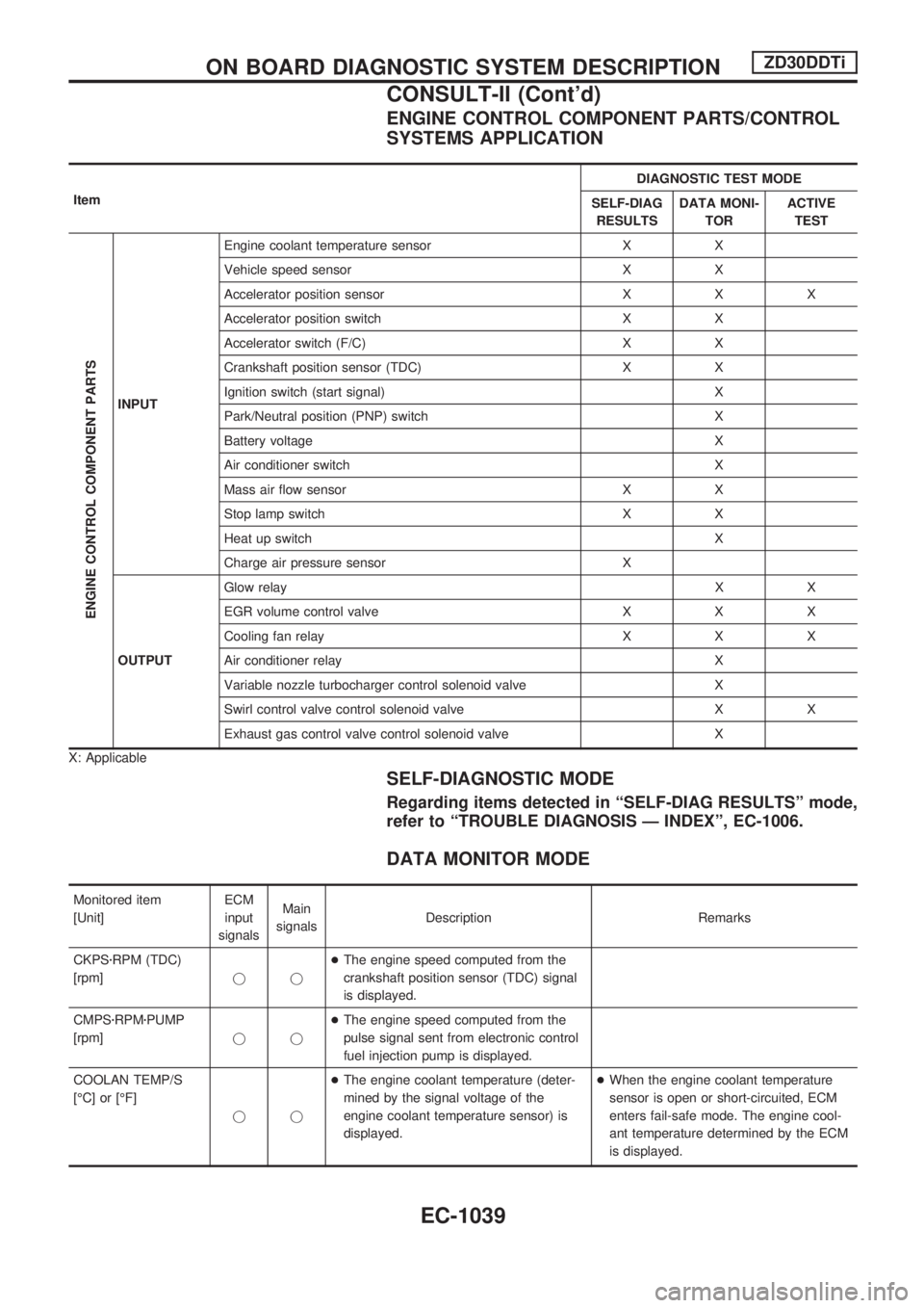
ENGINE CONTROL COMPONENT PARTS/CONTROL
SYSTEMS APPLICATION
ItemDIAGNOSTIC TEST MODE
SELF-DIAG
RESULTSDATA MONI-
TORACTIVE
TEST
ENGINE CONTROL COMPONENT PARTS
INPUTEngine coolant temperature sensor X X
Vehicle speed sensor X X
Accelerator position sensor X X X
Accelerator position switch X X
Accelerator switch (F/C) X X
Crankshaft position sensor (TDC) X X
Ignition switch (start signal) X
Park/Neutral position (PNP) switch X
Battery voltage X
Air conditioner switch X
Mass air flow sensor X X
Stop lamp switch X X
Heat up switch X
Charge air pressure sensor X
OUTPUTGlow relayXX
EGR volume control valve X X X
Cooling fan relay X X X
Air conditioner relay X
Variable nozzle turbocharger control solenoid valve X
Swirl control valve control solenoid valve X X
Exhaust gas control valve control solenoid valve X
X: Applicable
SELF-DIAGNOSTIC MODE
Regarding items detected in ªSELF-DIAG RESULTSº mode,
refer to ªTROUBLE DIAGNOSIS Ð INDEXº, EC-1006.
DATA MONITOR MODE
Monitored item
[Unit]ECM
input
signalsMain
signalsDescription Remarks
CKPSzRPM (TDC)
[rpm]jj+The engine speed computed from the
crankshaft position sensor (TDC) signal
is displayed.
CMPSzRPMzPUMP
[rpm]jj+The engine speed computed from the
pulse signal sent from electronic control
fuel injection pump is displayed.
COOLAN TEMP/S
[ÉC] or [ÉF]
jj+The engine coolant temperature (deter-
mined by the signal voltage of the
engine coolant temperature sensor) is
displayed.+When the engine coolant temperature
sensor is open or short-circuited, ECM
enters fail-safe mode. The engine cool-
ant temperature determined by the ECM
is displayed.
ON BOARD DIAGNOSTIC SYSTEM DESCRIPTIONZD30DDTi
CONSULT-II (Cont'd)
EC-1039