2000 NISSAN PATROL bulb
[x] Cancel search: bulbPage 266 of 1033
2. Change the diagnostic test mode from Mode II to Mode I by using the data link connector. (See
EC-1035.)
The emission related diagnostic information in the ECM can be erased by changing the diagnostic test mode.
+If the battery is disconnected, the emission-related diagnostic information will be lost after
approx. 24 hours.
+Erasing the emission-related diagnostic information using CONSULT-II is easier and quicker than
switching the diagnostic test mode using the data link connector.
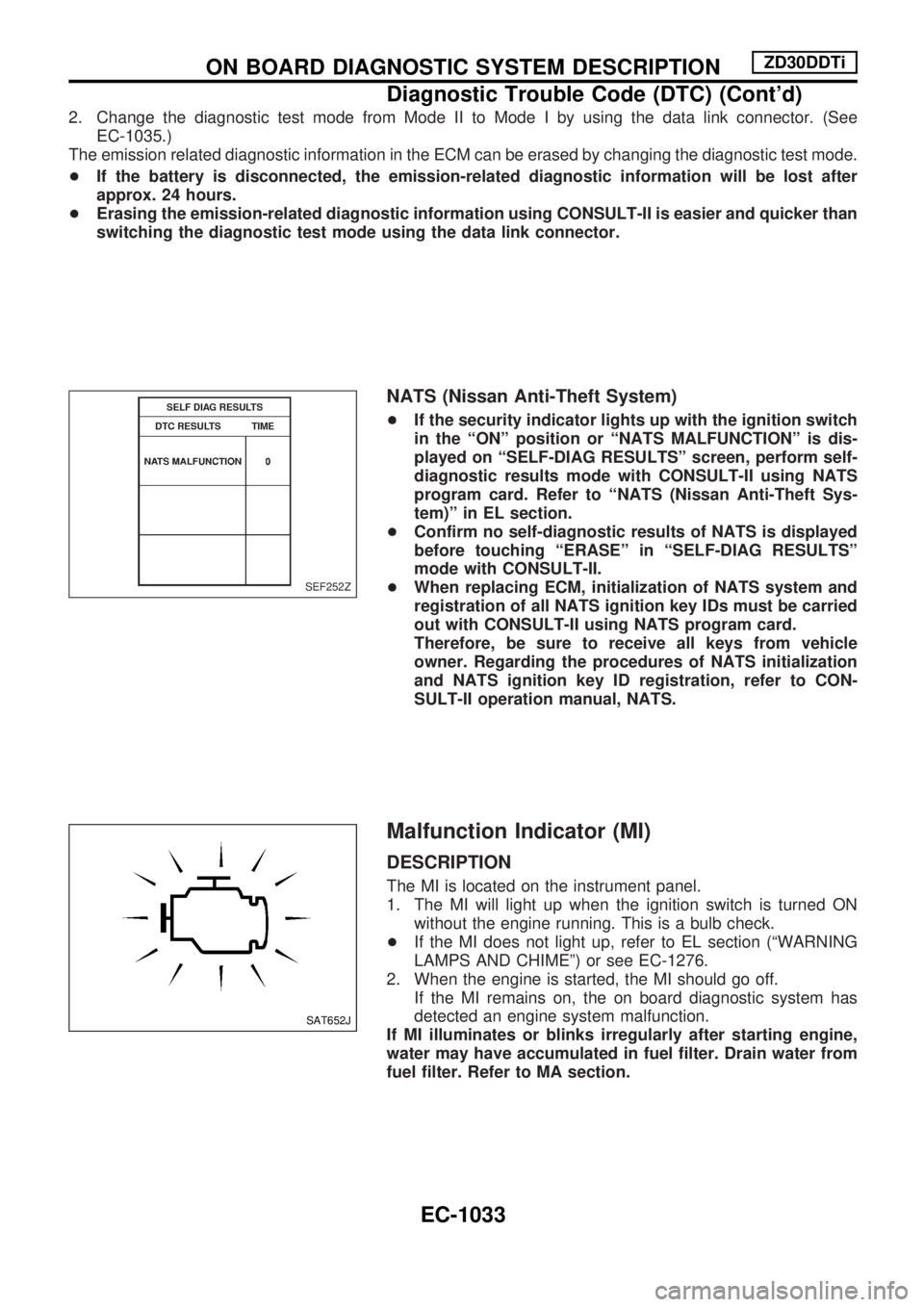
NATS (Nissan Anti-Theft System)
+If the security indicator lights up with the ignition switch
in the ªONº position or ªNATS MALFUNCTIONº is dis-
played on ªSELF-DIAG RESULTSº screen, perform self-
diagnostic results mode with CONSULT-II using NATS
program card. Refer to ªNATS (Nissan Anti-Theft Sys-
tem)º in EL section.
+Confirm no self-diagnostic results of NATS is displayed
before touching ªERASEº in ªSELF-DIAG RESULTSº
mode with CONSULT-II.
+When replacing ECM, initialization of NATS system and
registration of all NATS ignition key IDs must be carried
out with CONSULT-II using NATS program card.
Therefore, be sure to receive all keys from vehicle
owner. Regarding the procedures of NATS initialization
and NATS ignition key ID registration, refer to CON-
SULT-II operation manual, NATS.
Malfunction Indicator (MI)
DESCRIPTION
The MI is located on the instrument panel.
1. The MI will light up when the ignition switch is turned ON
without the engine running. This is a bulb check.
+If the MI does not light up, refer to EL section (ªWARNING
LAMPS AND CHIMEº) or see EC-1276.
2. When the engine is started, the MI should go off.
If the MI remains on, the on board diagnostic system has
detected an engine system malfunction.
If MI illuminates or blinks irregularly after starting engine,
water may have accumulated in fuel filter. Drain water from
fuel filter. Refer to MA section.
SEF252Z
SAT652J
ON BOARD DIAGNOSTIC SYSTEM DESCRIPTIONZD30DDTi
Diagnostic Trouble Code (DTC) (Cont'd)
EC-1033
Page 267 of 1033
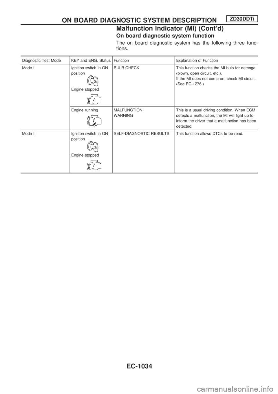
On board diagnostic system function
The on board diagnostic system has the following three func-
tions.
Diagnostic Test Mode KEY and ENG. Status Function Explanation of Function
Mode I Ignition switch in ON
position
Engine stopped
BULB CHECK This function checks the MI bulb for damage
(blown, open circuit, etc.).
If the MI does not come on, check MI circuit.
(See EC-1276.)
Engine running
MALFUNCTION
WARNINGThis is a usual driving condition. When ECM
detects a malfunction, the MI will light up to
inform the driver that a malfunction has been
detected.
Mode II Ignition switch in ON
position
Engine stopped
SELF-DIAGNOSTIC RESULTS This function allows DTCs to be read.
ON BOARD DIAGNOSTIC SYSTEM DESCRIPTIONZD30DDTi
Malfunction Indicator (MI) (Cont'd)
EC-1034
Page 269 of 1033
Diagnostic test mode I Ð Bulb check
In this mode, the MI on the instrument panel should stay ON. If it remains OFF, check the bulb. Refer to EL
section, ªWARNING LAMPS AND CHIMEº or see EC-1276.
Diagnostic test mode I Ð Malfunction warning
MI Condition
ON When the malfunction is detected or the ECM's CPU is malfunctioning.
OFF No malfunction.
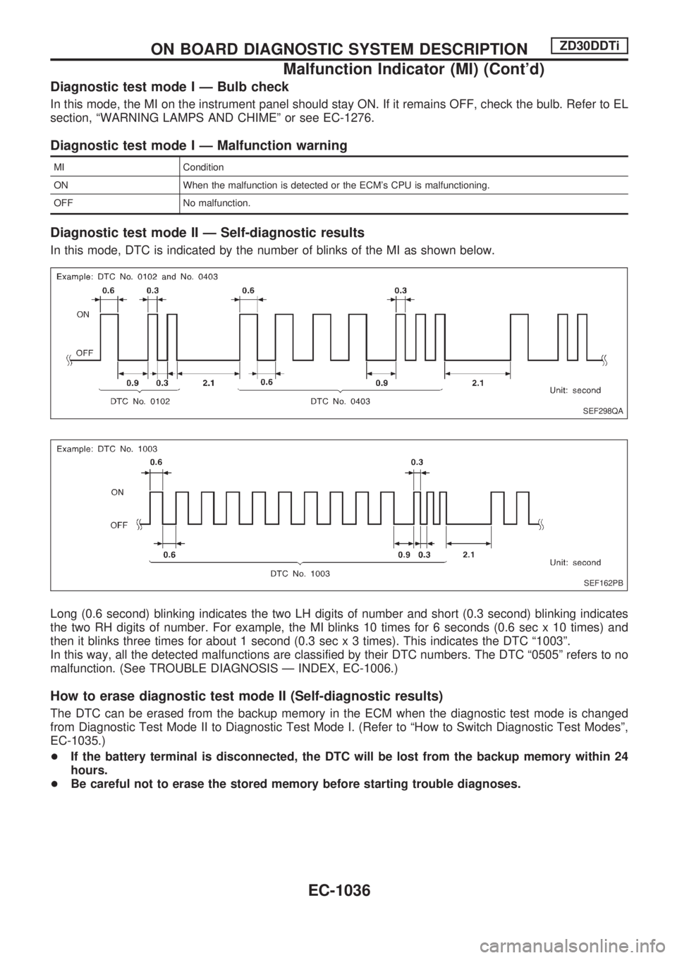
Diagnostic test mode II Ð Self-diagnostic results
In this mode, DTC is indicated by the number of blinks of the MI as shown below.
Long (0.6 second) blinking indicates the two LH digits of number and short (0.3 second) blinking indicates
the two RH digits of number. For example, the MI blinks 10 times for 6 seconds (0.6 sec x 10 times) and
then it blinks three times for about 1 second (0.3 sec x 3 times). This indicates the DTC ª1003º.
In this way, all the detected malfunctions are classified by their DTC numbers. The DTC ª0505º refers to no
malfunction. (See TROUBLE DIAGNOSIS Ð INDEX, EC-1006.)
How to erase diagnostic test mode II (Self-diagnostic results)
The DTC can be erased from the backup memory in the ECM when the diagnostic test mode is changed
from Diagnostic Test Mode II to Diagnostic Test Mode I. (Refer to ªHow to Switch Diagnostic Test Modesº,
EC-1035.)
+If the battery terminal is disconnected, the DTC will be lost from the backup memory within 24
hours.
+Be careful not to erase the stored memory before starting trouble diagnoses.
SEF298QA
SEF162PB
ON BOARD DIAGNOSTIC SYSTEM DESCRIPTIONZD30DDTi
Malfunction Indicator (MI) (Cont'd)
EC-1036
Page 567 of 1033
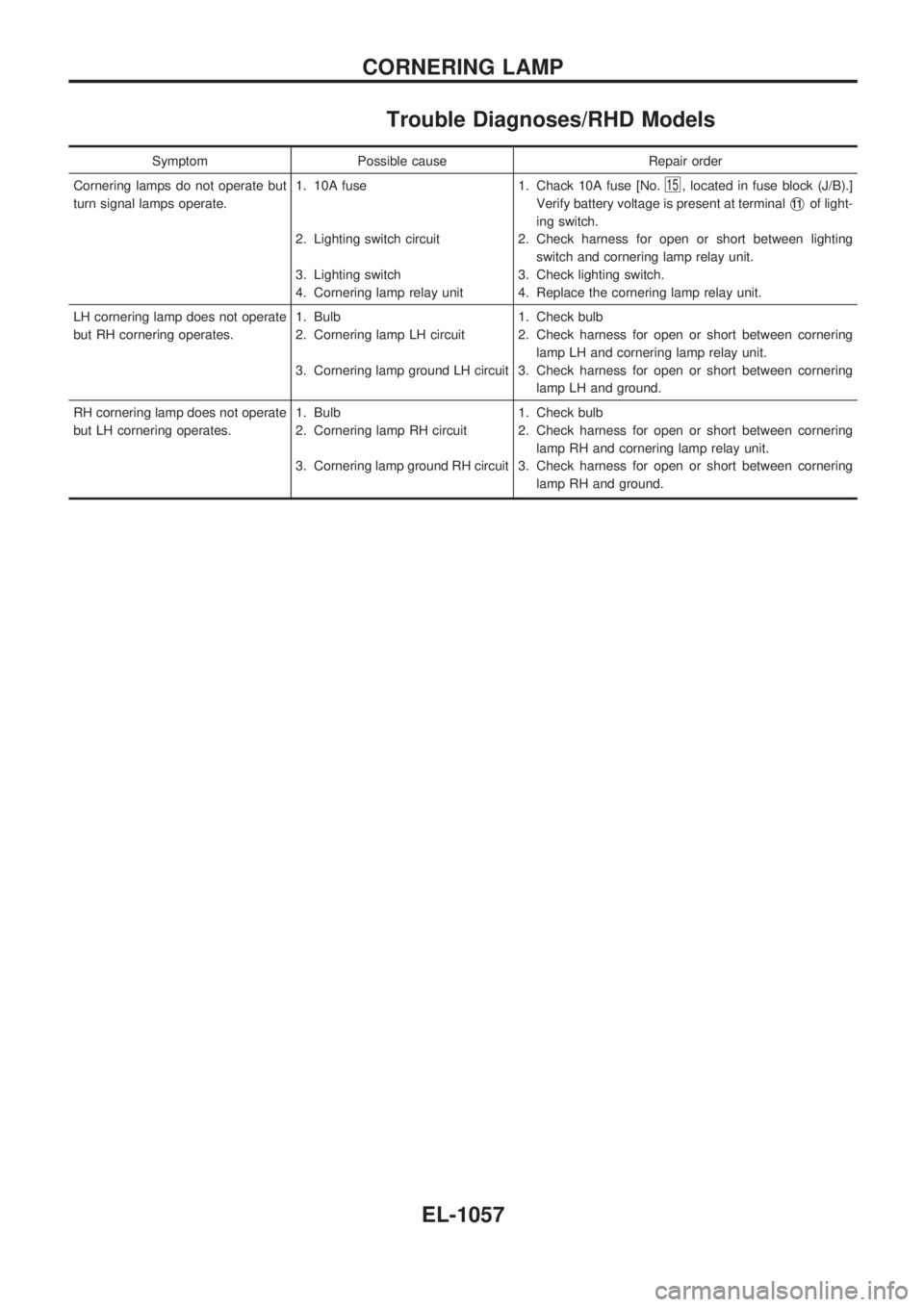
Trouble Diagnoses/RHD Models
Symptom Possible cause Repair order
Cornering lamps do not operate but
turn signal lamps operate.1. 10A fuse
2. Lighting switch circuit
3. Lighting switch
4. Cornering lamp relay unit1. Chack 10A fuse [No.
15, located in fuse block (J/B).]
Verify battery voltage is present at terminal
V11of light-
ing switch.
2. Check harness for open or short between lighting
switch and cornering lamp relay unit.
3. Check lighting switch.
4. Replace the cornering lamp relay unit.
LH cornering lamp does not operate
but RH cornering operates.1. Bulb
2. Cornering lamp LH circuit
3. Cornering lamp ground LH circuit1. Check bulb
2. Check harness for open or short between cornering
lamp LH and cornering lamp relay unit.
3. Check harness for open or short between cornering
lamp LH and ground.
RH cornering lamp does not operate
but LH cornering operates.1. Bulb
2. Cornering lamp RH circuit
3. Cornering lamp ground RH circuit1. Check bulb
2. Check harness for open or short between cornering
lamp RH and cornering lamp relay unit.
3. Check harness for open or short between cornering
lamp RH and ground.
CORNERING LAMP
EL-1057
Page 582 of 1033
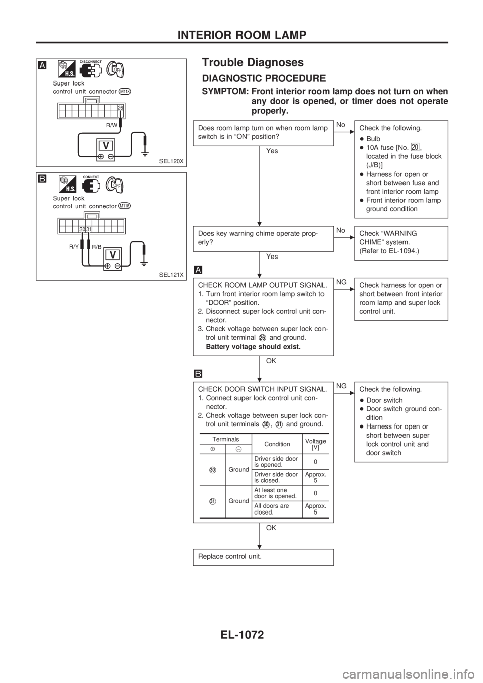
Trouble Diagnoses
DIAGNOSTIC PROCEDURE
SYMPTOM: Front interior room lamp does not turn on when
any door is opened, or timer does not operate
properly.
Does room lamp turn on when room lamp
switch is in ªONº position?
Yes
cNo
Check the following.
+Bulb
+10A fuse [No.
20,
located in the fuse block
(J/B)]
+Harness for open or
short between fuse and
front interior room lamp
+Front interior room lamp
ground condition
Does key warning chime operate prop-
erly?
Yes
cNo
Check ªWARNING
CHIMEº system.
(Refer to EL-1094.)
CHECK ROOM LAMP OUTPUT SIGNAL.
1. Turn front interior room lamp switch to
ªDOORº position.
2. Disconnect super lock control unit con-
nector.
3. Check voltage between super lock con-
trol unit terminal
V26and ground.
Battery voltage should exist.
OK
cNG
Check harness for open or
short between front interior
room lamp and super lock
control unit.
CHECK DOOR SWITCH INPUT SIGNAL.
1. Connect super lock control unit con-
nector.
2. Check voltage between super lock con-
trol unit terminals
V30,V31and ground.
OK
cNG
Check the following.
+Door switch
+Door switch ground con-
dition
+Harness for open or
short between super
lock control unit and
door switch
Replace control unit.
Terminals
ConditionVoltage
[V]
Å@
V30GroundDriver side door
is opened.0
Driver side door
is closed.Approx.
5
V31GroundAt least one
door is opened.0
All doors are
closed.Approx.
5
SEL120X
SEL121X
.
.
.
.
INTERIOR ROOM LAMP
EL-1072
Page 994 of 1033
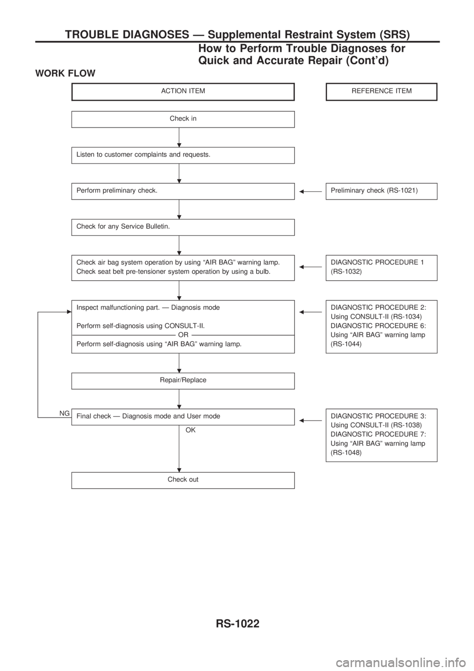
WORK FLOW
ACTION ITEMREFERENCE ITEM
Check in
Listen to customer complaints and requests.
Perform preliminary check.bPreliminary check (RS-1021)
Check for any Service Bulletin.
Check air bag system operation by using ªAIR BAGº warning lamp.
Check seat belt pre-tensioner system operation by using a bulb.bDIAGNOSTIC PROCEDURE 1
(RS-1032)
cInspect malfunctioning part. Ð Diagnosis mode
Perform self-diagnosis using CONSULT-II.
----------------------------------------------------------------------------------------------------------------------------------------------------------------------------------------------------------------------------------OR ----------------------------------------------------------------------------------------------------------------------------------------------------------------------------------------------------------------------------------
Perform self-diagnosis using ªAIR BAGº warning lamp.bDIAGNOSTIC PROCEDURE 2:
Using CONSULT-II (RS-1034)
DIAGNOSTIC PROCEDURE 6:
Using ªAIR BAGº warning lamp
(RS-1044)
Repair/Replace
NGFinal check Ð Diagnosis mode and User mode
OK
bDIAGNOSTIC PROCEDURE 3:
Using CONSULT-II (RS-1038)
DIAGNOSTIC PROCEDURE 7:
Using ªAIR BAGº warning lamp
(RS-1048)
Check out
.
.
.
.
.
.
.
.
TROUBLE DIAGNOSES Ð Supplemental Restraint System (SRS)
How to Perform Trouble Diagnoses for
Quick and Accurate Repair (Cont'd)
RS-1022
Page 1005 of 1033
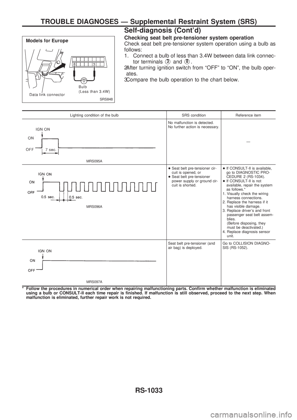
Checking seat belt pre-tensioner system operation
Check seat belt pre-tensioner system operation using a bulb as
follows:
1. Connect a bulb of less than 3.4W between data link connec-
tor terminals
V3andV8.
2.After turning ignition switch from ªOFFº to ªONº, the bulb oper-
ates.
3.Compare the bulb operation to the chart below.
Lighting condition of the bulb SRS condition Reference item
MRS095A
No malfunction is detected.
No further action is necessary.
Ð
MRS096A
+Seat belt pre-tensioner cir-
cuit is opened, or
+Seat belt pre-tensioner
power supply or ground cir-
cuit is shorted.+If CONSULT-II is available,
go to DIAGNOSTIC PRO-
CEDURE 2 (RS-1034).
+If CONSULT-II is not
available, repair the system
as follows.*
1. Visually check the wiring
harness connections.
2. Replace the harness if it
has visible damage.
3. Replace driver's and front
passenger seat belt assem-
blies.
(Before disposing, they
must be deactivated.)
4. Replace diagnosis sensor
unit.
MRS097A
Seat belt pre-tensioner (and
air bag) is deployed.Go to COLLISION DIAGNO-
SIS (RS-1052).
* Follow the procedures in numerical order when repairing malfunctioning parts. Confirm whether malfunction is eliminated
using a bulb or CONSULT-II each time repair is finished. If malfunction is still observed, proceed to the next step. When
malfunction is eliminated, further repair work is not required.
SRS848
TROUBLE DIAGNOSES Ð Supplemental Restraint System (SRS)
Self-diagnosis (Cont'd)
RS-1033