Page 233 of 1033
General Specifications
CLUTCH DISC
Model 275
Engine ZD30DDTi
Facing size
(Outer dia. x inner dia. x thickness)
mm (in)275 x 180 x 3.5
(10.83 x 7.09 x 0.138)
Thickness of disc assembly with load
mm (in)/N (kg, lb)7.7 - 8.3 (0.303 - 0.327)/
7,846 (800, 1,764)
CLUTCH COVER
Body Hardtop Except Hardtop
Model 275
Engine ZD30DDTi
Full load N (kg, lb)6,473 - 7,257
(660 - 740,
1,455 - 1,632)7,355 - 8,336
(750 - 850,
1,654 - 1,874)
Inspection and Adjustment
CLUTCH PEDAL
Unit: mm (in)
Pedal height ªH*ºZD30DDTi
195 - 205
(7.68 - 8.07)
Pedal free play ªAº (at pedal pad) 1.0 - 3.0 (0.039 - 0.118)
*: Measured from surface of melt sheet to pedal pad
SERVICE DATA AND SPECIFICATIONS (SDS)
CL-1004
Page 462 of 1033
18 CHECK GLOW PLUG
1. Remove glow plug connecting plate.
2. Check glow plug resistance.
SEF236Z
NOTE:
+Do not bump glow plug heating element. If it is bumped, replace glow plug with a new one.
+If glow plug is dropped from a height of 10 cm (3.94 in) or higher, replace with a new one.
+If glow plug installation hole is contaminated with carbon, remove it with a reamer or suitable tool.
+Hand-tighten glow plug by turning it two or three times, then tighten using a tool to specified torque.
:15-20Nzm (1.5 - 2.1 kg-m, 11 - 15 ft-lb)
OK or NG
OKcGO TO 19.
NGcReplace glow plug.
19 CHECK INTERMITTENT INCIDENT
Refer to ªTROUBLE DIAGNOSIS FOR INTERMITTENT INCIDENTº, EC-1076.
cINSPECTION END
GLOW CONTROL SYSTEMZD30DDTi
Diagnostic Procedure (Cont'd)
EC-1229
Page 549 of 1033
Service Data and Specifications (SDS)
STARTER
TypeS13-551A S14-407A
HITACHI
Reduction
Applied modelZD30
Standard Option
System voltage V 12
No-load
Terminal voltage V 11.0
Current A Less than 160
Revolution rpm More than 3,300 More than 3,400
Minimum diameter of commutator
mm (in)35.5 (1.398)
Minimum length of brush mm (in) 11.0 (0.433)
Brush spring tension
N (kg, lb)28.4 - 34.3 (2.9 - 3.5, 6.4 - 7.7)
Clearance between bearing metal
and armature shaft mm (in)Ð
Clearance ª!º between pinion
front edge and pinion stopper
mm (in)Ð
Movement ª!º in height of pinion
assembly mm (in)0.3 - 2.0 (0.012 - 0.079)
STARTING SYSTEM
EL-1039
Page 770 of 1033
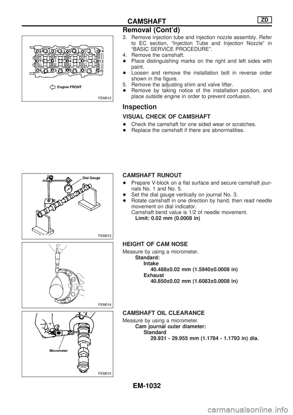
3. Remove injection tube and injection nozzle assembly. Refer
to EC section, ªInjection Tube and Injection Nozzleº in
ªBASIC SERVICE PROCEDUREº.
4. Remove the camshaft.
+Place distinguishing marks on the right and left sides with
paint.
+Loosen and remove the installation bolt in reverse order
shown in the figure.
5. Remove the adjusting shim and valve lifter.
+Remove by taking notice of the installation position, and
place outside engine in order to prevent confusion.
Inspection
VISUAL CHECK OF CAMSHAFT
+Check the camshaft for one sided wear or scratches.
+Replace the camshaft if there are abnormalities.
CAMSHAFT RUNOUT
+Prepare V-block on a flat surface and secure camshaft jour-
nals No. 1 and No. 5.
+Set the dial gauge vertically on journal No. 3.
+Rotate camshaft in one direction by hand, then read needle
movement on dial indicator.
Camshaft bend value is 1/2 of needle movement.
Limit: 0.02 mm (0.0008 in)
HEIGHT OF CAM NOSE
Measure by using a micrometer.
Standard:
Intake
40.488 0.02 mm (1.5940 0.0008 in)
Exhaust
40.850 0.02 mm (1.6083 0.0008 in)
CAMSHAFT OIL CLEARANCE
Measure by using a micrometer.
Cam journal outer diameter:
Standard
29.931 - 29.955 mm (1.1784 - 1.1793 in) dia.
FEM012
FEM013
FEM014
FEM015
CAMSHAFTZD
Removal (Cont'd)
EM-1032
Page 792 of 1033
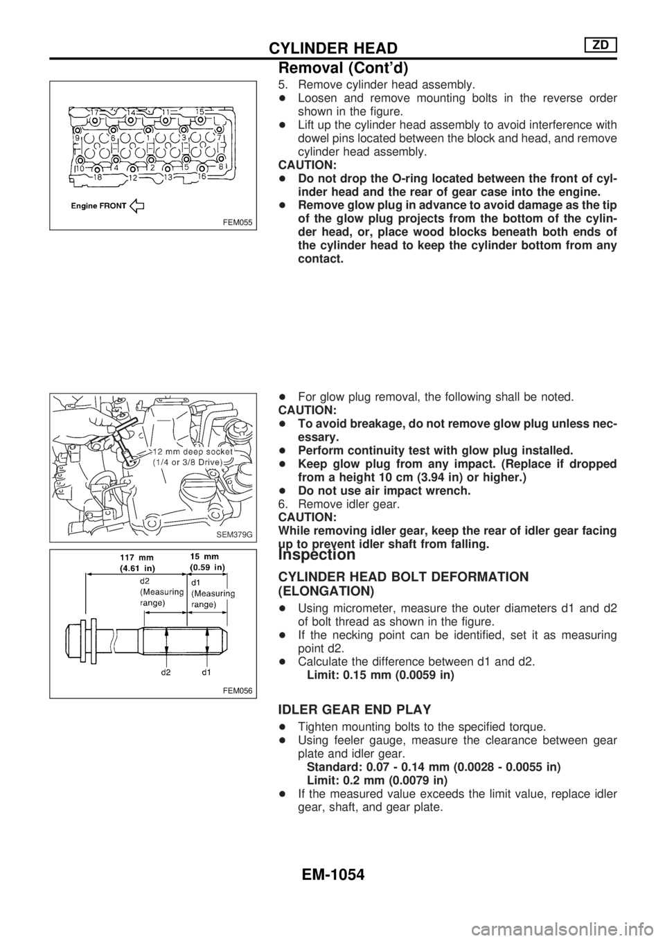
5. Remove cylinder head assembly.
+Loosen and remove mounting bolts in the reverse order
shown in the figure.
+Lift up the cylinder head assembly to avoid interference with
dowel pins located between the block and head, and remove
cylinder head assembly.
CAUTION:
+Do not drop the O-ring located between the front of cyl-
inder head and the rear of gear case into the engine.
+Remove glow plug in advance to avoid damage as the tip
of the glow plug projects from the bottom of the cylin-
der head, or, place wood blocks beneath both ends of
the cylinder head to keep the cylinder bottom from any
contact.
+For glow plug removal, the following shall be noted.
CAUTION:
+To avoid breakage, do not remove glow plug unless nec-
essary.
+Perform continuity test with glow plug installed.
+Keep glow plug from any impact. (Replace if dropped
from a height 10 cm (3.94 in) or higher.)
+Do not use air impact wrench.
6. Remove idler gear.
CAUTION:
While removing idler gear, keep the rear of idler gear facing
up to prevent idler shaft from falling.
Inspection
CYLINDER HEAD BOLT DEFORMATION
(ELONGATION)
+Using micrometer, measure the outer diameters d1 and d2
of bolt thread as shown in the figure.
+If the necking point can be identified, set it as measuring
point d2.
+Calculate the difference between d1 and d2.
Limit: 0.15 mm (0.0059 in)
IDLER GEAR END PLAY
+Tighten mounting bolts to the specified torque.
+Using feeler gauge, measure the clearance between gear
plate and idler gear.
Standard: 0.07 - 0.14 mm (0.0028 - 0.0055 in)
Limit: 0.2 mm (0.0079 in)
+If the measured value exceeds the limit value, replace idler
gear, shaft, and gear plate.
FEM055
SEM379G
FEM056
CYLINDER HEADZD
Removal (Cont'd)
EM-1054
Page 793 of 1033
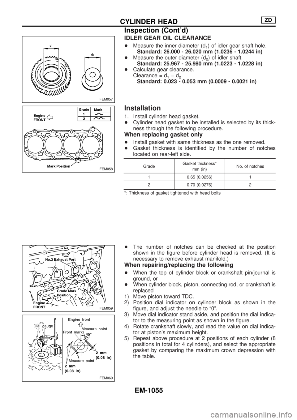
IDLER GEAR OIL CLEARANCE
+Measure the inner diameter (d1) of idler gear shaft hole.
Standard: 26.000 - 26.020 mm (1.0236 - 1.0244 in)
+Measure the outer diameter (d
2) of idler shaft.
Standard: 25.967 - 25.980 mm (1.0223 - 1.0228 in)
+Calculate gear clearance.
Clearance = d
1þd2Standard: 0.023 - 0.053 mm (0.0009 - 0.0021 in)
Installation
1. Install cylinder head gasket.
+Cylinder head gasket to be installed is selected by its thick-
ness through the following procedure.
When replacing gasket only
+Install gasket with same thickness as the one removed.
+Gasket thickness is identified by the number of notches
located on rear-left side.
GradeGasket thickness*
mm (in)No. of notches
1 0.65 (0.0256) 1
2 0.70 (0.0276) 2
*: Thickness of gasket tightened with head bolts
+The number of notches can be checked at the position
shown in the figure before cylinder head is removed. (It is
necessary to remove exhaust manifold.)
When repairing/replacing the following
+When the top of cylinder block or crankshaft pin/journal is
ground, or
+When cylinder block, piston, connecting rod, or crankshaft is
replaced
1) Move piston toward TDC.
2) Position dial indicator on cylinder block as shown in the
figure, and adjust the needle to ª0º.
3) Move dial indicator stand aside, and position the dial indica-
tor to the measuring point as shown in the figure.
4) Rotate crankshaft slowly, and read the value on dial indica-
tor at piston's maximum height.
5) Repeat above procedure at 2 positions of each cylinder (8
positions in total for 4 cylinders), and select the appropriate
gasket by comparing the maximum crown depression with
the table.
FEM057
FEM058
FEM059
FEM060
CYLINDER HEADZD
Inspection (Cont'd)
EM-1055
Page 800 of 1033
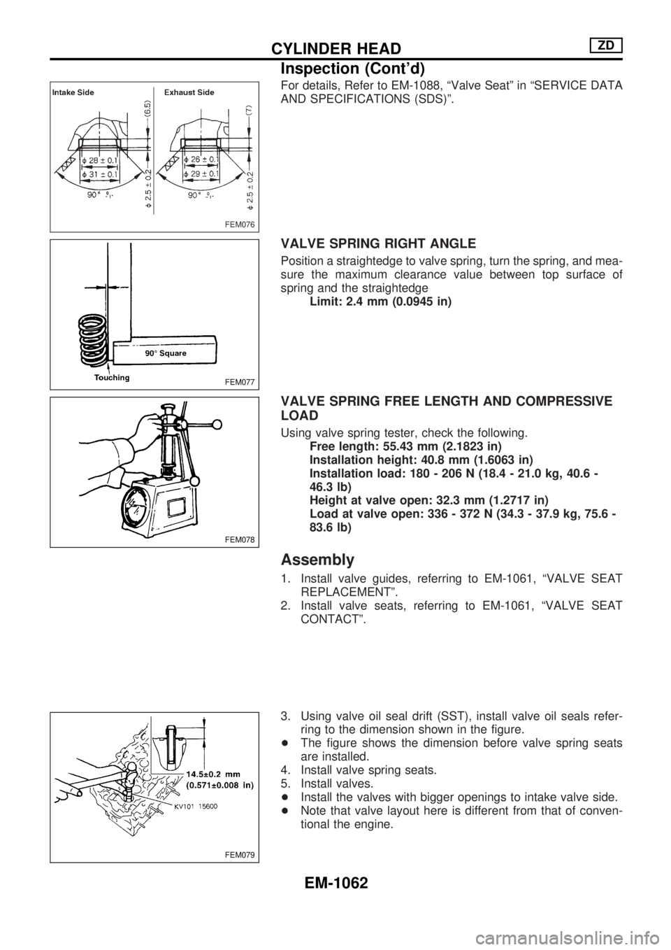
For details, Refer to EM-1088, ªValve Seatº in ªSERVICE DATA
AND SPECIFICATIONS (SDS)º.
VALVE SPRING RIGHT ANGLE
Position a straightedge to valve spring, turn the spring, and mea-
sure the maximum clearance value between top surface of
spring and the straightedge
Limit: 2.4 mm (0.0945 in)
VALVE SPRING FREE LENGTH AND COMPRESSIVE
LOAD
Using valve spring tester, check the following.
Free length: 55.43 mm (2.1823 in)
Installation height: 40.8 mm (1.6063 in)
Installation load: 180 - 206 N (18.4 - 21.0 kg, 40.6 -
46.3 lb)
Height at valve open: 32.3 mm (1.2717 in)
Load at valve open: 336 - 372 N (34.3 - 37.9 kg, 75.6 -
83.6 lb)
Assembly
1. Install valve guides, referring to EM-1061, ªVALVE SEAT
REPLACEMENTº.
2. Install valve seats, referring to EM-1061, ªVALVE SEAT
CONTACTº.
3. Using valve oil seal drift (SST), install valve oil seals refer-
ring to the dimension shown in the figure.
+The figure shows the dimension before valve spring seats
are installed.
4. Install valve spring seats.
5. Install valves.
+Install the valves with bigger openings to intake valve side.
+Note that valve layout here is different from that of conven-
tional the engine.
FEM076
FEM077
FEM078
FEM079
CYLINDER HEADZD
Inspection (Cont'd)
EM-1062
Page 818 of 1033
CAUTION:
If out of specification, take same action mentioned in
ªMethod by measurementº.
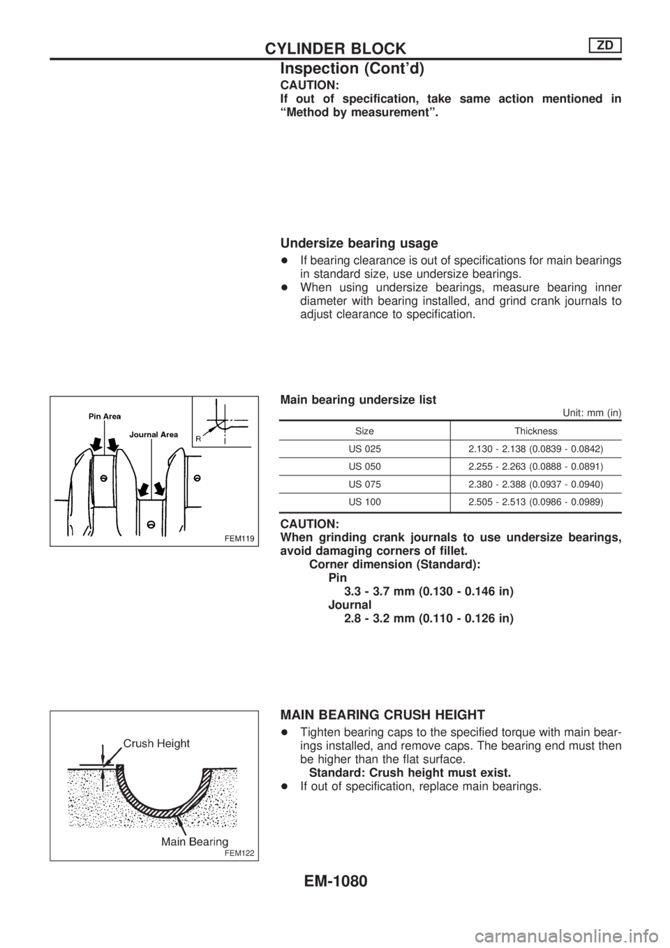
Undersize bearing usage
+If bearing clearance is out of specifications for main bearings
in standard size, use undersize bearings.
+When using undersize bearings, measure bearing inner
diameter with bearing installed, and grind crank journals to
adjust clearance to specification.
Main bearing undersize list
Unit: mm (in)
Size Thickness
US 025 2.130 - 2.138 (0.0839 - 0.0842)
US 050 2.255 - 2.263 (0.0888 - 0.0891)
US 075 2.380 - 2.388 (0.0937 - 0.0940)
US 100 2.505 - 2.513 (0.0986 - 0.0989)
CAUTION:
When grinding crank journals to use undersize bearings,
avoid damaging corners of fillet.
Corner dimension (Standard):
Pin
3.3 - 3.7 mm (0.130 - 0.146 in)
Journal
2.8 - 3.2 mm (0.110 - 0.126 in)
MAIN BEARING CRUSH HEIGHT
+Tighten bearing caps to the specified torque with main bear-
ings installed, and remove caps. The bearing end must then
be higher than the flat surface.
Standard: Crush height must exist.
+If out of specification, replace main bearings.
FEM119
FEM122
CYLINDER BLOCKZD
Inspection (Cont'd)
EM-1080