2000 NISSAN PATROL radiator cap
[x] Cancel search: radiator capPage 339 of 1033
ECM Terminals and Reference Value
Specification data are reference values and are measured between each terminal and ground.
CAUTION:
Do not use ECM ground terminals when measuring input/output voltage. Doing so may damage the
ECM's transistor. Use a ground other than ECM terminals, such as the ground.
TER-
MINAL
NO.WIRE
COLORITEM CONDITION DATA (DC Voltage)
14 L Cooling fan relayEngine is running.
Cooling fan is not operatingBATTERY VOLTAGE
(11 - 14V)
Engine is running.
Cooling fan is operatingApproximately 0.1V
On Board Diagnosis Logic
This diagnosis continuously monitors the engine coolant temperature.
If the cooling fan or another component in the cooling system malfunctions, engine coolant temperature will
rise.
When the engine coolant temperature reaches an abnormally high temperature condition, a malfunction is
indicated.
Malfunction is detected when ... Check Items (Possible Cause)
+Cooling fan does not operate properly (Overheat).
+Cooling fan system does not operate properly (Overheat).
+Engine coolant was not added to the system using the proper
filling method.+Harness or connectors
(The cooling fan circuit is open or shorted.)
+Cooling fan
+Radiator hose
+Radiator
+Radiator cap
+Water pump
+Thermostat
+Fan belt
+Engine coolant temperature sensor
For more information, refer to ªMAIN 12 CAUSES OF
OVERHEATINGº, EC-1116.
CAUTION:
When a malfunction is indicated, be sure to replace the coolant following the procedure in the MA
section (ªChanging Engine Coolantº, ªENGINE MAINTENANCEº). Also, replace the engine oil.
1) Fill radiator with coolant up to specified level with a filling speed of 2 liters per minute. Be sure
to use coolant with the proper mixture ratio. Refer to MA section (ªAnti-freeze Coolant Mixture
Ratioº, ªRECOMMENDED LUBRICANTS AND FLUIDSº).
2) After refilling coolant, run engine to ensure that no water-flow noise is emitted.
DTC 0208 OVER HEATZD30DDTi
EC-1106
Page 340 of 1033
Overall Function Check
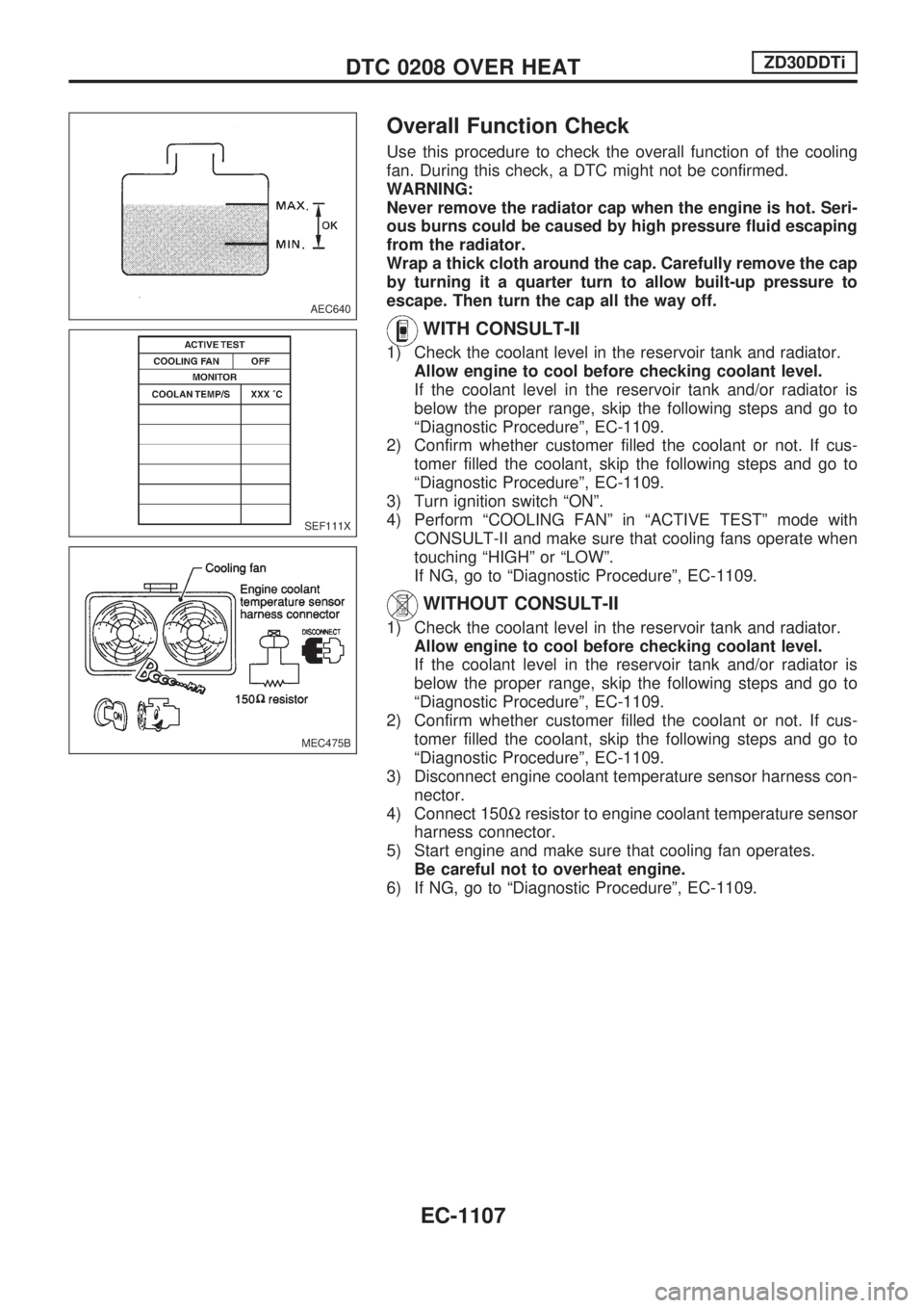
Use this procedure to check the overall function of the cooling
fan. During this check, a DTC might not be confirmed.
WARNING:
Never remove the radiator cap when the engine is hot. Seri-
ous burns could be caused by high pressure fluid escaping
from the radiator.
Wrap a thick cloth around the cap. Carefully remove the cap
by turning it a quarter turn to allow built-up pressure to
escape. Then turn the cap all the way off.
WITH CONSULT-II
1) Check the coolant level in the reservoir tank and radiator.
Allow engine to cool before checking coolant level.
If the coolant level in the reservoir tank and/or radiator is
below the proper range, skip the following steps and go to
ªDiagnostic Procedureº, EC-1109.
2) Confirm whether customer filled the coolant or not. If cus-
tomer filled the coolant, skip the following steps and go to
ªDiagnostic Procedureº, EC-1109.
3) Turn ignition switch ªONº.
4) Perform ªCOOLING FANº in ªACTIVE TESTº mode with
CONSULT-II and make sure that cooling fans operate when
touching ªHIGHº or ªLOWº.
If NG, go to ªDiagnostic Procedureº, EC-1109.
WITHOUT CONSULT-II
1) Check the coolant level in the reservoir tank and radiator.
Allow engine to cool before checking coolant level.
If the coolant level in the reservoir tank and/or radiator is
below the proper range, skip the following steps and go to
ªDiagnostic Procedureº, EC-1109.
2) Confirm whether customer filled the coolant or not. If cus-
tomer filled the coolant, skip the following steps and go to
ªDiagnostic Procedureº, EC-1109.
3) Disconnect engine coolant temperature sensor harness con-
nector.
4) Connect 150Wresistor to engine coolant temperature sensor
harness connector.
5) Start engine and make sure that cooling fan operates.
Be careful not to overheat engine.
6) If NG, go to ªDiagnostic Procedureº, EC-1109.
AEC640
SEF111X
MEC475B
DTC 0208 OVER HEATZD30DDTi
EC-1107
Page 347 of 1033
12 CHECK COOLING SYSTEM FOR LEAK
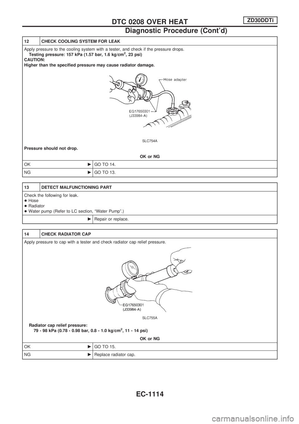
Apply pressure to the cooling system with a tester, and check if the pressure drops.
Testing pressure: 157 kPa (1.57 bar, 1.6 kg/cm
2, 23 psi)
CAUTION:
Higher than the specified pressure may cause radiator damage.
SLC754A
Pressure should not drop.
OK or NG
OKcGO TO 14.
NGcGO TO 13.
13 DETECT MALFUNCTIONING PART
Check the following for leak.
+Hose
+Radiator
+Water pump (Refer to LC section, ªWater Pumpº.)
cRepair or replace.
14 CHECK RADIATOR CAP
Apply pressure to cap with a tester and check radiator cap relief pressure.
SLC755A
Radiator cap relief pressure:
79 - 98 kPa (0.78 - 0.98 bar, 0.8 - 1.0 kg/cm2, 11 - 14 psi)
OK or NG
OKcGO TO 15.
NGcReplace radiator cap.
DTC 0208 OVER HEATZD30DDTi
Diagnostic Procedure (Cont'd)
EC-1114
Page 349 of 1033
17 CHECK MAIN 12 CAUSES
If the cause cannot be isolated, go to ªMAIN 12 CAUSES OF OVERHEATINGº, EC-1116.
cINSPECTION END
Main 12 Causes of Overheating
Engine Step Inspection item Equipment Standard Reference page
OFF 1+Blocked radiator
+Blocked condenser
+Blocked radiator grille
+Blocked bumper+Visual No blocking Ð
2+Coolant mixture+Coolant tester 30 - 50% coolant mixture See ªRECOMMENDED
FLUIDS AND LUBRI-
CANTSº in MA section.
3+Coolant level+Visual Coolant up to MAX level
in reservoir tank and
radiator filler neckSee ªChanging Engine
Coolantº, ªENGINE MAIN-
TENANCEº in MA sec-
tion.
4+Radiator cap+Pressure tester 78 - 98 kPa
(0.78 - 0.98 bar, 0.8 - 1.0
kg/cm
2, 11 - 14 psi)
59 - 98 kPa (0.59 - 0.98
bar, 0.6 - 1.0 kg/cm
2,
9 - 14 psi) (Limit)See ªSystem Checkº,
ªENGINE COOLING SYS-
TEMº in LC section.
ON*2 5+Coolant leaks+Visual No leaks See ªSystem Checkº,
ªENGINE COOLING SYS-
TEMº in LC section.
ON*2 6+Thermostat+Touch the upper and
lower radiator hosesBoth hoses should be hot. See ªThermostatº and
ªRadiatorº, ªENGINE
COOLING SYSTEMº in
LC section.
ON*1 7+Cooling fan+Visual Operating See ªDTC 0208 OVER
HEATº, EC-1105.
OFF 8+Combustion gas leak+Color checker chemical
tester 4 gas analyzerNegative Ð
ON*3 9+Coolant temperature
gauge+Visual Gauge less than 3/4
when drivingÐ
+Coolant overflow to res-
ervoir tank+Visual No overflow during driving
and idlingSee ªChanging Engine
Coolantº, ªENGINE MAIN-
TENANCEº in MA sec-
tion.
OFF*4 10+Coolant return from res-
ervoir tank to radiator+Visual Should be initial level in
reservoir tankSee ªENGINE MAINTE-
NANCEº in MA section.
OFF 11+Cylinder head+Straight gauge feeler
gauge0.1 mm (0.004 in) Maxi-
mum distortion (warping)See ªInspectionº, ªCYLIN-
DER HEADº in EM sec-
tion.
12+Cylinder block and pis-
tons+Visual No scuffing on cylinder
walls or pistonSee ªInspectionº, ªCYLIN-
DER BLOCKº in EM sec-
tion.
*1: Engine running at idle.
*2: Engine running at 3,000 rpm for 10 minutes.
*3: Drive at 90 km/h (55 MPH) for 30 minutes and then let idle for 10 minutes.
*4: After 60 minutes of cool down time.
For more information, refer to ªOVERHEATING CAUSE ANALYSISº in LC section.
DTC 0208 OVER HEATZD30DDTi
Diagnostic Procedure (Cont'd)
EC-1116
Page 892 of 1033
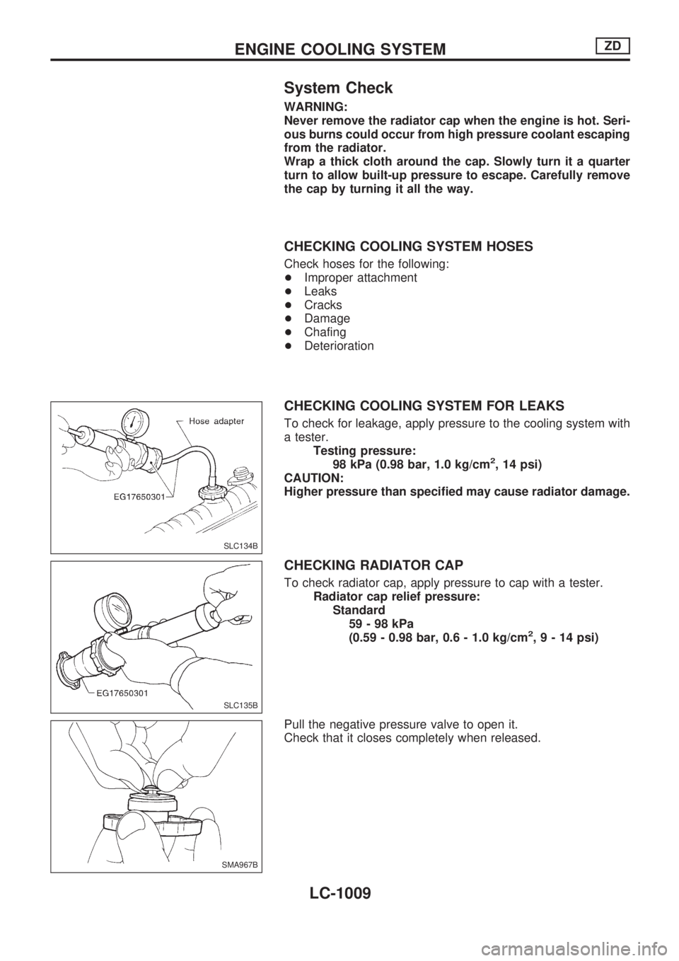
System Check
WARNING:
Never remove the radiator cap when the engine is hot. Seri-
ous burns could occur from high pressure coolant escaping
from the radiator.
Wrap a thick cloth around the cap. Slowly turn it a quarter
turn to allow built-up pressure to escape. Carefully remove
the cap by turning it all the way.
CHECKING COOLING SYSTEM HOSES
Check hoses for the following:
+Improper attachment
+Leaks
+Cracks
+Damage
+Chafing
+Deterioration
CHECKING COOLING SYSTEM FOR LEAKS
To check for leakage, apply pressure to the cooling system with
a tester.
Testing pressure:
98 kPa (0.98 bar, 1.0 kg/cm
2, 14 psi)
CAUTION:
Higher pressure than specified may cause radiator damage.
CHECKING RADIATOR CAP
To check radiator cap, apply pressure to cap with a tester.
Radiator cap relief pressure:
Standard
59-98kPa
(0.59 - 0.98 bar, 0.6 - 1.0 kg/cm
2,9-14psi)
Pull the negative pressure valve to open it.
Check that it closes completely when released.
SLC134B
SLC135B
SMA967B
ENGINE COOLING SYSTEMZD
LC-1009
Page 893 of 1033
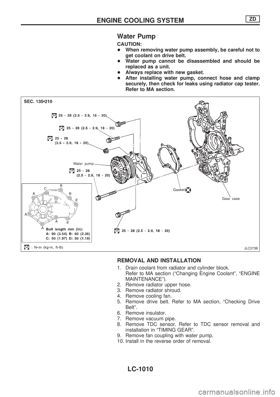
Water Pump
CAUTION:
+When removing water pump assembly, be careful not to
get coolant on drive belt.
+Water pump cannot be disassembled and should be
replaced as a unit.
+Always replace with new gasket.
+After installing water pump, connect hose and clamp
securely, then check for leaks using radiator cap tester.
Refer to MA section.
REMOVAL AND INSTALLATION
1. Drain coolant from radiator and cylinder block.
Refer to MA section (ªChanging Engine Coolantº, ªENGINE
MAINTENANCEº).
2. Remove radiator upper hose.
3. Remove radiator shroud.
4. Remove cooling fan.
5. Remove drive belt. Refer to MA section, ªChecking Drive
Beltº.
6. Remove insulator.
7. Remove vacuum pipe.
8. Remove TDC sensor. Refer to TDC sensor removal and
installation in ªTIMING GEARº.
9. Remove fan coupling with water pump.
10. Install in the reverse order of removal.
JLC373B
ENGINE COOLING SYSTEMZD
LC-1010
Page 898 of 1033
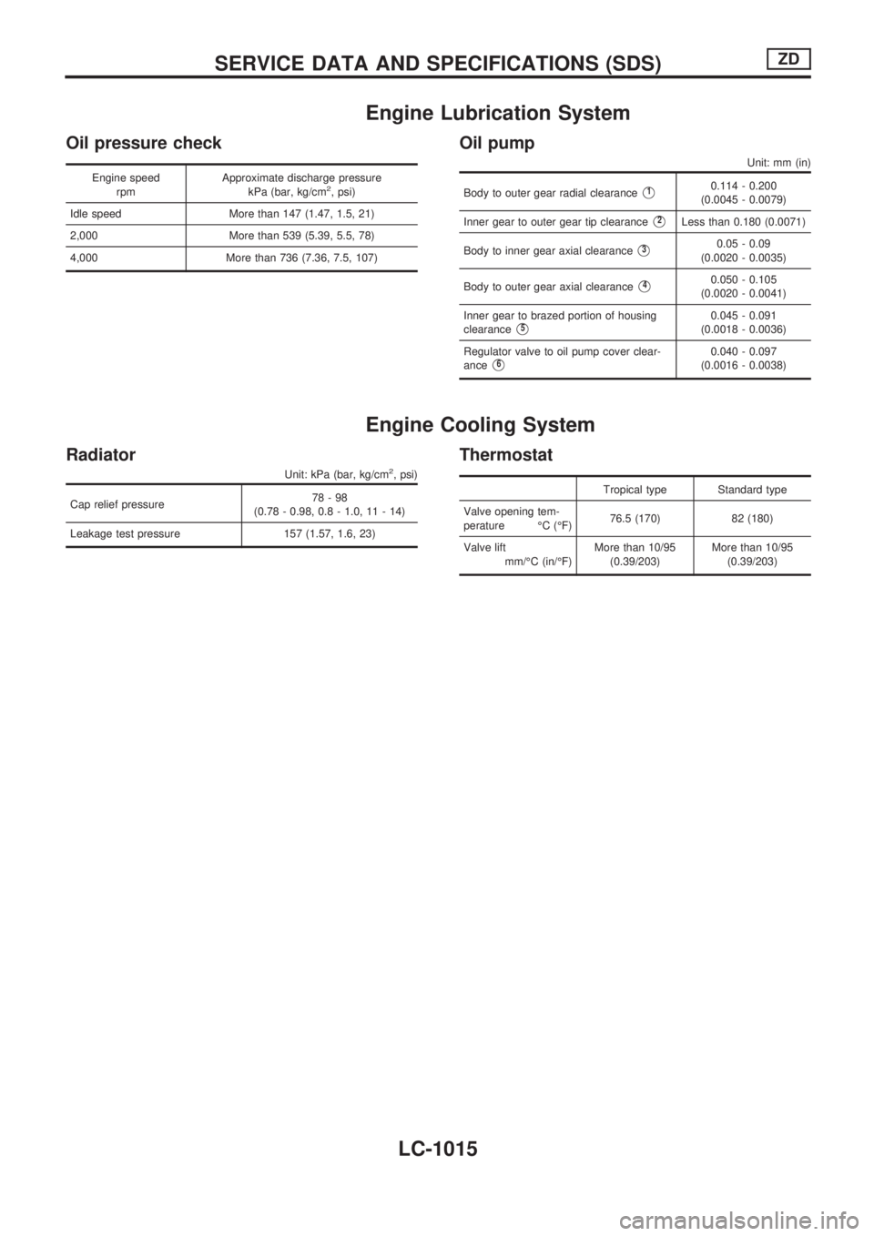
Engine Lubrication System
Oil pressure check
Engine speed
rpmApproximate discharge pressure
kPa (bar, kg/cm2, psi)
Idle speed More than 147 (1.47, 1.5, 21)
2,000 More than 539 (5.39, 5.5, 78)
4,000 More than 736 (7.36, 7.5, 107)
Oil pump
Unit: mm (in)
Body to outer gear radial clearanceV10.114 - 0.200
(0.0045 - 0.0079)
Inner gear to outer gear tip clearance
V2Less than 0.180 (0.0071)
Body to inner gear axial clearance
V30.05 - 0.09
(0.0020 - 0.0035)
Body to outer gear axial clearance
V40.050 - 0.105
(0.0020 - 0.0041)
Inner gear to brazed portion of housing
clearance
V50.045 - 0.091
(0.0018 - 0.0036)
Regulator valve to oil pump cover clear-
ance
V60.040 - 0.097
(0.0016 - 0.0038)
Engine Cooling System
Radiator
Unit: kPa (bar, kg/cm2, psi)
Cap relief pressure78-98
(0.78 - 0.98, 0.8 - 1.0, 11 - 14)
Leakage test pressure 157 (1.57, 1.6, 23)
Thermostat
Tropical type Standard type
Valve opening tem-
perature ÉC (ÉF)76.5 (170) 82 (180)
Valve lift
mm/ÉC (in/ÉF)More than 10/95
(0.39/203)More than 10/95
(0.39/203)
SERVICE DATA AND SPECIFICATIONS (SDS)ZD
LC-1015
Page 908 of 1033
Engine Coolant Mixture Ratio
The engine cooling system is filled at the factory with a high-
quality, year-round and extended life engine coolant. The high
quality engine coolant contains the specific solutions effective for
the anti-corrosion and the anti-freeze function. Therefore, addi-
tional cooling system additives are not necessary.
CAUTION:
+When adding or replacing coolant, be sure to use only
Genuine Nissan Anti-freeze Coolant (L2N) or equivalent.
Because L2N is premixed type coolant (Mixture ratio
50%).
The use of other types of engine coolant may damage your
cooling system.
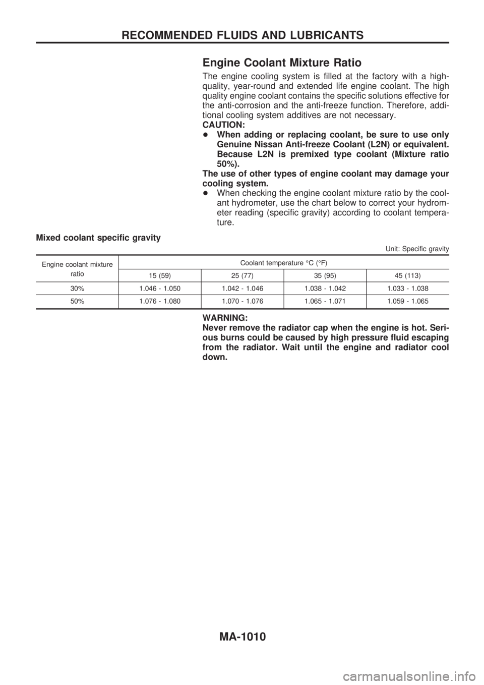
+When checking the engine coolant mixture ratio by the cool-
ant hydrometer, use the chart below to correct your hydrom-
eter reading (specific gravity) according to coolant tempera-
ture.
Mixed coolant specific gravity
Unit: Specific gravity
Engine coolant mixture
ratioCoolant temperature ÉC (ÉF)
15 (59) 25 (77) 35 (95) 45 (113)
30% 1.046 - 1.050 1.042 - 1.046 1.038 - 1.042 1.033 - 1.038
50% 1.076 - 1.080 1.070 - 1.076 1.065 - 1.071 1.059 - 1.065
WARNING:
Never remove the radiator cap when the engine is hot. Seri-
ous burns could be caused by high pressure fluid escaping
from the radiator. Wait until the engine and radiator cool
down.
RECOMMENDED FLUIDS AND LUBRICANTS
MA-1010