2000 NISSAN PATROL sport mode
[x] Cancel search: sport modePage 4 of 1033

Diagnostic Procedure....................................... 1088
TROUBLE DIAGNOSIS FOR CONTROL UNIT
(EFP ROM)........................................................... 1089
Description ....................................................... 1089
Diagnostic Procedure....................................... 1090
TROUBLE DIAGNOSIS FOR
NON-DETECTABLE ITEMS................................ 1091
PNP, Overdrive Control, A/T Mode or
Accelerator Position Switches ......................... 1091
DIAGNOSTIC PROCEDURES FOR
SYMPTOMS......................................................... 1097
1. SPORT Indicator Lamp Does Not
Come On.......................................................... 1097
2. SPORT Indicator Lamp Does Not
Come On.......................................................... 1098
3. O/D OFF Indicator Lamp Does Not Come
On .................................................................... 1098
4. SPORT Indicator Lamp Does Not
Come On.......................................................... 1099
5. Engine Cannot Be Started In ªPº and ªNº
Position ............................................................ 1100
6. In ªPº Position, Vehicle Moves Forward Or
Backward When Pushed ................................. 1100
7. In ªNº Position, Vehicle Moves .................... 1101
8. Large Shock. ªNº®ªRº Position ................ 1102
9. Vehicle Does Not Creep Backward In ªRº
Position ............................................................ 1103
10. Vehicle Does Not Creep Forward In ªDº,
ª2º Or ª1º Position ............................................ 1104
11. Vehicle Cannot Be Started From D
1......... 1105
12. A/T Does Not Shift: D
1®D2Or Does Not
Kickdown: D
4®D2......................................... 1106
13. A/T Does Not Shift: D
2®D3.................... 1107
14. A/T Does Not Shift: D
3®D4.................... 1108
15. A/T Does Not Perform Lock-up ................. 1109
16. A/T Does Not Hold Lock-up Condition ...... 1110
17. Lock-up Is Not Released ........................... 1110
18. Engine Speed Does Not Return To Idle
(Light Braking D
4®D3) .................................. 1111
19. Vehicle Does Not Start From D
1............... 1112
20. A/T Does Not Shift: D
2®D1When
Depressing Accelerator Pedal ......................... 1113
21. A/T Does Not Shift: D
4®D3, When
Overdrive Control Switch ªONº®ªOFFº ........ 1114
22. A/T Does Not Shift: D
3®22, When
Selector Lever ªDº®ª2º Position ................... 1114
23. A/T Does Not Shift: 2
2®11, WhenSelector Lever ª2º®ª1º Position .................... 1115
24. Vehicle Does Not Decelerate By Engine
Brake ................................................................ 1115
TROUBLE DIAGNOSES Ð A/T Shift Lock
System................................................................. 1116
Description ....................................................... 1116
Wiring Diagram Ð SHIFT Ð ........................... 1117
Diagnostic Procedure....................................... 1118
Key Interlock Cable.......................................... 1121
Component Check ........................................... 1122
ON-VEHICLE SERVICE...................................... 1124
Control Valve Assembly and Accumulators .... 1124
Revolution Sensor Replacement ..................... 1125
Rear Oil Seal Replacement ............................. 1125
Parking Pawl Components Inspection ............. 1125
PNP Switch Adjustment ................................... 1125
Manual Control Linkage Adjustment................ 1126
REMOVAL AND INSTALLATION....................... 1127
Removal ........................................................... 1127
Installation ........................................................ 1128
MAJOR OVERHAUL........................................... 1129
Oil Channel ...................................................... 1131
Locations of Needle Bearings, Thrust Washers
and Snap Rings ............................................... 1132
DISASSEMBLY.................................................... 1133
REPAIR FOR COMPONENT PARTS................. 1144
Oil Pump .......................................................... 1144
Control Valve Assembly................................... 1148
Control Valve Upper Body ............................... 1154
Control Valve Lower Body ............................... 1159
Reverse Clutch ................................................ 1161
High Clutch ...................................................... 1165
Forward and Overrun Clutches ....................... 1167
Low & Reverse Brake ...................................... 1171
Forward Clutch Drum Assembly ...................... 1175
Rear Internal Gear and Forward Clutch Hub .. 1177
Band Servo Piston Assembly .......................... 1180
Parking Pawl Components .............................. 1184
ASSEMBLY.......................................................... 1186
Assembly (1) .................................................... 1186
Adjustment ....................................................... 1190
Assembly (2) .................................................... 1195
A/T FLUID COOLER SYSTEM........................... 1205
A/T Fluid Cooler ............................................... 1205
SERVICE DATA AND SPECIFICATIONS (SDS)1206
General Specifications ..................................... 1206
Specifications and Adjustment......................... 1206
When you read wiring diagrams:
+Read GI section, ªHOW TO READ WIRING DIAGRAMSº.
+See EL section, ªPOWER SUPPLY ROUTINGº for power distribution circuit.
When you perform trouble diagnoses, read GI section, ªHOW TO FOLLOW FLOW
CHART IN TROUBLE DIAGNOSESº.
AT-1002
Page 8 of 1033
Service Notice or Precautions
FAIL-SAFE
The TCM has an electronic Fail-Safe (limp home mode). This allows the vehicle to be driven even if a major
electrical input/output device circuit is damaged.
Under Fail-Safe, the vehicle always runs in third gear even with a shift lever position of ª1º, ª2º or ªDº. Cus-
tomer may complain of ªsluggish or poor accelerationº.
When the Fail-Safe operation occurs the next time the key is turned to the ªONº position, the SPORT indi-
cator lamp will blink for about 8 seconds. (For diagnosis, refer to AT-1029.)
The blinking of the SPORT indicator lamp for about 8 seconds will appear only once and be cleared. The
customer may resume normal driving conditions by chance.
Always follow the ªWORK FLOWº (Refer to AT-1040).
The SELF-DIAGNOSIS results will be as follows:
The first SELF-DIAGNOSIS will indicate the damage of the vehicle speed sensor or the revolution
sensor.
During the next SELF-DIAGNOSIS performed after checking the sensor, no damages will be indicated.
PREPARATION AND PRECAUTIONS
AT-1006
Page 27 of 1033
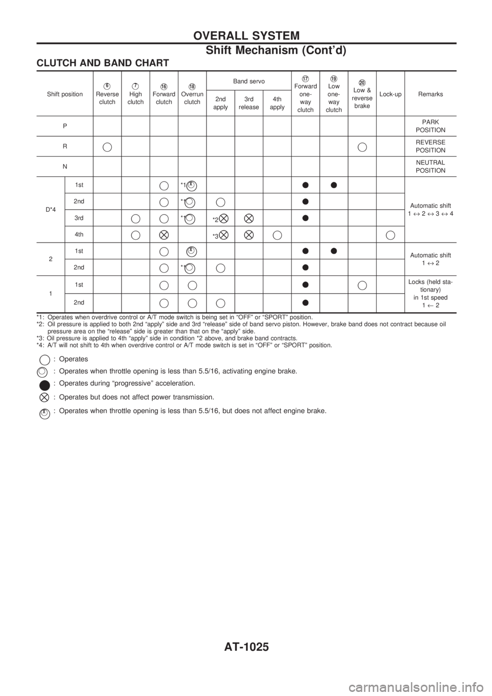
CLUTCH AND BAND CHART
Shift positionV6
Reverse
clutchV7
High
clutchV16Forward
clutchV18Overrun
clutchBand servo
V17Forward
one-
way
clutchV19Low
one-
way
clutchV20Low &
reverse
brakeLock-up Remarks
2nd
apply3rd
release4th
apply
PPARK
POSITION
R
jjREVERSE
POSITION
NNEUTRAL
POSITION
D*41st
j*1jVX++
Automatic shift
1«2«3«4 2ndj*1jVj+
3rdjj*1jV*2^^+
4thj^*3^^jj
21stjjVX++Automatic shift
1«2
2nd
j*1jVj+
11stjj+jLocks (held sta-
tionary)
in 1st speed
1¬2 2nd
jjj+
*1: Operates when overdrive control or A/T mode switch is being set in ªOFFº or ªSPORTº position.
*2: Oil pressure is applied to both 2nd ªapplyº side and 3rd ªreleaseº side of band servo piston. However, brake band does not contract because oil
pressure area on the ªreleaseº side is greater than that on the ªapplyº side.
*3: Oil pressure is applied to 4th ªapplyº side in condition *2 above, and brake band contracts.
*4: A/T will not shift to 4th when overdrive control or A/T mode switch is set in ªOFFº or ªSPORTº position.
j: Operates
: Operates when throttle opening is less than 5.5/16, activating engine brake.
*: Operates during ªprogressiveº acceleration.
^: Operates but does not affect power transmission.
jVX: Operates when throttle opening is less than 5.5/16, but does not affect engine brake.
jV
OVERALL SYSTEM
Shift Mechanism (Cont'd)
AT-1025
Page 28 of 1033
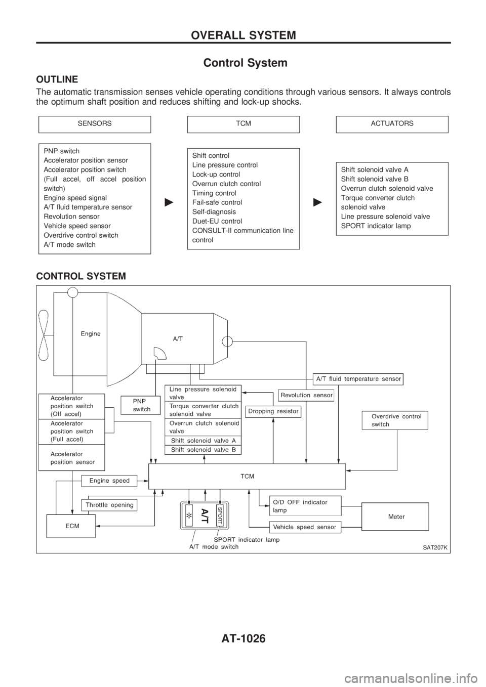
Control System
OUTLINE
The automatic transmission senses vehicle operating conditions through various sensors. It always controls
the optimum shaft position and reduces shifting and lock-up shocks.
SENSORSTCMACTUATORS
PNP switch
Accelerator position sensor
Accelerator position switch
(Full accel, off accel position
switch)
Engine speed signal
A/T fluid temperature sensor
Revolution sensor
Vehicle speed sensor
Overdrive control switch
A/T mode switch
c
Shift control
Line pressure control
Lock-up control
Overrun clutch control
Timing control
Fail-safe control
Self-diagnosis
Duet-EU control
CONSULT-II communication line
control
c
Shift solenoid valve A
Shift solenoid valve B
Overrun clutch solenoid valve
Torque converter clutch
solenoid valve
Line pressure solenoid valve
SPORT indicator lamp
CONTROL SYSTEM
SAT207K
OVERALL SYSTEM
AT-1026
Page 29 of 1033
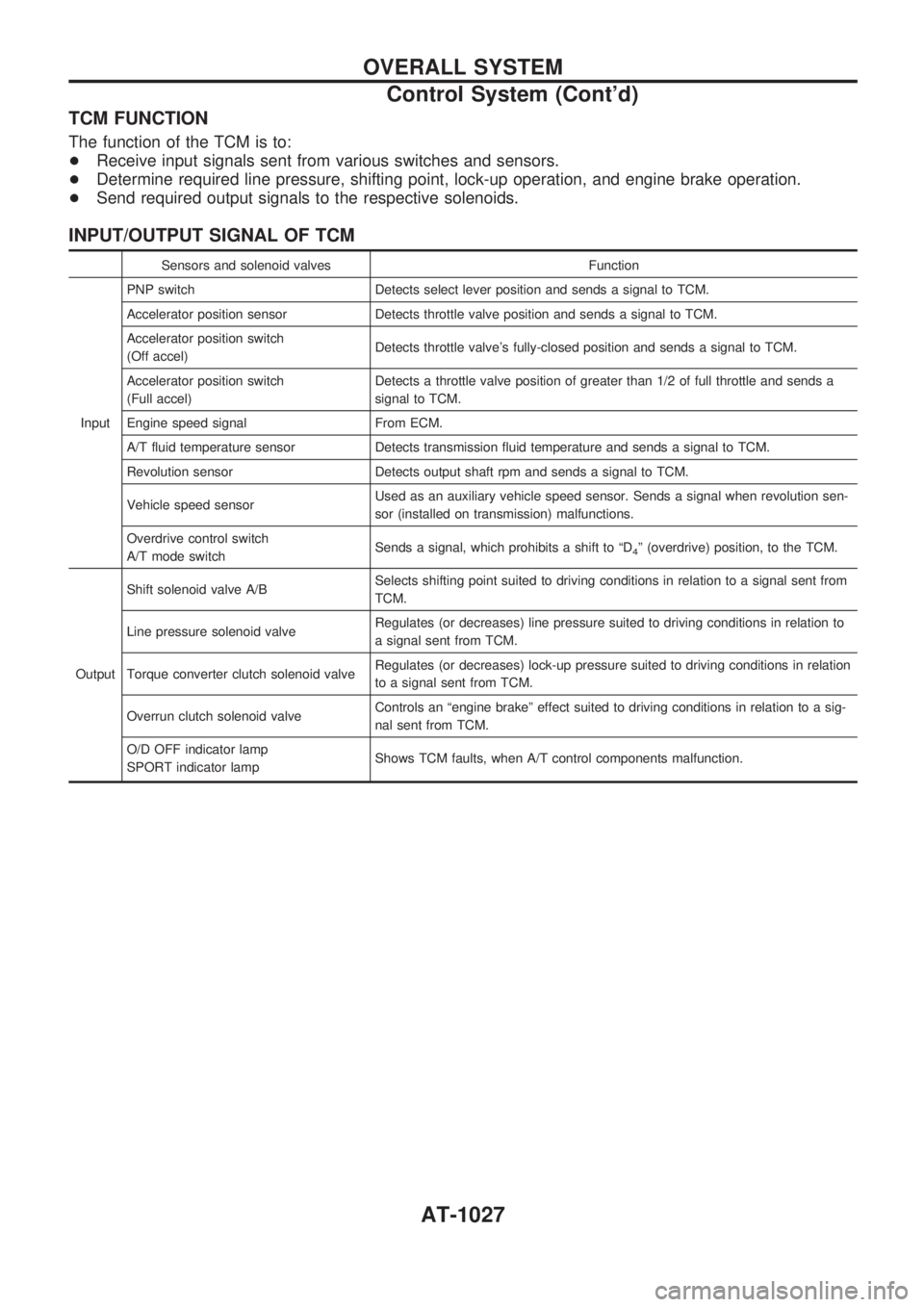
TCM FUNCTION
The function of the TCM is to:
+Receive input signals sent from various switches and sensors.
+Determine required line pressure, shifting point, lock-up operation, and engine brake operation.
+Send required output signals to the respective solenoids.
INPUT/OUTPUT SIGNAL OF TCM
Sensors and solenoid valves Function
InputPNP switch Detects select lever position and sends a signal to TCM.
Accelerator position sensor Detects throttle valve position and sends a signal to TCM.
Accelerator position switch
(Off accel)Detects throttle valve's fully-closed position and sends a signal to TCM.
Accelerator position switch
(Full accel)Detects a throttle valve position of greater than 1/2 of full throttle and sends a
signal to TCM.
Engine speed signal From ECM.
A/T fluid temperature sensor Detects transmission fluid temperature and sends a signal to TCM.
Revolution sensor Detects output shaft rpm and sends a signal to TCM.
Vehicle speed sensorUsed as an auxiliary vehicle speed sensor. Sends a signal when revolution sen-
sor (installed on transmission) malfunctions.
Overdrive control switch
A/T mode switchSends a signal, which prohibits a shift to ªD
4º (overdrive) position, to the TCM.
OutputShift solenoid valve A/BSelects shifting point suited to driving conditions in relation to a signal sent from
TCM.
Line pressure solenoid valveRegulates (or decreases) line pressure suited to driving conditions in relation to
a signal sent from TCM.
Torque converter clutch solenoid valveRegulates (or decreases) lock-up pressure suited to driving conditions in relation
to a signal sent from TCM.
Overrun clutch solenoid valveControls an ªengine brakeº effect suited to driving conditions in relation to a sig-
nal sent from TCM.
O/D OFF indicator lamp
SPORT indicator lampShows TCM faults, when A/T control components malfunction.
OVERALL SYSTEM
Control System (Cont'd)
AT-1027
Page 31 of 1033
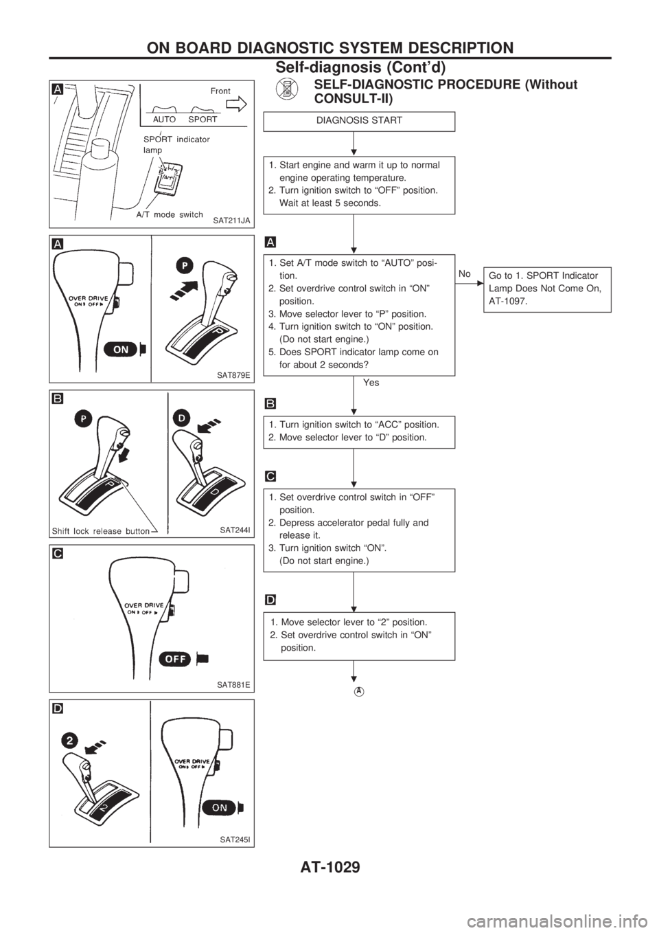
SELF-DIAGNOSTIC PROCEDURE (Without
CONSULT-II)
DIAGNOSIS START
1. Start engine and warm it up to normal
engine operating temperature.
2. Turn ignition switch to ªOFFº position.
Wait at least 5 seconds.
1. Set A/T mode switch to ªAUTOº posi-
tion.
2. Set overdrive control switch in ªONº
position.
3. Move selector lever to ªPº position.
4. Turn ignition switch to ªONº position.
(Do not start engine.)
5. Does SPORT indicator lamp come on
for about 2 seconds?
Yes
cNo
Go to 1. SPORT Indicator
Lamp Does Not Come On,
AT-1097.
1. Turn ignition switch to ªACCº position.
2. Move selector lever to ªDº position.
1. Set overdrive control switch in ªOFFº
position.
2. Depress accelerator pedal fully and
release it.
3. Turn ignition switch ªONº.
(Do not start engine.)
1. Move selector lever to ª2º position.
2. Set overdrive control switch in ªONº
position.
VA
SAT211JA
SAT879E
SAT244I
SAT881E
SAT245I
.
.
.
.
.
.
ON BOARD DIAGNOSTIC SYSTEM DESCRIPTION
Self-diagnosis (Cont'd)
AT-1029
Page 34 of 1033
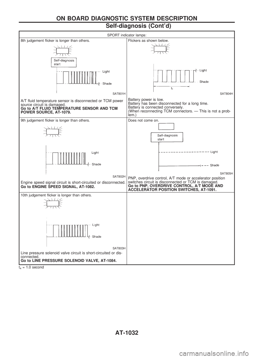
SPORT indicator lamps:
8th judgement flicker is longer than others.
SAT801H
A/T fluid temperature sensor is disconnected or TCM power
source circuit is damaged.
Go to A/T FLUID TEMPERATURE SENSOR AND TCM
POWER SOURCE, AT-1079.
Flickers as shown below.
SAT804H
Battery power is low.
Battery has been disconnected for a long time.
Battery is connected conversely.
(When reconnecting TCM connectors. Ð This is not a prob-
lem.)
9th judgement flicker is longer than others.
SAT802H
Engine speed signal circuit is short-circuited or disconnected.
Go to ENGINE SPEED SIGNAL, AT-1082.
Does not come on.
SAT805H
PNP, overdrive control, A/T mode or accelerator position
switches circuit is disconnected or TCM is damaged.
Go to PNP, OVERDRIVE CONTROL, A/T MODE AND
ACCELERATOR POSITION SWITCHES, AT-1091.
10th judgement flicker is longer than others.
SAT803H
Line pressure solenoid valve circuit is short-circuited or dis-
connected.
Go to LINE PRESSURE SOLENOID VALVE, AT-1084.
t4= 1.0 second
ON BOARD DIAGNOSTIC SYSTEM DESCRIPTION
Self-diagnosis (Cont'd)
AT-1032
Page 37 of 1033
![NISSAN PATROL 2000 Electronic Repair Manual Item DisplayMonitor item
Description Remarks TCM
input
signalsMain
signals
1 position switch 1 POSITION SW
[ON/OFF] X Ð+ON/OFF status, computed from
signal of 1 position SW, is dis-
played.
ASCD-crui NISSAN PATROL 2000 Electronic Repair Manual Item DisplayMonitor item
Description Remarks TCM
input
signalsMain
signals
1 position switch 1 POSITION SW
[ON/OFF] X Ð+ON/OFF status, computed from
signal of 1 position SW, is dis-
played.
ASCD-crui](/manual-img/5/57367/w960_57367-36.png)
Item DisplayMonitor item
Description Remarks TCM
input
signalsMain
signals
1 position switch 1 POSITION SW
[ON/OFF] X Ð+ON/OFF status, computed from
signal of 1 position SW, is dis-
played.
ASCD-cruise signal ASCD-CRUISE
[ON/OFF]
XÐ+Status of ASCD cruise signal is
displayed.
ON ... Cruising state
OFF ... Normal running state+This is displayed even when no
ASCD is mounted.
ASCD-OD cut signal ASCD-OD CUT
[ON/OFF]
XÐ+Status of ASCDzOD release
signal is displayed.
ON ... OD released
OFF ... OD not released+This is displayed even when no
ASCD is mounted.
Kickdown switch KICKDOWN SW
[ON/OFF] X Ð+ON/OFF status, computed from
signal of kickdown SW, is dis-
played.+This is displayed even when no
kickdown switch is equipped.
A/T mode switch POWER SHIFT SW
[ON/OFF] X Ð+ON/OFF state computed from
signal of POWER shift SW is
displayed.
Closed throttle position switch CLOSED THL/SW
[ON/OFF]
XÐ+ON/OFF status, computed from
signal of closed throttle (accel-
erator) position SW, is dis-
played.
Wide open throttle position switch W/O THRL/P-SW
[ON/OFF]
XÐ+ON/OFF status, computed from
signal of wide open throttle
(accelerator) position SW, is
displayed.
A/T mode switch HOLD SW
[ON/OFF] X Ð+ON/OFF status, computed from
signal of HOLD shift SW, is
displayed.
Gear position GEAR
ÐX+Gear position data used for
computation by TCM, is dis-
played.
Selector lever position SLCT LVR POSI
ÐX+Selector lever position data,
used for computation by TCM,
is displayed.+A specific value used for con-
trol is displayed if fail-safe is
activated due to error.
Vehicle speed VEHICLE SPEED
[km/h] or [mph] Ð X+Vehicle speed data, used for
computation by TCM, is dis-
played.
Accelerator position THROTTLE POSI
[/8] Ð X+Throttle (accelerator) position
data, used for computation by
TCM, is displayed.+A specific value used for con-
trol is displayed if fail-safe is
activated due to error.
Line pressure duty LINE PRES DTY
[%]
ÐX+Control value of line pressure
solenoid valve, computed by
TCM from each input signal, is
displayed.
Torque converter clutch solenoid
valve dutyTCC S/V DUTY
[%]
ÐX+Control value of torque con-
verter clutch solenoid valve,
computed by TCM from each
input signal, is displayed.
Shift solenoid valve A SHIFT S/V A
[ON/OFF]
ÐX+Control value of shift solenoid
valve A, computed by TCM
from each input signal, is dis-
played.Control value of solenoid is dis-
played even if solenoid circuit is
disconnected.
The ªOFFº signal is displayed if
solenoid circuit is shorted.
Shift solenoid valve B SHIFT S/V B
[ON/OFF]
ÐX+Control value of shift solenoid
valve B, computed by TCM
from each input signal, is dis-
played.
Overrun clutch solenoid valve OVERRUN/C S/V
[ON/OFF]
ÐX+Control value of overrun clutch
solenoid valve computed by
TCM from each input signal is
displayed.
Self-diagnosis display lamp
(SPORT indicator lamp)SELF-D DP LMP
[ON/OFF]ÐX+Control status of SPORT indi-
cator lamp is displayed.
X: Applicable
Ð: Not applicable
ON BOARD DIAGNOSTIC SYSTEM DESCRIPTION
Diagnosis by CONSULT-II (Cont'd)
AT-1035