Page 135 of 1033
1. Drain ATF through drain plug.
2. Remove torque converter by holding it firmly and turning
while pulling straight out.
3. Check torque converter one-way clutch.
a. Insert Tool into spline of one-way clutch inner race.
b. Hook bearing support unitized with one-way clutch outer race
with suitable wire.
c. Check that one-way clutch inner race rotates only clockwise
with Tool while holding bearing support with wire.
4. Remove PNP switch from transmission case.
5. Remove oil pan.
+Always place oil pan straight down so that foreign par-
ticles inside will not move.
SAT018B
SAT303B
SAT021BC
SAT754I
DISASSEMBLY
AT-1133
Page 182 of 1033
8. After installing, check to assure that forward clutch hub
rotates clockwise.
Band Servo Piston Assembly
DISASSEMBLY
1. Block one oil hole in OD servo piston retainer and the cen-
ter hole in OD band servo piston.
2. Apply compressed air to the other oil hole in piston retainer
to remove OD band servo piston from retainer.
3. Remove D-ring from OD band servo piston.
4. Remove band servo piston assembly from servo piston
retainer by pushing it forward.
SAT905A
SAT908AD
SAT909A
SAT910A
REPAIR FOR COMPONENT PARTS
Rear Internal Gear and Forward Clutch Hub
(Cont'd)
AT-1180
Page 190 of 1033
d. Install band servo retainer onto transmission case.
4. Install rear side clutch and gear components.
a. Place transmission case in vertical position.
b. Slightly lift forward clutch drum assembly. Then slowly rotate
it clockwise until its hub passes fully over clutch inner race
inside transmission case.
c. Check to be sure that rotation direction of forward clutch
assembly is correct.
d. Install thrust washer onto front of overrun clutch hub.
+Apply petroleum jelly to the thrust washer.
+Insert pawls of thrust washer securely into holes in over-
run clutch hub.
SAT940A
SAT943AA
SAT944A
SAT945A
SAT946A
ASSEMBLY
Assembly (1) (Cont'd)
AT-1188
Page 193 of 1033
b. Install needle bearing on front of front planetary carrier.
+Apply petroleum jelly to needle bearing.
c. Install needle bearing on rear of front planetary carrier.
+Apply petroleum jelly to bearing.
+Pay attention to its direction Ð Black side goes to front.
d. While rotating forward clutch drum clockwise, install front
planetary carrier on forward clutch drum.
+Check that portion A of front planetary carrier protrudes
approximately 2 mm (0.08 in) beyond portion B of for-
ward clutch assembly.
e. Install bearing races on rear of clutch pack.
+Apply petroleum jelly to bearing races.
+Securely engage pawls of bearing race with hole in
clutch pack.
f. Place transmission case in vertical position.
SAT967A
SAT969A
SAT970A
SAT204B
SAT972A
ASSEMBLY
Adjustment (Cont'd)
AT-1191
Page 199 of 1033
3. Install front side clutch and gear components.
a. Install rear sun gear on transmission case.
+Pay attention to its direction.
b. Make sure needle bearing is on front of front planetary car-
rier.
+Apply petroleum jelly to needle bearing.
c. Make sure needle bearing is on rear of front planetary car-
rier.
+Apply petroleum jelly to bearing.
+Pay attention to its direction Ð Black side goes to front.
d. While rotating forward clutch drum clockwise, install front
planetary carrier on forward clutch drum.
+Check that portion A of front planetary carrier protrudes
approximately 2 mm (0.08 in) beyond portion B of for-
ward clutch assembly.
e. Make sure bearing races are on front and rear of clutch pack.
+Apply petroleum jelly to bearing races.
+Securely engage pawls of bearing races with holes in
clutch pack.
SAT974A
SAT967A
SAT969A
SAT970A
SAT971A
ASSEMBLY
Assembly (2) (Cont'd)
AT-1197
Page 257 of 1033

Installation
+Install the injection tubes, referring to the markings made
during removal.
+Install the injection tubes in the order of No. 3, No. 4, No. 1,
and No. 2.
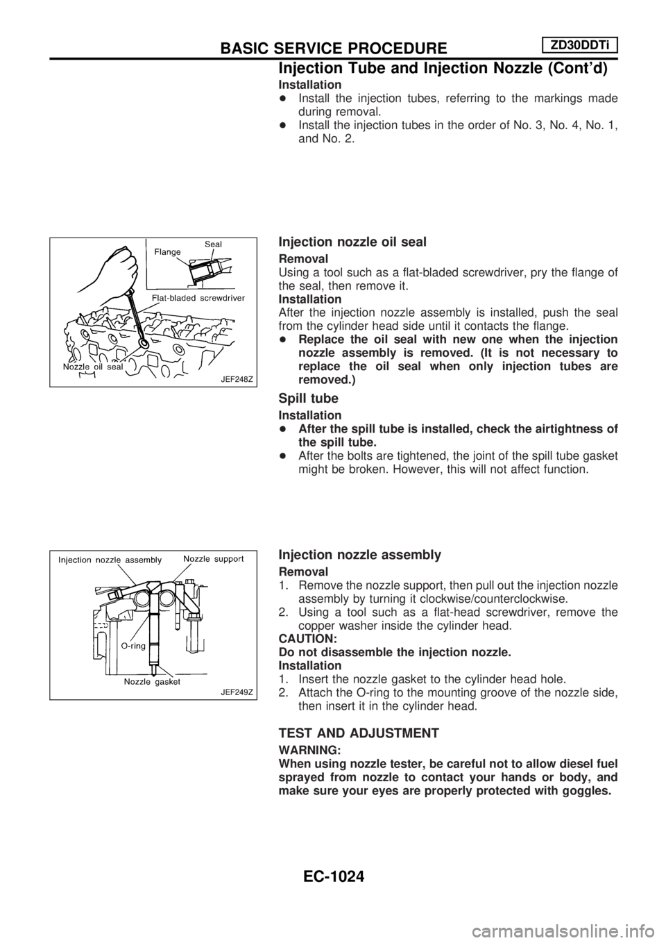
Injection nozzle oil seal
Removal
Using a tool such as a flat-bladed screwdriver, pry the flange of
the seal, then remove it.
Installation
After the injection nozzle assembly is installed, push the seal
from the cylinder head side until it contacts the flange.
+Replace the oil seal with new one when the injection
nozzle assembly is removed. (It is not necessary to
replace the oil seal when only injection tubes are
removed.)
Spill tube
Installation
+After the spill tube is installed, check the airtightness of
the spill tube.
+After the bolts are tightened, the joint of the spill tube gasket
might be broken. However, this will not affect function.
Injection nozzle assembly
Removal
1. Remove the nozzle support, then pull out the injection nozzle
assembly by turning it clockwise/counterclockwise.
2. Using a tool such as a flat-head screwdriver, remove the
copper washer inside the cylinder head.
CAUTION:
Do not disassemble the injection nozzle.
Installation
1. Insert the nozzle gasket to the cylinder head hole.
2. Attach the O-ring to the mounting groove of the nozzle side,
then insert it in the cylinder head.
TEST AND ADJUSTMENT
WARNING:
When using nozzle tester, be careful not to allow diesel fuel
sprayed from nozzle to contact your hands or body, and
make sure your eyes are properly protected with goggles.
JEF248Z
JEF249Z
BASIC SERVICE PROCEDUREZD30DDTi
Injection Tube and Injection Nozzle (Cont'd)
EC-1024
Page 260 of 1033

REMOVAL
1. Remove the following:
+Engine coolant draining
+Charge air cooler
+Air inlet pipe
+Throttle body
+Rocker cover
+Oil level gauge guide
+EGR guide tube
+EGR volume control solenoid valve
+Fuel hose
+Injection tube
+Radiator upper hose
+Radiator shroud
+Cooling fan
+Drive belt
+Vacuum pipe
+Vacuum pump
2. Move the power steering pump.
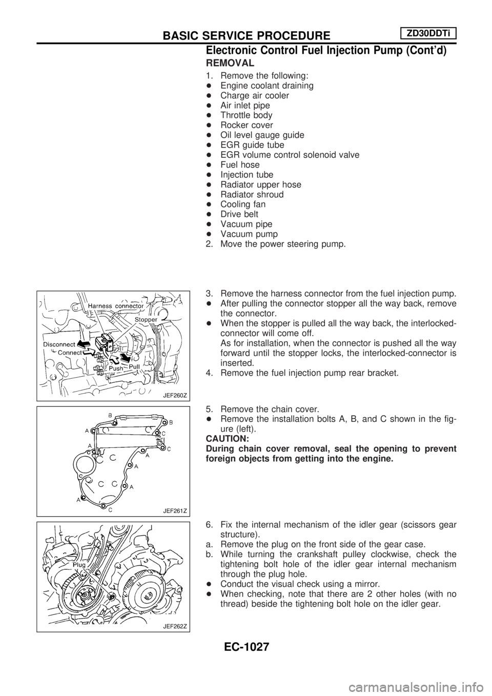
3. Remove the harness connector from the fuel injection pump.
+After pulling the connector stopper all the way back, remove
the connector.
+When the stopper is pulled all the way back, the interlocked-
connector will come off.
As for installation, when the connector is pushed all the way
forward until the stopper locks, the interlocked-connector is
inserted.
4. Remove the fuel injection pump rear bracket.
5. Remove the chain cover.
+Remove the installation bolts A, B, and C shown in the fig-
ure (left).
CAUTION:
During chain cover removal, seal the opening to prevent
foreign objects from getting into the engine.
6. Fix the internal mechanism of the idler gear (scissors gear
structure).
a. Remove the plug on the front side of the gear case.
b. While turning the crankshaft pulley clockwise, check the
tightening bolt hole of the idler gear internal mechanism
through the plug hole.
+Conduct the visual check using a mirror.
+When checking, note that there are 2 other holes (with no
thread) beside the tightening bolt hole on the idler gear.
JEF260Z
JEF261Z
JEF262Z
BASIC SERVICE PROCEDUREZD30DDTi
Electronic Control Fuel Injection Pump (Cont'd)
EC-1027
Page 766 of 1033

+Vacuum pipe
+Vacuum pump
2. Move the following parts.
+TDC sensor harness
+Power steering oil pump
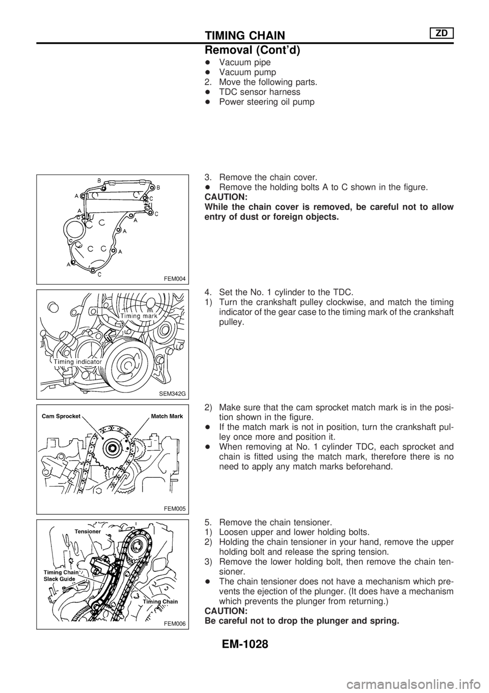
3. Remove the chain cover.
+Remove the holding bolts A to C shown in the figure.
CAUTION:
While the chain cover is removed, be careful not to allow
entry of dust or foreign objects.
4. Set the No. 1 cylinder to the TDC.
1) Turn the crankshaft pulley clockwise, and match the timing
indicator of the gear case to the timing mark of the crankshaft
pulley.
2) Make sure that the cam sprocket match mark is in the posi-
tion shown in the figure.
+If the match mark is not in position, turn the crankshaft pul-
ley once more and position it.
+When removing at No. 1 cylinder TDC, each sprocket and
chain is fitted using the match mark, therefore there is no
need to apply any match marks beforehand.
5. Remove the chain tensioner.
1) Loosen upper and lower holding bolts.
2) Holding the chain tensioner in your hand, remove the upper
holding bolt and release the spring tension.
3) Remove the lower holding bolt, then remove the chain ten-
sioner.
+The chain tensioner does not have a mechanism which pre-
vents the ejection of the plunger. (It does have a mechanism
which prevents the plunger from returning.)
CAUTION:
Be careful not to drop the plunger and spring.
FEM004
SEM342G
FEM005
FEM006
TIMING CHAINZD
Removal (Cont'd)
EM-1028