Page 753 of 1033
2. Remove catalyst.
CAUTION:
Do not disassemble catalyst.
Inspection
TURBOCHARGER
CAUTION:
When the compressor wheel, turbine wheel, or rotor shaft is
damaged, remove all the fragments and foreign matter left in the
following passages in order to prevent a secondary failure:
Suction side: Between turbocharger and intercooler
Exhaust side: Between turbocharger and catalytic
converter
Rotor shaft
+Check that the rotor shaft rotates smoothly without any resis-
tance when it is rotated by your fingertips.
+Check that the rotor shaft is not loose when it is moved ver-
tically or horizontally.
Standard value for rotor shaft oil clearance:
0.086 - 0.177 mm (0.0034 - 0.0070 in)
SEM297G
SEM298G
CATALYST AND TURBOCHARGERZD
Removal and Installation (Cont'd)
EM-1015
Page 756 of 1033
Removal and Installation
REMOVAL
1. Remove the following parts.
+Refer to ªPREPARATIVE WORKº in ªCATALYST AND
TURBOCHARGERº, EM-1014.
+Remove catalytic converter.
+Remove turbocharger.
2. Loosen nuts holding the exhaust manifold in the reverse
order of that shown in the figure.
SEM312G
SEM313G
EXHAUST MANIFOLDZD
EM-1018
Page 791 of 1033
Removal and Installation
Removal
1. Remove the following. (Refer to corresponding chapter for
detailed auxiliary work.)
+Drain coolant
+Rocker cover
+Injection tube
+Spill tube
+High pressure injection nozzle assembly
+Timing chain
+Camshaft
+Catalytic converter
+Turbocharger assembly
+Exhaust manifold
2. Remove mounting bolts of the gear case and water pump as
shown by arrows in the figure.
3. Remove oil return pipe from the rear side of cylinder head.
4. Remove intake manifold.
SEM359G
FEM054
CYLINDER HEADZD
EM-1053
Page 803 of 1033

5. Disconnect harness connectors from alternator and air com-
pressor.
6. Remove alternator.
7. After removing refrigerant, remove pipes of air compressor
and inlet/outlet.
8. Disconnect heating hose, install blank cap to hose to prevent
coolant from leaking.
9. Remove heating pipe.
10. Remove heat insulator.
11. Remove catalytic converter.
Engine room (Right)
12. Remove power steering reservoir tank from bracket, and fix
it to the vehicle with a rope.
CAUTION:
Keep the reservoir tank level when fixing to prevent oil leak.
13. Remove fuel feed and return hoses.
CAUTION:
Install blank caps immediately to avoid fuel leakage.
14. Remove all harness connectors on the engine, and move
harnesses to the side of the vehicle.
Vehicle underfloor
15. Remove starter motor.
16. Detach A/T oil cooler pipes from oil pan. (A/T model)
17. Remove rear propeller shaft.
18. Remove mounting bolts to secure the engine to transmission.
1) Remove torque converter installation bolt. (A/T model)
2) Lift transmission bottom with transmission jack, and remove
rear mount members from the vehicle.
3) Lower transmission with the jack, and remove upper mount-
ing bolts securing the engine to transmission.
4) Lift transmission with the jack, and reinstall rear mount mem-
bers to the vehicle.
5) Position the jack to the front side of transmission.
6) Remove remaining mounting bolts securing the engine to
transmission.
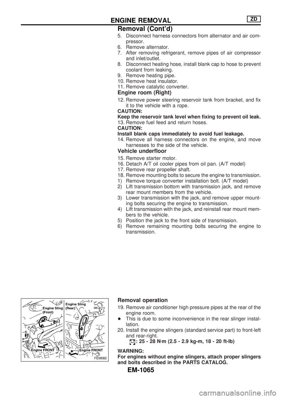
Removal operation
19. Remove air conditioner high pressure pipes at the rear of the
engine room.
+This is due to some inconvenience in the rear slinger instal-
lation.
20. Install the engine slingers (standard service part) to front-left
and rear-right.
:25-28Nzm (2.5 - 2.9 kg-m, 18 - 20 ft-lb)
WARNING:
For engines without engine slingers, attach proper slingers
and bolts described in the PARTS CATALOG.
FEM082
ENGINE REMOVALZD
Removal (Cont'd)
EM-1065
Page 807 of 1033

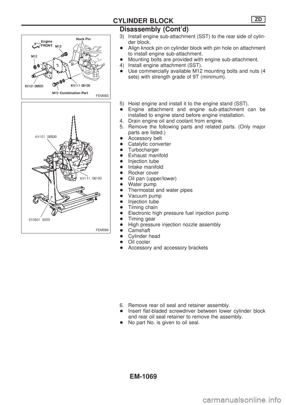
3) Install engine sub-attachment (SST) to the rear side of cylin-
der block.
+Align knock pin on cylinder block with pin hole on attachment
to install engine sub-attachment.
+Mounting bolts are provided with engine sub-attachment.
4) Install engine attachment (SST).
+Use commercially available M12 mounting bolts and nuts (4
sets) with strength grade of 9T (minimum).
5) Hoist engine and install it to the engine stand (SST).
+Engine attachment and engine sub-attachment can be
installed to engine stand before engine installation.
4. Drain engine oil and coolant from engine.
5. Remove the following parts and related parts. (Only major
parts are listed.)
+Accessory belt
+Catalytic converter
+Turbocharger
+Exhaust manifold
+Injection tube
+Intake manifold
+Rocker cover
+Oil pan (upper/lower)
+Water pump
+Thermostat and water pipes
+Vacuum pump
+Injection tube
+Timing chain
+Electronic high pressure fuel injection pump
+Timing gear
+High pressure injection nozzle assembly
+Camshaft
+Cylinder head
+Oil cooler
+Accessory and accessory brackets
6. Remove rear oil seal and retainer assembly.
+Insert flat-bladed screwdriver between lower cylinder block
and rear oil seal retainer to remove the assembly.
+No part No. is given to oil seal.
FEM083
FEM084
CYLINDER BLOCKZD
Disassembly (Cont'd)
EM-1069