2000 NISSAN PATROL brake fluid
[x] Cancel search: brake fluidPage 4 of 1033

Diagnostic Procedure....................................... 1088
TROUBLE DIAGNOSIS FOR CONTROL UNIT
(EFP ROM)........................................................... 1089
Description ....................................................... 1089
Diagnostic Procedure....................................... 1090
TROUBLE DIAGNOSIS FOR
NON-DETECTABLE ITEMS................................ 1091
PNP, Overdrive Control, A/T Mode or
Accelerator Position Switches ......................... 1091
DIAGNOSTIC PROCEDURES FOR
SYMPTOMS......................................................... 1097
1. SPORT Indicator Lamp Does Not
Come On.......................................................... 1097
2. SPORT Indicator Lamp Does Not
Come On.......................................................... 1098
3. O/D OFF Indicator Lamp Does Not Come
On .................................................................... 1098
4. SPORT Indicator Lamp Does Not
Come On.......................................................... 1099
5. Engine Cannot Be Started In ªPº and ªNº
Position ............................................................ 1100
6. In ªPº Position, Vehicle Moves Forward Or
Backward When Pushed ................................. 1100
7. In ªNº Position, Vehicle Moves .................... 1101
8. Large Shock. ªNº®ªRº Position ................ 1102
9. Vehicle Does Not Creep Backward In ªRº
Position ............................................................ 1103
10. Vehicle Does Not Creep Forward In ªDº,
ª2º Or ª1º Position ............................................ 1104
11. Vehicle Cannot Be Started From D
1......... 1105
12. A/T Does Not Shift: D
1®D2Or Does Not
Kickdown: D
4®D2......................................... 1106
13. A/T Does Not Shift: D
2®D3.................... 1107
14. A/T Does Not Shift: D
3®D4.................... 1108
15. A/T Does Not Perform Lock-up ................. 1109
16. A/T Does Not Hold Lock-up Condition ...... 1110
17. Lock-up Is Not Released ........................... 1110
18. Engine Speed Does Not Return To Idle
(Light Braking D
4®D3) .................................. 1111
19. Vehicle Does Not Start From D
1............... 1112
20. A/T Does Not Shift: D
2®D1When
Depressing Accelerator Pedal ......................... 1113
21. A/T Does Not Shift: D
4®D3, When
Overdrive Control Switch ªONº®ªOFFº ........ 1114
22. A/T Does Not Shift: D
3®22, When
Selector Lever ªDº®ª2º Position ................... 1114
23. A/T Does Not Shift: 2
2®11, WhenSelector Lever ª2º®ª1º Position .................... 1115
24. Vehicle Does Not Decelerate By Engine
Brake ................................................................ 1115
TROUBLE DIAGNOSES Ð A/T Shift Lock
System................................................................. 1116
Description ....................................................... 1116
Wiring Diagram Ð SHIFT Ð ........................... 1117
Diagnostic Procedure....................................... 1118
Key Interlock Cable.......................................... 1121
Component Check ........................................... 1122
ON-VEHICLE SERVICE...................................... 1124
Control Valve Assembly and Accumulators .... 1124
Revolution Sensor Replacement ..................... 1125
Rear Oil Seal Replacement ............................. 1125
Parking Pawl Components Inspection ............. 1125
PNP Switch Adjustment ................................... 1125
Manual Control Linkage Adjustment................ 1126
REMOVAL AND INSTALLATION....................... 1127
Removal ........................................................... 1127
Installation ........................................................ 1128
MAJOR OVERHAUL........................................... 1129
Oil Channel ...................................................... 1131
Locations of Needle Bearings, Thrust Washers
and Snap Rings ............................................... 1132
DISASSEMBLY.................................................... 1133
REPAIR FOR COMPONENT PARTS................. 1144
Oil Pump .......................................................... 1144
Control Valve Assembly................................... 1148
Control Valve Upper Body ............................... 1154
Control Valve Lower Body ............................... 1159
Reverse Clutch ................................................ 1161
High Clutch ...................................................... 1165
Forward and Overrun Clutches ....................... 1167
Low & Reverse Brake ...................................... 1171
Forward Clutch Drum Assembly ...................... 1175
Rear Internal Gear and Forward Clutch Hub .. 1177
Band Servo Piston Assembly .......................... 1180
Parking Pawl Components .............................. 1184
ASSEMBLY.......................................................... 1186
Assembly (1) .................................................... 1186
Adjustment ....................................................... 1190
Assembly (2) .................................................... 1195
A/T FLUID COOLER SYSTEM........................... 1205
A/T Fluid Cooler ............................................... 1205
SERVICE DATA AND SPECIFICATIONS (SDS)1206
General Specifications ..................................... 1206
Specifications and Adjustment......................... 1206
When you read wiring diagrams:
+Read GI section, ªHOW TO READ WIRING DIAGRAMSº.
+See EL section, ªPOWER SUPPLY ROUTINGº for power distribution circuit.
When you perform trouble diagnoses, read GI section, ªHOW TO FOLLOW FLOW
CHART IN TROUBLE DIAGNOSESº.
AT-1002
Page 29 of 1033
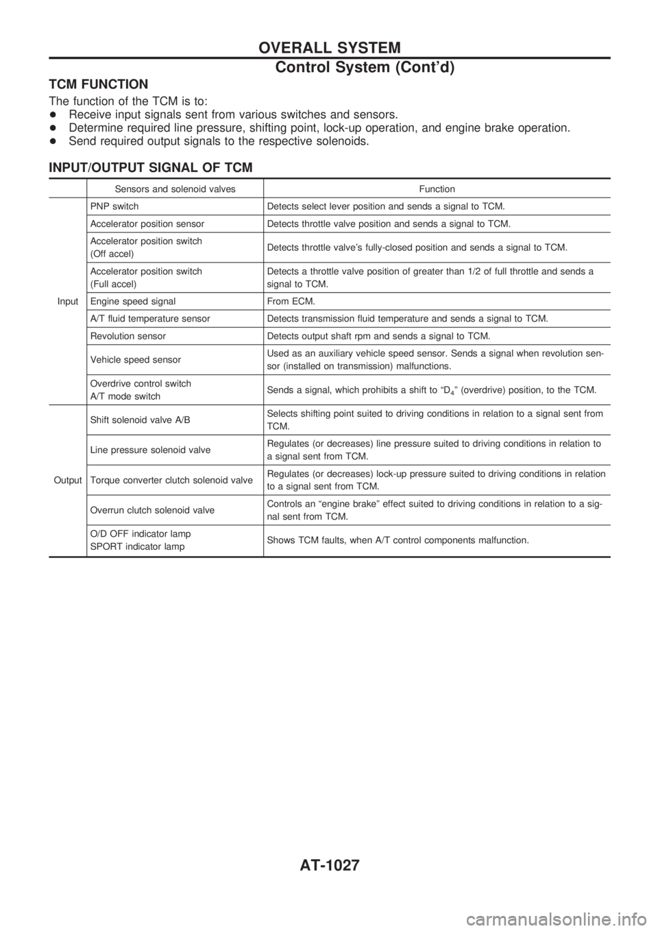
TCM FUNCTION
The function of the TCM is to:
+Receive input signals sent from various switches and sensors.
+Determine required line pressure, shifting point, lock-up operation, and engine brake operation.
+Send required output signals to the respective solenoids.
INPUT/OUTPUT SIGNAL OF TCM
Sensors and solenoid valves Function
InputPNP switch Detects select lever position and sends a signal to TCM.
Accelerator position sensor Detects throttle valve position and sends a signal to TCM.
Accelerator position switch
(Off accel)Detects throttle valve's fully-closed position and sends a signal to TCM.
Accelerator position switch
(Full accel)Detects a throttle valve position of greater than 1/2 of full throttle and sends a
signal to TCM.
Engine speed signal From ECM.
A/T fluid temperature sensor Detects transmission fluid temperature and sends a signal to TCM.
Revolution sensor Detects output shaft rpm and sends a signal to TCM.
Vehicle speed sensorUsed as an auxiliary vehicle speed sensor. Sends a signal when revolution sen-
sor (installed on transmission) malfunctions.
Overdrive control switch
A/T mode switchSends a signal, which prohibits a shift to ªD
4º (overdrive) position, to the TCM.
OutputShift solenoid valve A/BSelects shifting point suited to driving conditions in relation to a signal sent from
TCM.
Line pressure solenoid valveRegulates (or decreases) line pressure suited to driving conditions in relation to
a signal sent from TCM.
Torque converter clutch solenoid valveRegulates (or decreases) lock-up pressure suited to driving conditions in relation
to a signal sent from TCM.
Overrun clutch solenoid valveControls an ªengine brakeº effect suited to driving conditions in relation to a sig-
nal sent from TCM.
O/D OFF indicator lamp
SPORT indicator lampShows TCM faults, when A/T control components malfunction.
OVERALL SYSTEM
Control System (Cont'd)
AT-1027
Page 40 of 1033
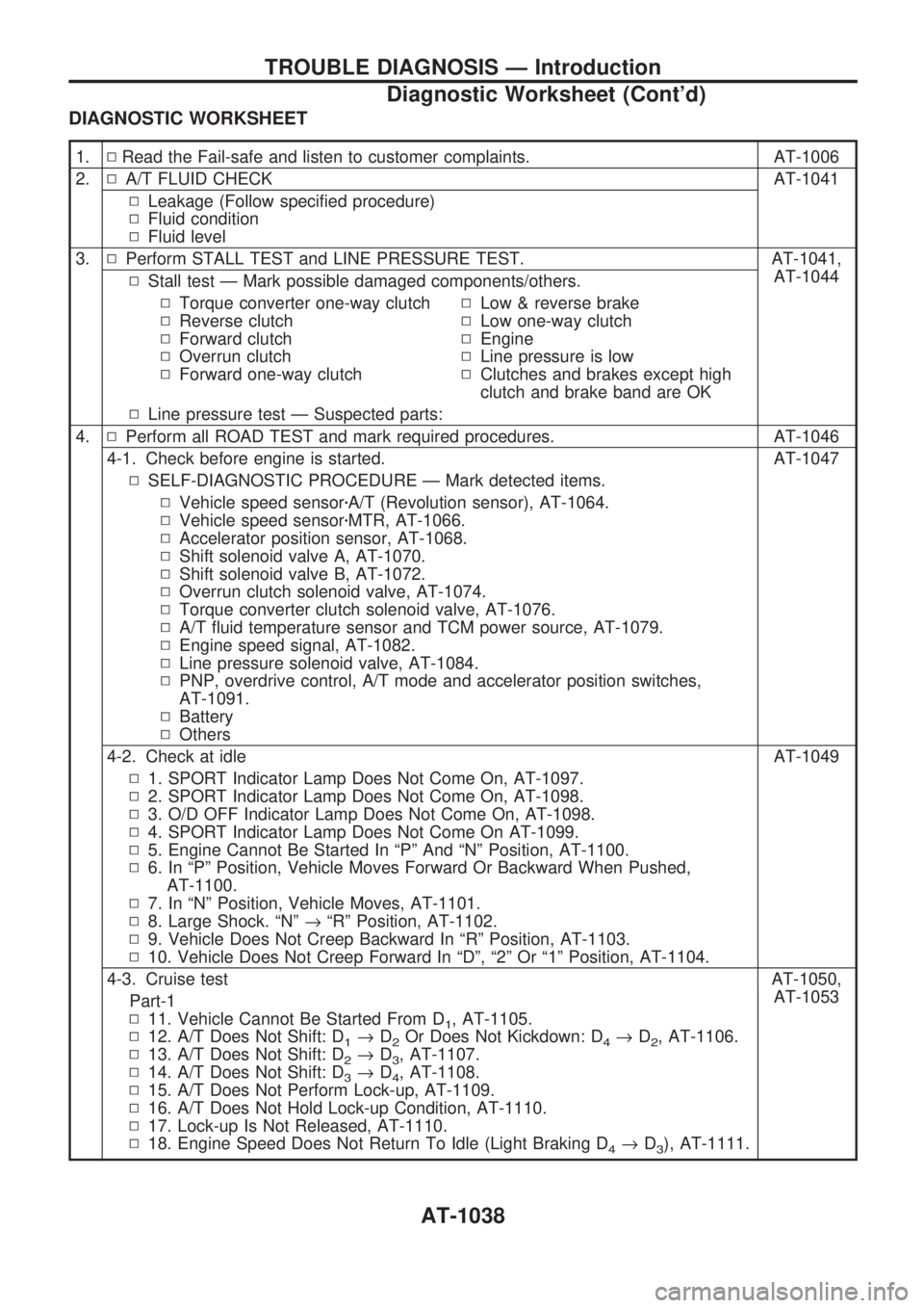
DIAGNOSTIC WORKSHEET
1.NRead the Fail-safe and listen to customer complaints. AT-1006
2.NA/T FLUID CHECK AT-1041
NLeakage (Follow specified procedure)
NFluid condition
NFluid level
3.NPerform STALL TEST and LINE PRESSURE TEST. AT-1041,
AT-1044
NStall test Ð Mark possible damaged components/others.
NTorque converter one-way clutch
NReverse clutch
NForward clutch
NOverrun clutch
NForward one-way clutchNLow & reverse brake
NLow one-way clutch
NEngine
NLine pressure is low
NClutches and brakes except high
clutch and brake band are OK
NLine pressure test Ð Suspected parts:
4.NPerform all ROAD TEST and mark required procedures. AT-1046
4-1. Check before engine is started. AT-1047
NSELF-DIAGNOSTIC PROCEDURE Ð Mark detected items.
NVehicle speed sensorzA/T (Revolution sensor), AT-1064.
NVehicle speed sensorzMTR, AT-1066.
NAccelerator position sensor, AT-1068.
NShift solenoid valve A, AT-1070.
NShift solenoid valve B, AT-1072.
NOverrun clutch solenoid valve, AT-1074.
NTorque converter clutch solenoid valve, AT-1076.
NA/T fluid temperature sensor and TCM power source, AT-1079.
NEngine speed signal, AT-1082.
NLine pressure solenoid valve, AT-1084.
NPNP, overdrive control, A/T mode and accelerator position switches,
AT-1091.
NBattery
NOthers
4-2. Check at idle AT-1049
N1. SPORT Indicator Lamp Does Not Come On, AT-1097.
N2. SPORT Indicator Lamp Does Not Come On, AT-1098.
N3. O/D OFF Indicator Lamp Does Not Come On, AT-1098.
N4. SPORT Indicator Lamp Does Not Come On AT-1099.
N5. Engine Cannot Be Started In ªPº And ªNº Position, AT-1100.
N6. In ªPº Position, Vehicle Moves Forward Or Backward When Pushed,
AT-1100.
N7. In ªNº Position, Vehicle Moves, AT-1101.
N8. Large Shock. ªNº®ªRº Position, AT-1102.
N9. Vehicle Does Not Creep Backward In ªRº Position, AT-1103.
N10. Vehicle Does Not Creep Forward In ªDº, ª2º Or ª1º Position, AT-1104.
4-3. Cruise test AT-1050,
AT-1053
Part-1
N11. Vehicle Cannot Be Started From D
1, AT-1105.
N12. A/T Does Not Shift: D
1®D2Or Does Not Kickdown: D4®D2, AT-1106.
N13. A/T Does Not Shift: D
2®D3, AT-1107.
N14. A/T Does Not Shift: D
3®D4, AT-1108.
N15. A/T Does Not Perform Lock-up, AT-1109.
N16. A/T Does Not Hold Lock-up Condition, AT-1110.
N17. Lock-up Is Not Released, AT-1110.
N18. Engine Speed Does Not Return To Idle (Light Braking D
4®D3), AT-1111.
TROUBLE DIAGNOSIS Ð Introduction
Diagnostic Worksheet (Cont'd)
AT-1038
Page 41 of 1033
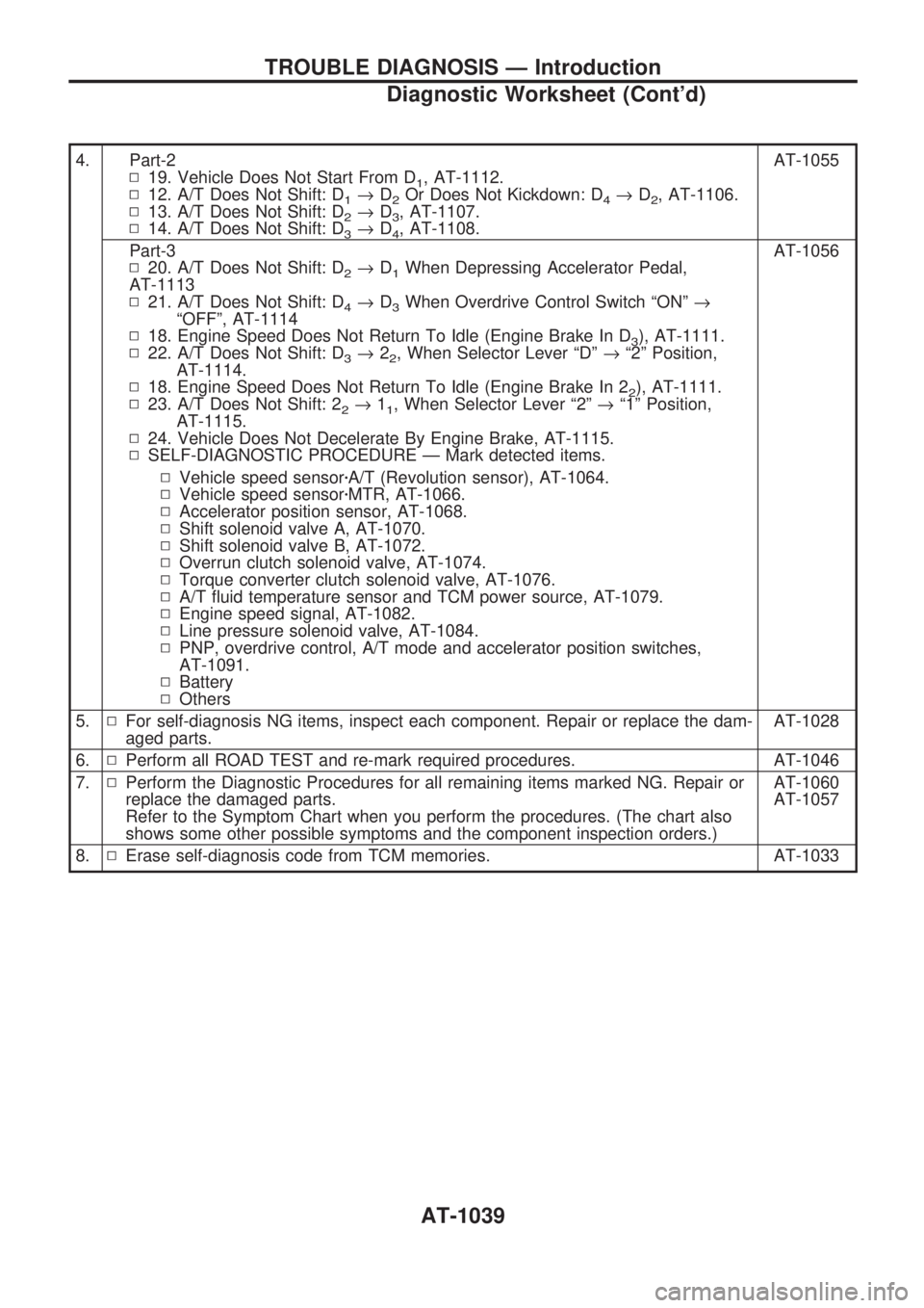
4. Part-2
N19. Vehicle Does Not Start From D
1, AT-1112.
N12. A/T Does Not Shift: D
1®D2Or Does Not Kickdown: D4®D2, AT-1106.
N13. A/T Does Not Shift: D
2®D3, AT-1107.
N14. A/T Does Not Shift: D
3®D4, AT-1108.AT-1055
Part-3
N20. A/T Does Not Shift: D
2®D1When Depressing Accelerator Pedal,
AT-1113
N21. A/T Does Not Shift: D
4®D3When Overdrive Control Switch ªONº®
ªOFFº, AT-1114
N18. Engine Speed Does Not Return To Idle (Engine Brake In D
3), AT-1111.
N22. A/T Does Not Shift: D
3®22, When Selector Lever ªDº®ª2º Position,
AT-1114.
N18. Engine Speed Does Not Return To Idle (Engine Brake In 2
2), AT-1111.
N23. A/T Does Not Shift: 2
2®11, When Selector Lever ª2º®ª1º Position,
AT-1115.
N24. Vehicle Does Not Decelerate By Engine Brake, AT-1115.
NSELF-DIAGNOSTIC PROCEDURE Ð Mark detected items.AT-1056
NVehicle speed sensorzA/T (Revolution sensor), AT-1064.
NVehicle speed sensorzMTR, AT-1066.
NAccelerator position sensor, AT-1068.
NShift solenoid valve A, AT-1070.
NShift solenoid valve B, AT-1072.
NOverrun clutch solenoid valve, AT-1074.
NTorque converter clutch solenoid valve, AT-1076.
NA/T fluid temperature sensor and TCM power source, AT-1079.
NEngine speed signal, AT-1082.
NLine pressure solenoid valve, AT-1084.
NPNP, overdrive control, A/T mode and accelerator position switches,
AT-1091.
NBattery
NOthers
5.NFor self-diagnosis NG items, inspect each component. Repair or replace the dam-
aged parts.AT-1028
6.NPerform all ROAD TEST and re-mark required procedures. AT-1046
7.NPerform the Diagnostic Procedures for all remaining items marked NG. Repair or
replace the damaged parts.
Refer to the Symptom Chart when you perform the procedures. (The chart also
shows some other possible symptoms and the component inspection orders.)AT-1060
AT-1057
8.NErase self-diagnosis code from TCM memories. AT-1033
TROUBLE DIAGNOSIS Ð Introduction
Diagnostic Worksheet (Cont'd)
AT-1039
Page 43 of 1033
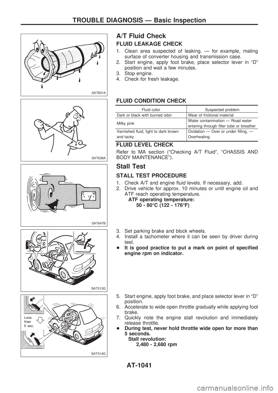
A/T Fluid Check
FLUID LEAKAGE CHECK
1. Clean area suspected of leaking. Ð for example, mating
surface of converter housing and transmission case.
2. Start engine, apply foot brake, place selector lever in ªDº
position and wait a few minutes.
3. Stop engine.
4. Check for fresh leakage.
FLUID CONDITION CHECK
Fluid color Suspected problem
Dark or black with burned odor Wear of frictional material
Milky pinkWater contamination Ð Road water
entering through filler tube or breather
Varnished fluid, light to dark brown
and tackyOxidation Ð Over or under filling, Ð
Overheating
FLUID LEVEL CHECK
Refer to MA section (ªChecking A/T Fluidº, ªCHASSIS AND
BODY MAINTENANCEº).
Stall Test
STALL TEST PROCEDURE
1. Check A/T and engine fluid levels. If necessary, add.
2. Drive vehicle for approx. 10 minutes or until engine oil and
ATF reach operating temperature.
ATF operating temperature:
50 - 80ÉC (122 - 176ÉF)
3. Set parking brake and block wheels.
4. Install a tachometer where it can be seen by driver during
test.
+It is good practice to put a mark on point of specified
engine rpm on indicator.
5. Start engine, apply foot brake, and place selector lever in ªDº
position.
6. Accelerate to wide open throttle gradually while applying foot
brake.
7. Quickly note the engine stall revolution and immediately
release throttle.
+During test, never hold throttle wide open for more than
5 seconds.
Stall revolution:
2,480 - 2,680 rpm
SAT801A
SAT638A
SAT647B
SAT513G
SAT514G
TROUBLE DIAGNOSIS Ð Basic Inspection
AT-1041
Page 44 of 1033
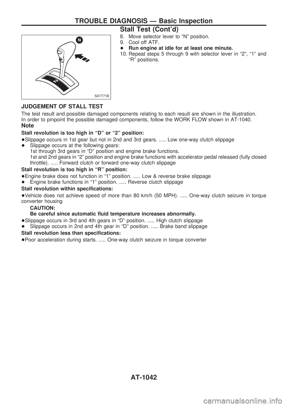
8. Move selector lever to ªNº position.
9. Cool off ATF.
+Run engine at idle for at least one minute.
10. Repeat steps 5 through 9 with selector lever in ª2º, ª1º and
ªRº positions.
JUDGEMENT OF STALL TEST
The test result and possible damaged components relating to each result are shown in the illustration.
In order to pinpoint the possible damaged components, follow the WORK FLOW shown in AT-1040.
Note
Stall revolution is too high in ªDº or ª2º position:
+Slippage occurs in 1st gear but not in 2nd and 3rd gears. ..... Low one-way clutch slippage
+Slippage occurs at the following gears:
1st through 3rd gears in ªDº position and engine brake functions.
1st and 2nd gears in ª2º position and engine brake functions with accelerator pedal released (fully closed
throttle). ..... Forward clutch or forward one-way clutch slippage
Stall revolution is too high in ªRº position:
+Engine brake does not function in ª1º position. ..... Low & reverse brake slippage
+Engine brake functions in ª1º position. ..... Reverse clutch slippage
Stall revolution within specifications:
+Vehicle does not achieve speed of more than 80 km/h (50 MPH). ..... One-way clutch seizure in torque
converter housing
CAUTION:
Be careful since automatic fluid temperature increases abnormally.
+Slippage occurs in 3rd and 4th gears in ªDº position. ..... High clutch slippage
+Slippage occurs in 2nd and 4th gear in ªDº position. ..... Brake band slippage
Stall revolution less than specifications:
+Poor acceleration during starts. ..... One-way clutch seizure in torque converter
SAT771B
TROUBLE DIAGNOSIS Ð Basic Inspection
Stall Test (Cont'd)
AT-1042
Page 47 of 1033
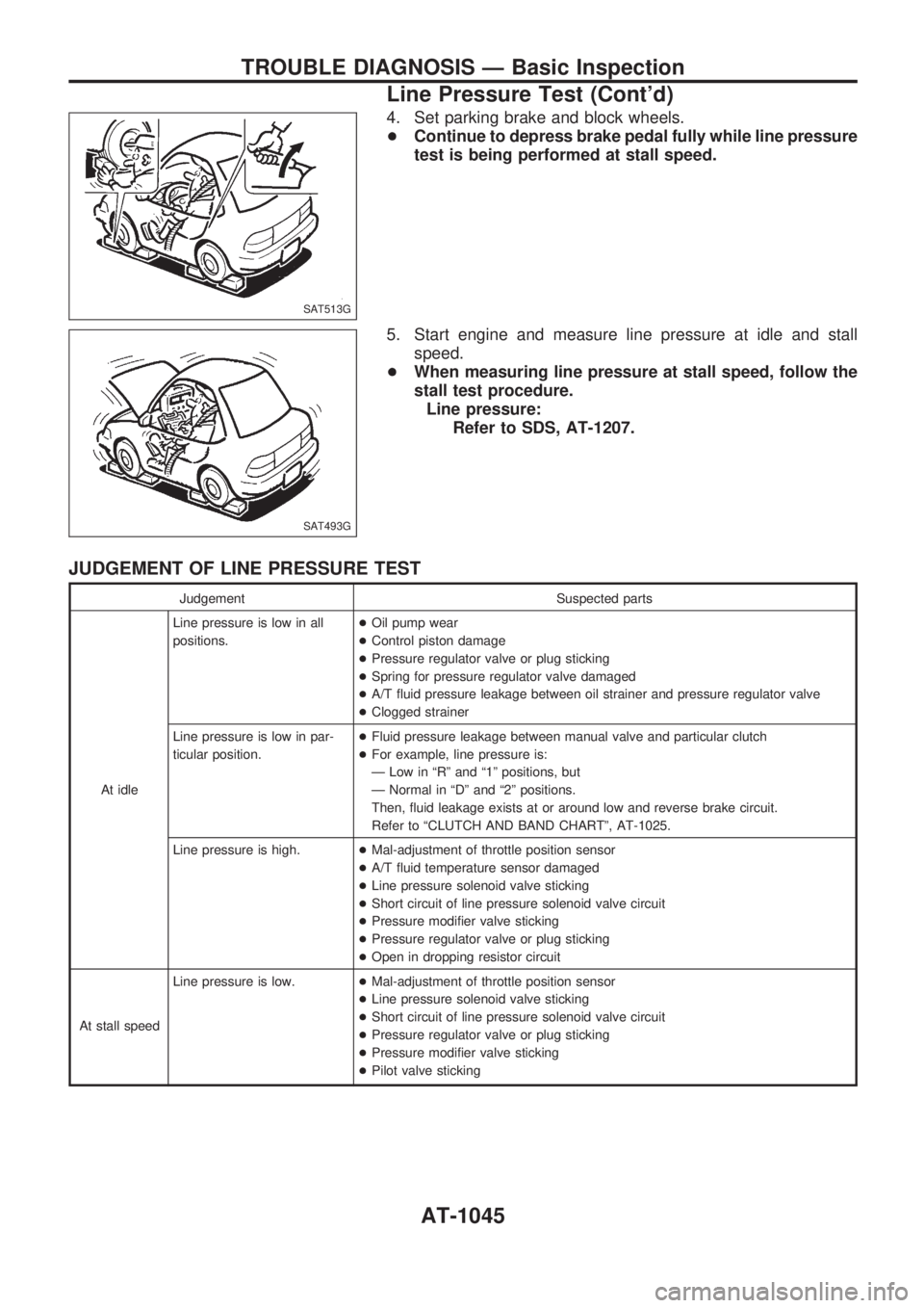
4. Set parking brake and block wheels.
+Continue to depress brake pedal fully while line pressure
test is being performed at stall speed.
5. Start engine and measure line pressure at idle and stall
speed.
+When measuring line pressure at stall speed, follow the
stall test procedure.
Line pressure:
Refer to SDS, AT-1207.
JUDGEMENT OF LINE PRESSURE TEST
Judgement Suspected parts
At idleLine pressure is low in all
positions.+Oil pump wear
+Control piston damage
+Pressure regulator valve or plug sticking
+Spring for pressure regulator valve damaged
+A/T fluid pressure leakage between oil strainer and pressure regulator valve
+Clogged strainer
Line pressure is low in par-
ticular position.+Fluid pressure leakage between manual valve and particular clutch
+For example, line pressure is:
Ð Low in ªRº and ª1º positions, but
Ð Normal in ªDº and ª2º positions.
Then, fluid leakage exists at or around low and reverse brake circuit.
Refer to ªCLUTCH AND BAND CHARTº, AT-1025.
Line pressure is high.+Mal-adjustment of throttle position sensor
+A/T fluid temperature sensor damaged
+Line pressure solenoid valve sticking
+Short circuit of line pressure solenoid valve circuit
+Pressure modifier valve sticking
+Pressure regulator valve or plug sticking
+Open in dropping resistor circuit
At stall speedLine pressure is low.+Mal-adjustment of throttle position sensor
+Line pressure solenoid valve sticking
+Short circuit of line pressure solenoid valve circuit
+Pressure regulator valve or plug sticking
+Pressure modifier valve sticking
+Pilot valve sticking
SAT513G
SAT493G
TROUBLE DIAGNOSIS Ð Basic Inspection
Line Pressure Test (Cont'd)
AT-1045
Page 59 of 1033
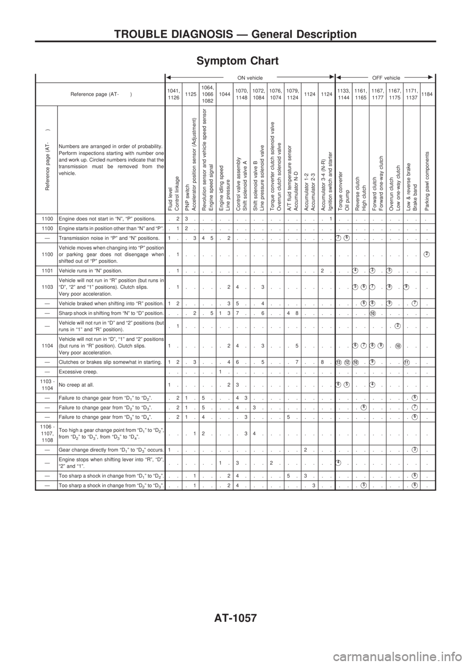
Symptom Chart
bON vehiclecbOFF vehiclec
Reference page (AT- )1041,
112611251064,
1066
108210441070,
11481072,
10841076,
10741079,
11241124 11241133,
11441161,
11651167,
11771167,
11751171,
11371184
Reference page (AT- )
Numbers are arranged in order of probability.
Perform inspections starting with number one
and work up. Circled numbers indicate that the
transmission must be removed from the
vehicle.
Fluid level
Control linkage
PNP switch
Accelerator position sensor (Adjustment)
Revolution sensor and vehicle speed sensor
Engine speed signal
Engine idling speed
Line pressure
Control valve assembly
Shift solenoid valve A
Shift solenoid valve B
Line pressure solenoid valve
Torque converter clutch solenoid valve
Overrun clutch solenoid valve
A/T fluid temperature sensor
Accumulator N-D
Accumulator 1-2
Accumulator 2-3
Accumulator 3-4 (N-R)
Ignition switch and starter
Torque converter
Oil pump
Reverse clutch
High clutch
Forward clutch
Forward one-way clutch
Overrun clutch
Low one-way clutch
Low & reverse brake
Brake band
Parking pawl components
1100 Engine does not start in ªNº, ªPº positions. . 2 3................1.......... .
1100 Engine starts in position other than ªNº and ªPº. . 1 2........................... .
Ð Transmission noise in ªPº and ªNº positions. 1 . . 3 45.2............
V7V6........ .
1100Vehicle moves when changing into ªPº position
or parking gear does not disengage when
shifted out of ªPº position..1............................
V2
1101 Vehicle runs in ªNº position. . 1................2...V4.V3.V5... .
1103Vehicle will not run in ªRº position (but runs in
ªDº, ª2º and ª1º positions). Clutch slips.
Very poor acceleration..1.....24..3..........
V5V6V7.V8.V9..
Ð Vehicle braked when shifting into ªRº position. 1 2.....35..4...........
V6V8.V9..V7.
Ð Sharp shock in shifting from ªNº to ªDº position. . .. 2 . 5137 . . 6 . . 48........
V10..... .
ÐVehicle will not run in ªDº and ª2º positions (but
runs in ª1º and ªRº position)..1.........................
V2.. .
1104Vehicle will not run in ªDº, ª1º and ª2º positions
(but runs in ªRº position). Clutch slips.
Very poor acceleration.1......24..3...5......
V6V7V8V9.V10.. .
Ð Clutches or brakes slip somewhat in starting. 12.3. . .46. .5. . .7. .8.
V13V12V10.V9...V11..
Ð Excessive creep.......1....................... .
1103 -
1104No creep at all. 1......23...........
V6V5..V4..... .
Ð Failure to change gear from ªD
1ºtoªD2º. .21.5...43...................V6.
Ð Failure to change gear from ªD
2ºtoªD3º. .21.5. . .4.3............V6.....V7.
Ð Failure to change gear from ªD
3ºtoªD4º. .21.4....3....5..............V6.
1106 -
1107,
1108Too high a gear change point from ªD
1ºtoªD2º,
from ªD2ºtoªD3º, from ªD3ºtoªD4º....12....34................... .
Ð Gear change directly from ªD
1ºtoªD3º occurs. 1...............2............V3.
ÐEngine stops when shifting lever into ªRº, ªDº,
ª2º and ª1º.......1.3. . .2.......
V4......... .
Ð Too sharp a shock in change from ªD
1ºtoªD2º....1...24.....5.3............V6.
Ð Too sharp a shock in change from ªD
2ºtoªD3º....1...24........3.....V5.....V6.
TROUBLE DIAGNOSIS Ð General Description
AT-1057