2000 NISSAN PATROL display
[x] Cancel search: displayPage 30 of 1033
Self-diagnosis
After performing this procedure, place check marks for results on
the ªDIAGNOSTIC WORKSHEETº, AT-1038. Reference pages
are provided following the items.
SELF-DIAGNOSTIC PROCEDURE (With
CONSULT-II)
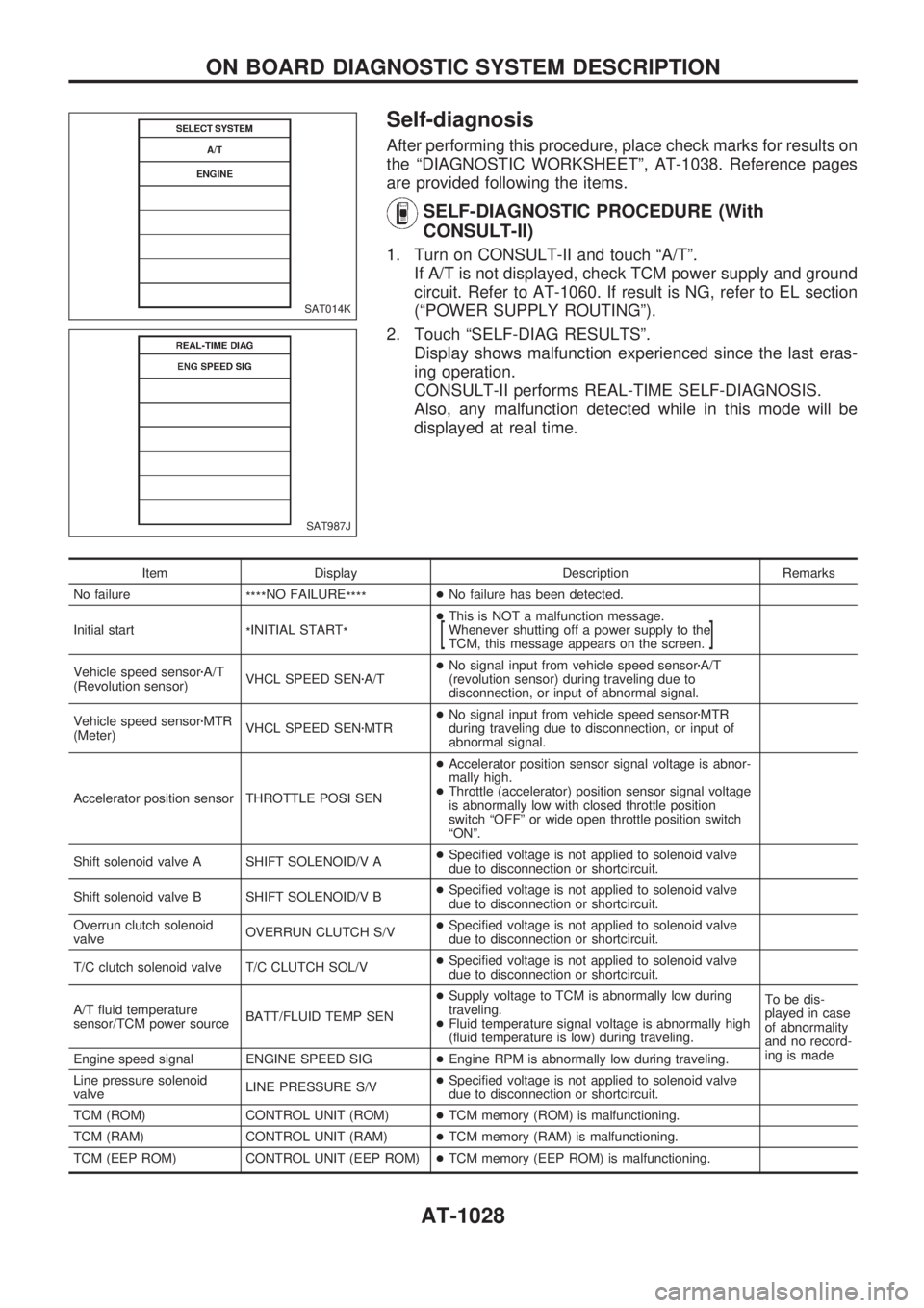
1. Turn on CONSULT-II and touch ªA/Tº.
If A/T is not displayed, check TCM power supply and ground
circuit. Refer to AT-1060. If result is NG, refer to EL section
(ªPOWER SUPPLY ROUTINGº).
2. Touch ªSELF-DIAG RESULTSº.
Display shows malfunction experienced since the last eras-
ing operation.
CONSULT-II performs REAL-TIME SELF-DIAGNOSIS.
Also, any malfunction detected while in this mode will be
displayed at real time.
Item Display Description Remarks
No failure
****NO FAILURE
****+No failure has been detected.
Initial start
*INITIAL START
*+This is NOT a malfunction message.
Whenever shutting off a power supply to the
TCM, this message appears on the screen.
[]
Vehicle speed sensorzA/T
(Revolution sensor)VHCL SPEED SENzA/T+No signal input from vehicle speed sensorzA/T
(revolution sensor) during traveling due to
disconnection, or input of abnormal signal.
Vehicle speed sensorzMTR
(Meter)VHCL SPEED SENzMTR+No signal input from vehicle speed sensorzMTR
during traveling due to disconnection, or input of
abnormal signal.
Accelerator position sensor THROTTLE POSI SEN+Accelerator position sensor signal voltage is abnor-
mally high.
+Throttle (accelerator) position sensor signal voltage
is abnormally low with closed throttle position
switch ªOFFº or wide open throttle position switch
ªONº.
Shift solenoid valve A SHIFT SOLENOID/V A+Specified voltage is not applied to solenoid valve
due to disconnection or shortcircuit.
Shift solenoid valve B SHIFT SOLENOID/V B+Specified voltage is not applied to solenoid valve
due to disconnection or shortcircuit.
Overrun clutch solenoid
valveOVERRUN CLUTCH S/V+Specified voltage is not applied to solenoid valve
due to disconnection or shortcircuit.
T/C clutch solenoid valve T/C CLUTCH SOL/V+Specified voltage is not applied to solenoid valve
due to disconnection or shortcircuit.
A/T fluid temperature
sensor/TCM power sourceBATT/FLUID TEMP SEN+Supply voltage to TCM is abnormally low during
traveling.
+Fluid temperature signal voltage is abnormally high
(fluid temperature is low) during traveling.To be dis-
played in case
of abnormality
and no record-
ing is made
Engine speed signal ENGINE SPEED SIG+Engine RPM is abnormally low during traveling.
Line pressure solenoid
valveLINE PRESSURE S/V+Specified voltage is not applied to solenoid valve
due to disconnection or shortcircuit.
TCM (ROM) CONTROL UNIT (ROM)+TCM memory (ROM) is malfunctioning.
TCM (RAM) CONTROL UNIT (RAM)+TCM memory (RAM) is malfunctioning.
TCM (EEP ROM) CONTROL UNIT (EEP ROM)+TCM memory (EEP ROM) is malfunctioning.
SAT014K
SAT987J
ON BOARD DIAGNOSTIC SYSTEM DESCRIPTION
AT-1028
Page 36 of 1033
Diagnosis by CONSULT-II
NOTICE
1.The CONSULT-II electrically displays shift timing and lock-up timing (that is, operation timing of each
solenoid).
Check for time difference between actual shift timing and the CONSULT-II display. If the difference is
noticeable, mechanical parts (except solenoids, sensors, etc.) may be malfunctioning. Check mechanical
parts using applicable diagnostic procedures.
2. Shift schedule (which implies gear position) displayed on CONSULT-II and that indicated in Service
Manual may differ slightly. This occurs because of the following reasons:
+Actual shift schedule has more or less tolerance or allowance,
+Shift schedule indicated in Service Manual refers to the point where shifts start. Gear position dis-
played on CONSULT-II indicates the point where shifts are completed.
3. Shift solenoid valve ªAº or ªBº is displayed on CONSULT-II at the start of shifting. Gear position is dis-
played upon completion of shifting (which is computed by TCM).
4. Additional CONSULT-II information can be found in the Operation Manual supplied with the CONSULT-II
unit.
SELF-DIAGNOSTIC RESULT TEST MODE
Refer to AT-1028.
DATA MONITOR DIAGNOSTIC TEST MODE
Item DisplayMonitor item
Description Remarks TCM
input
signalsMain
signals
Vehicle speed sensor 1 (A/T)
(Revolution sensor)VHCL/S SEzA/T
[km/h] or [mph]
XÐ+Vehicle speed computed from
signal of revolution sensor is
displayed.When racing engine in ªNº or ªPº
position with vehicle stationary,
CONSULT data may not indicate
0 km/h (0 MPH).
Vehicle speed sensor 2
(Meter)VHCL/S SEzMTR
[km/h] or [mph]
XÐ+Vehicle speed computed from
signal of vehicle speed sensor
is displayed.Vehicle speed display may not be
accurate under approx. 10 km/h
(6 MPH). It may not indicate 0
km/h (0 MPH) when vehicle is
stationary.
Accelerator position sensor THRTL POS SEN
[V]XÐ+Accelerator position sensor sig-
nal voltage is displayed.
A/T fluid temperature sensor FLUID TEMP SE
[V]
XÐ+A/T fluid temperature sensor
signal voltage is displayed.
+Signal voltage lowers as fluid
temperature rises.
Battery voltage BATTERY VOLT
[V]XÐ+Source voltage of TCM is dis-
played.
Engine speed ENGINE SPEED
[rpm]
XX+Engine speed, computed from
engine speed signal, is dis-
played.Engine speed display may not be
accurate under approx. 800 rpm.
It may not indicate 0 rpm even
when engine is not running.
Overdrive control switch OVERDRIVE SW
[ON/OFF] X Ð+ON/OFF state computed from
signal of overdrive control SW
is displayed.
P/N position switch PN POSI SW
[ON/OFF] X Ð+ON/OFF state computed from
signal of PN position SW is dis-
played.
R position switch R POSITION SW
[ON/OFF] X Ð+ON/OFF state computed from
signal of R position SW is dis-
played.
D position switch D POSITION SW
[ON/OFF] X Ð+ON/OFF state computed from
signal of D position SW is dis-
played.
2 position switch 2 POSITION SW
[ON/OFF] X Ð+ON/OFF status, computed from
signal of 2 position SW, is dis-
played.
ON BOARD DIAGNOSTIC SYSTEM DESCRIPTION
AT-1034
Page 37 of 1033
![NISSAN PATROL 2000 Electronic Repair Manual Item DisplayMonitor item
Description Remarks TCM
input
signalsMain
signals
1 position switch 1 POSITION SW
[ON/OFF] X Ð+ON/OFF status, computed from
signal of 1 position SW, is dis-
played.
ASCD-crui NISSAN PATROL 2000 Electronic Repair Manual Item DisplayMonitor item
Description Remarks TCM
input
signalsMain
signals
1 position switch 1 POSITION SW
[ON/OFF] X Ð+ON/OFF status, computed from
signal of 1 position SW, is dis-
played.
ASCD-crui](/manual-img/5/57367/w960_57367-36.png)
Item DisplayMonitor item
Description Remarks TCM
input
signalsMain
signals
1 position switch 1 POSITION SW
[ON/OFF] X Ð+ON/OFF status, computed from
signal of 1 position SW, is dis-
played.
ASCD-cruise signal ASCD-CRUISE
[ON/OFF]
XÐ+Status of ASCD cruise signal is
displayed.
ON ... Cruising state
OFF ... Normal running state+This is displayed even when no
ASCD is mounted.
ASCD-OD cut signal ASCD-OD CUT
[ON/OFF]
XÐ+Status of ASCDzOD release
signal is displayed.
ON ... OD released
OFF ... OD not released+This is displayed even when no
ASCD is mounted.
Kickdown switch KICKDOWN SW
[ON/OFF] X Ð+ON/OFF status, computed from
signal of kickdown SW, is dis-
played.+This is displayed even when no
kickdown switch is equipped.
A/T mode switch POWER SHIFT SW
[ON/OFF] X Ð+ON/OFF state computed from
signal of POWER shift SW is
displayed.
Closed throttle position switch CLOSED THL/SW
[ON/OFF]
XÐ+ON/OFF status, computed from
signal of closed throttle (accel-
erator) position SW, is dis-
played.
Wide open throttle position switch W/O THRL/P-SW
[ON/OFF]
XÐ+ON/OFF status, computed from
signal of wide open throttle
(accelerator) position SW, is
displayed.
A/T mode switch HOLD SW
[ON/OFF] X Ð+ON/OFF status, computed from
signal of HOLD shift SW, is
displayed.
Gear position GEAR
ÐX+Gear position data used for
computation by TCM, is dis-
played.
Selector lever position SLCT LVR POSI
ÐX+Selector lever position data,
used for computation by TCM,
is displayed.+A specific value used for con-
trol is displayed if fail-safe is
activated due to error.
Vehicle speed VEHICLE SPEED
[km/h] or [mph] Ð X+Vehicle speed data, used for
computation by TCM, is dis-
played.
Accelerator position THROTTLE POSI
[/8] Ð X+Throttle (accelerator) position
data, used for computation by
TCM, is displayed.+A specific value used for con-
trol is displayed if fail-safe is
activated due to error.
Line pressure duty LINE PRES DTY
[%]
ÐX+Control value of line pressure
solenoid valve, computed by
TCM from each input signal, is
displayed.
Torque converter clutch solenoid
valve dutyTCC S/V DUTY
[%]
ÐX+Control value of torque con-
verter clutch solenoid valve,
computed by TCM from each
input signal, is displayed.
Shift solenoid valve A SHIFT S/V A
[ON/OFF]
ÐX+Control value of shift solenoid
valve A, computed by TCM
from each input signal, is dis-
played.Control value of solenoid is dis-
played even if solenoid circuit is
disconnected.
The ªOFFº signal is displayed if
solenoid circuit is shorted.
Shift solenoid valve B SHIFT S/V B
[ON/OFF]
ÐX+Control value of shift solenoid
valve B, computed by TCM
from each input signal, is dis-
played.
Overrun clutch solenoid valve OVERRUN/C S/V
[ON/OFF]
ÐX+Control value of overrun clutch
solenoid valve computed by
TCM from each input signal is
displayed.
Self-diagnosis display lamp
(SPORT indicator lamp)SELF-D DP LMP
[ON/OFF]ÐX+Control status of SPORT indi-
cator lamp is displayed.
X: Applicable
Ð: Not applicable
ON BOARD DIAGNOSTIC SYSTEM DESCRIPTION
Diagnosis by CONSULT-II (Cont'd)
AT-1035
Page 53 of 1033
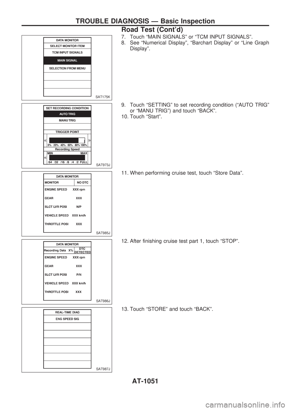
7. Touch ªMAIN SIGNALSº or ªTCM INPUT SIGNALSº.
8. See ªNumerical Displayº, ªBarchart Displayº or ªLine Graph
Displayº.
9. Touch ªSETTINGº to set recording condition (ªAUTO TRIGº
or ªMANU TRIGº) and touch ªBACKº.
10. Touch ªStartº.
11. When performing cruise test, touch ªStore Dataº.
12. After finishing cruise test part 1, touch ªSTOPº.
13. Touch ªSTOREº and touch ªBACKº.
SAT175K
SAT973J
SAT985J
SAT986J
SAT987J
TROUBLE DIAGNOSIS Ð Basic Inspection
Road Test (Cont'd)
AT-1051
Page 54 of 1033
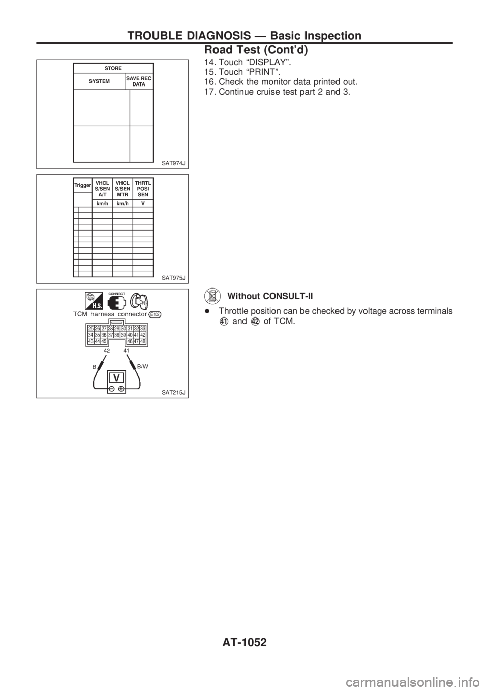
14. Touch ªDISPLAYº.
15. Touch ªPRINTº.
16. Check the monitor data printed out.
17. Continue cruise test part 2 and 3.
Without CONSULT-II
+Throttle position can be checked by voltage across terminals
V41andV42of TCM.
SAT974J
SAT975J
SAT215J
TROUBLE DIAGNOSIS Ð Basic Inspection
Road Test (Cont'd)
AT-1052
Page 90 of 1033
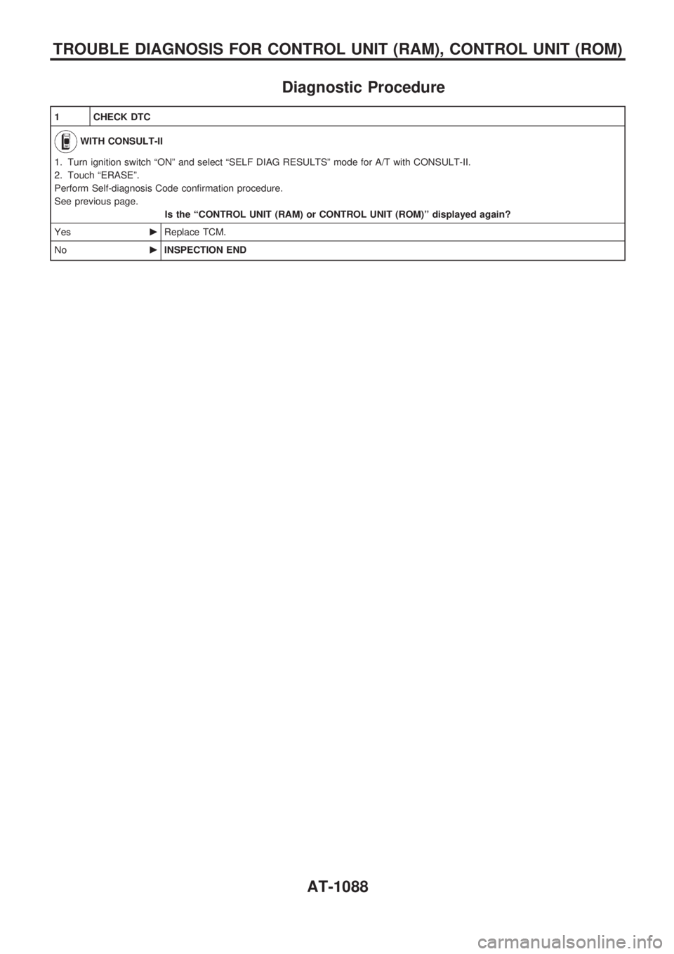
Diagnostic Procedure
1 CHECK DTC
WITH CONSULT-II
1. Turn ignition switch ªONº and select ªSELF DIAG RESULTSº mode for A/T with CONSULT-II.
2. Touch ªERASEº.
Perform Self-diagnosis Code confirmation procedure.
See previous page.
Is the ªCONTROL UNIT (RAM) or CONTROL UNIT (ROM)º displayed again?
YescReplace TCM.
NocINSPECTION END
TROUBLE DIAGNOSIS FOR CONTROL UNIT (RAM), CONTROL UNIT (ROM)
AT-1088
Page 92 of 1033
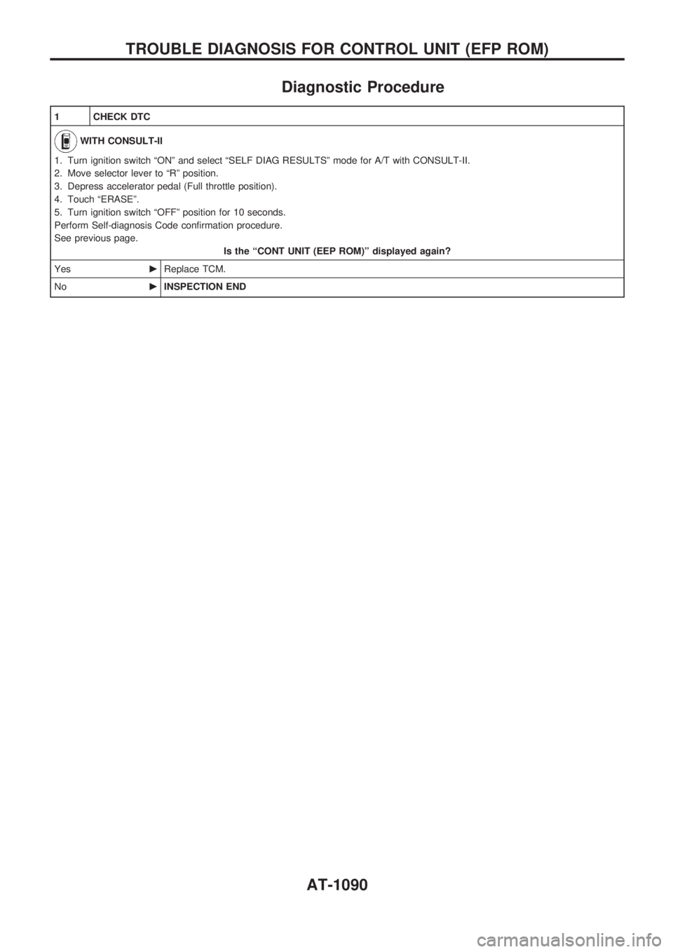
Diagnostic Procedure
1 CHECK DTC
WITH CONSULT-II
1. Turn ignition switch ªONº and select ªSELF DIAG RESULTSº mode for A/T with CONSULT-II.
2. Move selector lever to ªRº position.
3. Depress accelerator pedal (Full throttle position).
4. Touch ªERASEº.
5. Turn ignition switch ªOFFº position for 10 seconds.
Perform Self-diagnosis Code confirmation procedure.
See previous page.
Is the ªCONT UNIT (EEP ROM)º displayed again?
YescReplace TCM.
NocINSPECTION END
TROUBLE DIAGNOSIS FOR CONTROL UNIT (EFP ROM)
AT-1090
Page 95 of 1033
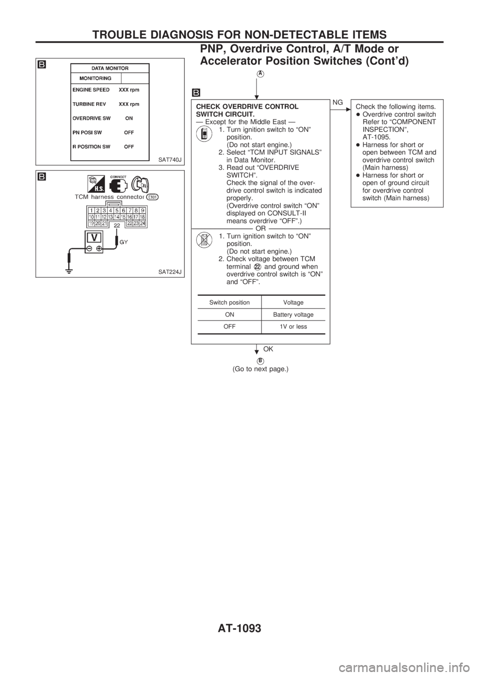
VA
CHECK OVERDRIVE CONTROL
SWITCH CIRCUIT.
Ð Except for the Middle East Ð
1. Turn ignition switch to ªONº
position.
(Do not start engine.)
2. Select ªTCM INPUT SIGNALSº
in Data Monitor.
3. Read out ªOVERDRIVE
SWITCHº.
Check the signal of the over-
drive control switch is indicated
properly.
(Overdrive control switch ªONº
displayed on CONSULT-II
means overdrive ªOFFº.)
------------------------------------------------------------------------------------------------------------------------------------OR------------------------------------------------------------------------------------------------------------------------------------
1. Turn ignition switch to ªONº
position.
(Do not start engine.)
2. Check voltage between TCM
terminal
V22and ground when
overdrive control switch is ªONº
and ªOFFº.
OK
cNG
Check the following items.
+Overdrive control switch
Refer to ªCOMPONENT
INSPECTIONº,
AT-1095.
+Harness for short or
open between TCM and
overdrive control switch
(Main harness)
+Harness for short or
open of ground circuit
for overdrive control
switch (Main harness)
VB
(Go to next page.)
Switch position Voltage
ON Battery voltage
OFF 1V or less
SAT740J
SAT224J
.
.
TROUBLE DIAGNOSIS FOR NON-DETECTABLE ITEMS
PNP, Overdrive Control, A/T Mode or
Accelerator Position Switches (Cont'd)
AT-1093