2000 NISSAN PATROL display
[x] Cancel search: displayPage 242 of 1033
tion due to receiving external noise, degraded operation
of ICs, etc.
+Keep ECM parts and harnesses dry.
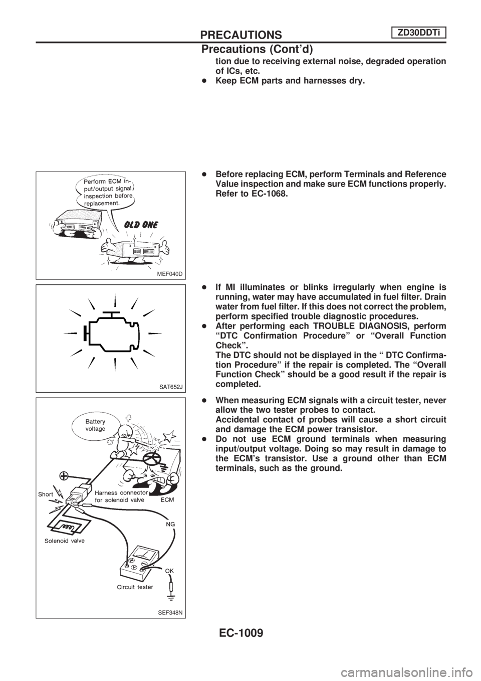
+Before replacing ECM, perform Terminals and Reference
Value inspection and make sure ECM functions properly.
Refer to EC-1068.
+If MI illuminates or blinks irregularly when engine is
running, water may have accumulated in fuel filter. Drain
water from fuel filter. If this does not correct the problem,
perform specified trouble diagnostic procedures.
+After performing each TROUBLE DIAGNOSIS, perform
ªDTC Confirmation Procedureº or ªOverall Function
Checkº.
The DTC should not be displayed in the ª DTC Confirma-
tion Procedureº if the repair is completed. The ªOverall
Function Checkº should be a good result if the repair is
completed.
+When measuring ECM signals with a circuit tester, never
allow the two tester probes to contact.
Accidental contact of probes will cause a short circuit
and damage the ECM power transistor.
+Do not use ECM ground terminals when measuring
input/output voltage. Doing so may result in damage to
the ECM's transistor. Use a ground other than ECM
terminals, such as the ground.
MEF040D
SAT652J
SEF348N
PRECAUTIONSZD30DDTi
Precautions (Cont'd)
EC-1009
Page 265 of 1033
DTC and MI Detection Logic
When a malfunction is detected, the malfunction (DTC) is stored in the ECM memory.
The MI will light up each time the ECM detects malfunction. For diagnostic items causing the MI to light up,
refer to ªTROUBLE DIAGNOSIS Ð INDEXº, EC-1006.
Diagnostic Trouble Code (DTC)
HOW TO READ DTC
The DTC can be read by the following methods.
Without CONSULT-II
ECM displays the DTC by a set of four digit numbers with MI illumination in the diagnostic test mode II
(Self-diagnostic results). Example: 0102, 0407, 1004, etc.
With CONSULT-II
CONSULT-II displays the DTC in ªSELF-DIAG RESULTSº mode. Examples: ªCRANK POS SEN (TDC)º, etc.
+Output of the trouble code means that the indicated circuit has a malfunction. However, in the
Mode II it does not indicate whether the malfunction is still occurring or occurred in the past and
returned to normal.
CONSULT-II can identify them. Therefore, using CONSULT-II (if available) is recommended.
HOW TO ERASE DTC
How to erase DTC (
With CONSULT-II)
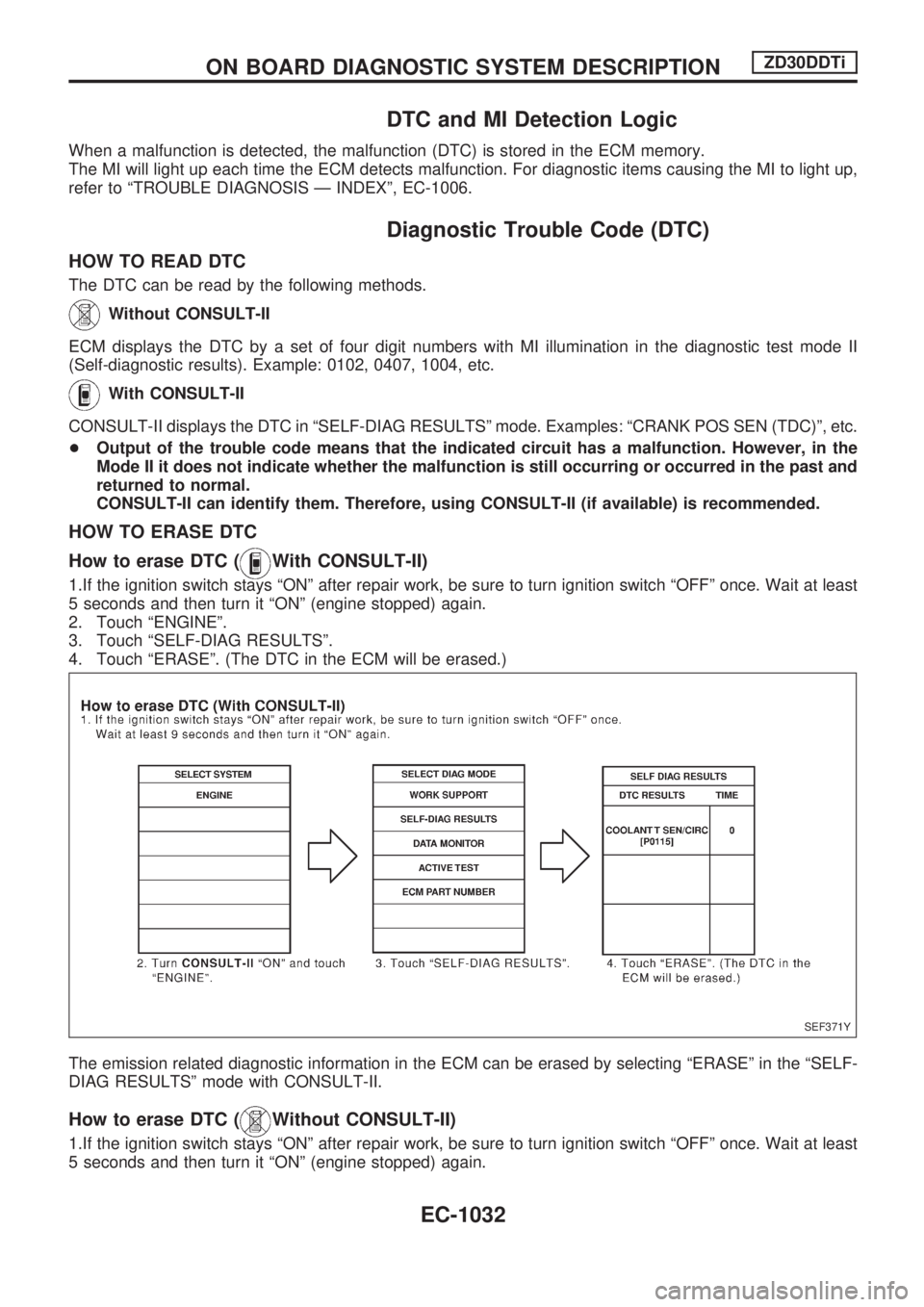
1.If the ignition switch stays ªONº after repair work, be sure to turn ignition switch ªOFFº once. Wait at least
5 seconds and then turn it ªONº (engine stopped) again.
2. Touch ªENGINEº.
3. Touch ªSELF-DIAG RESULTSº.
4. Touch ªERASEº. (The DTC in the ECM will be erased.)
The emission related diagnostic information in the ECM can be erased by selecting ªERASEº in the ªSELF-
DIAG RESULTSº mode with CONSULT-II.
How to erase DTC (Without CONSULT-II)
1.If the ignition switch stays ªONº after repair work, be sure to turn ignition switch ªOFFº once. Wait at least
5 seconds and then turn it ªONº (engine stopped) again.
SEF371Y
ON BOARD DIAGNOSTIC SYSTEM DESCRIPTIONZD30DDTi
EC-1032
Page 266 of 1033
2. Change the diagnostic test mode from Mode II to Mode I by using the data link connector. (See
EC-1035.)
The emission related diagnostic information in the ECM can be erased by changing the diagnostic test mode.
+If the battery is disconnected, the emission-related diagnostic information will be lost after
approx. 24 hours.
+Erasing the emission-related diagnostic information using CONSULT-II is easier and quicker than
switching the diagnostic test mode using the data link connector.
NATS (Nissan Anti-Theft System)
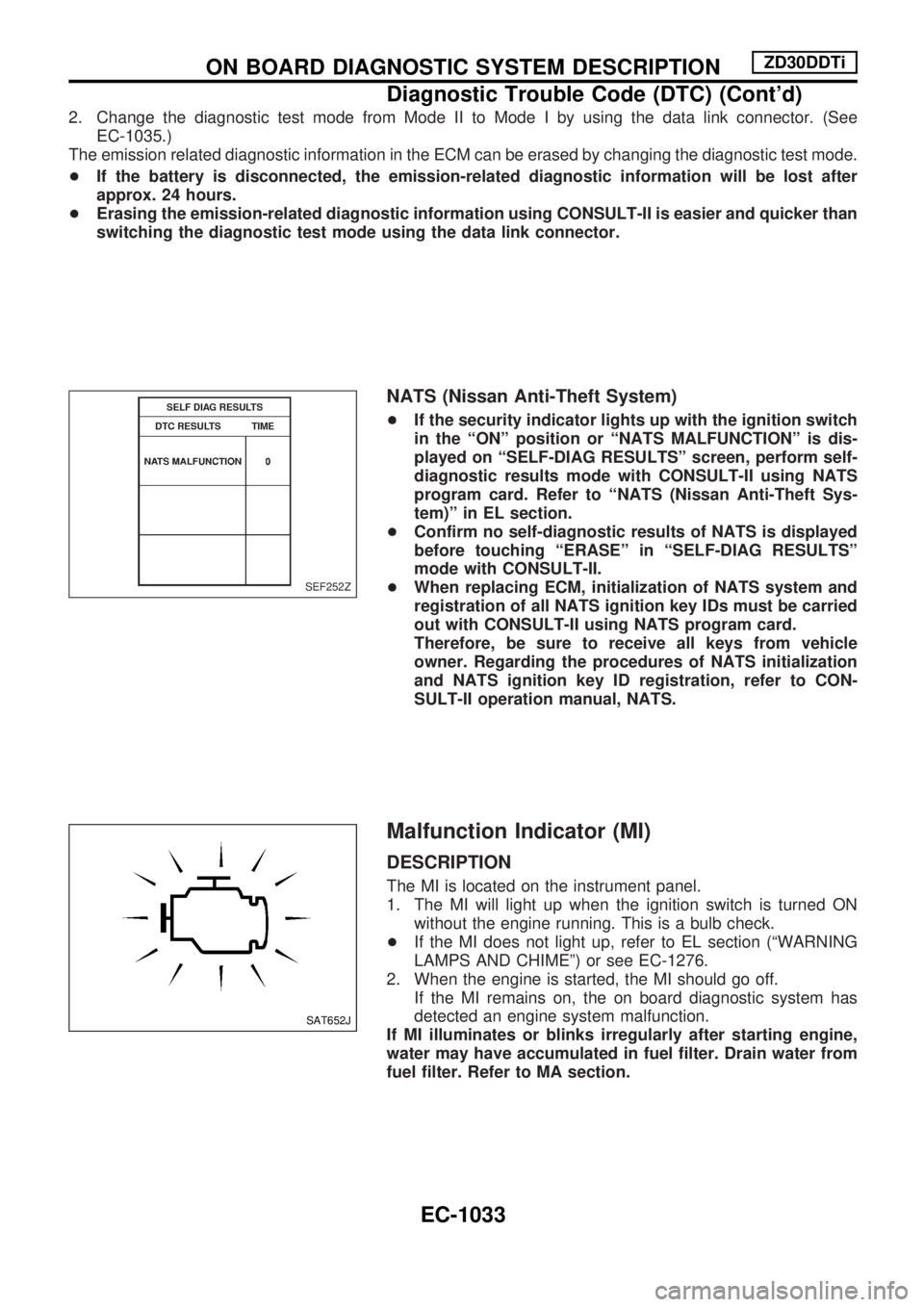
+If the security indicator lights up with the ignition switch
in the ªONº position or ªNATS MALFUNCTIONº is dis-
played on ªSELF-DIAG RESULTSº screen, perform self-
diagnostic results mode with CONSULT-II using NATS
program card. Refer to ªNATS (Nissan Anti-Theft Sys-
tem)º in EL section.
+Confirm no self-diagnostic results of NATS is displayed
before touching ªERASEº in ªSELF-DIAG RESULTSº
mode with CONSULT-II.
+When replacing ECM, initialization of NATS system and
registration of all NATS ignition key IDs must be carried
out with CONSULT-II using NATS program card.
Therefore, be sure to receive all keys from vehicle
owner. Regarding the procedures of NATS initialization
and NATS ignition key ID registration, refer to CON-
SULT-II operation manual, NATS.
Malfunction Indicator (MI)
DESCRIPTION
The MI is located on the instrument panel.
1. The MI will light up when the ignition switch is turned ON
without the engine running. This is a bulb check.
+If the MI does not light up, refer to EL section (ªWARNING
LAMPS AND CHIMEº) or see EC-1276.
2. When the engine is started, the MI should go off.
If the MI remains on, the on board diagnostic system has
detected an engine system malfunction.
If MI illuminates or blinks irregularly after starting engine,
water may have accumulated in fuel filter. Drain water from
fuel filter. Refer to MA section.
SEF252Z
SAT652J
ON BOARD DIAGNOSTIC SYSTEM DESCRIPTIONZD30DDTi
Diagnostic Trouble Code (DTC) (Cont'd)
EC-1033
Page 270 of 1033
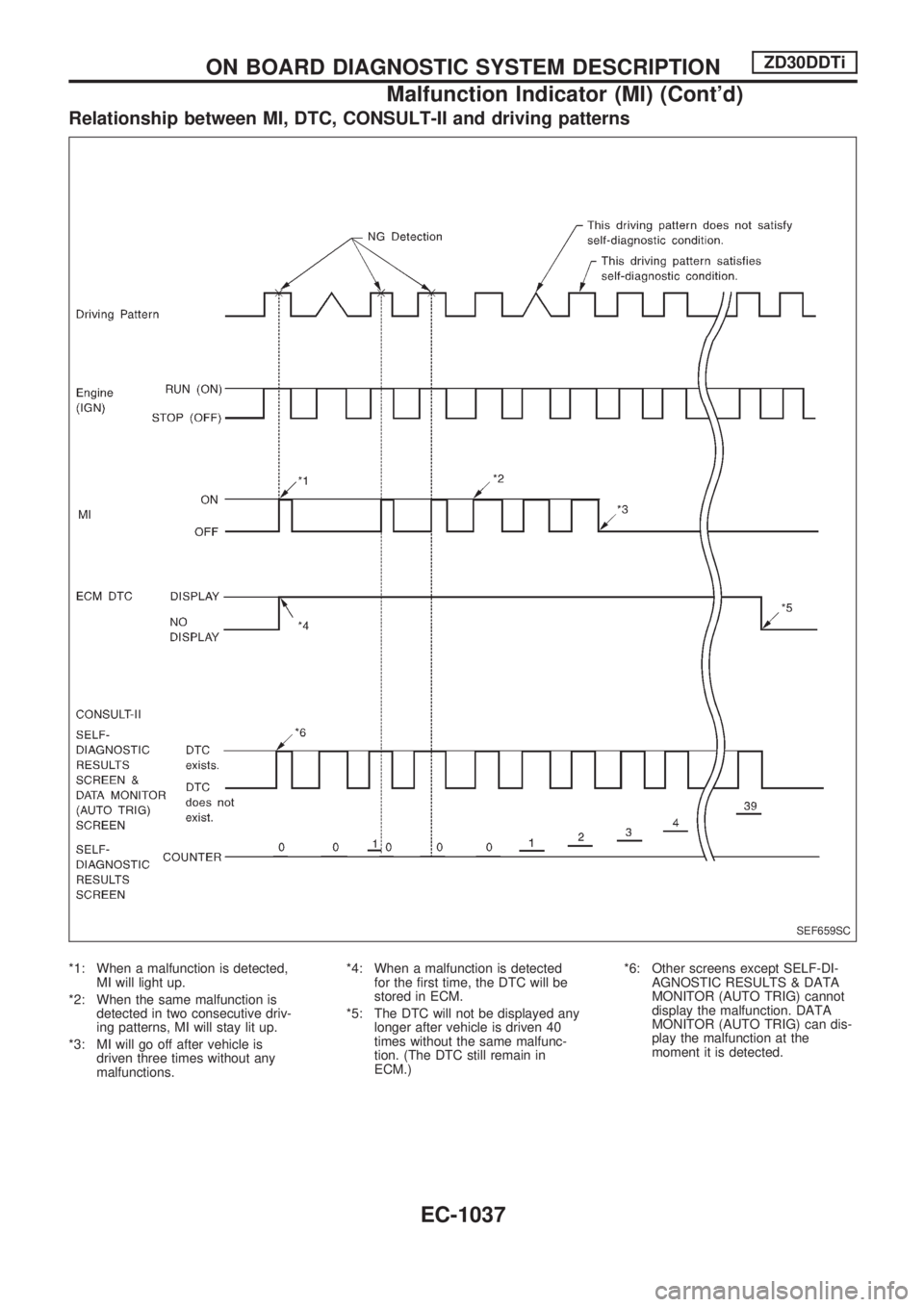
Relationship between MI, DTC, CONSULT-II and driving patterns
*1: When a malfunction is detected,
MI will light up.
*2: When the same malfunction is
detected in two consecutive driv-
ing patterns, MI will stay lit up.
*3: MI will go off after vehicle is
driven three times without any
malfunctions.*4: When a malfunction is detected
for the first time, the DTC will be
stored in ECM.
*5: The DTC will not be displayed any
longer after vehicle is driven 40
times without the same malfunc-
tion. (The DTC still remain in
ECM.)*6: Other screens except SELF-DI-
AGNOSTIC RESULTS & DATA
MONITOR (AUTO TRIG) cannot
display the malfunction. DATA
MONITOR (AUTO TRIG) can dis-
play the malfunction at the
moment it is detected.
SEF659SC
ON BOARD DIAGNOSTIC SYSTEM DESCRIPTIONZD30DDTi
Malfunction Indicator (MI) (Cont'd)
EC-1037
Page 272 of 1033
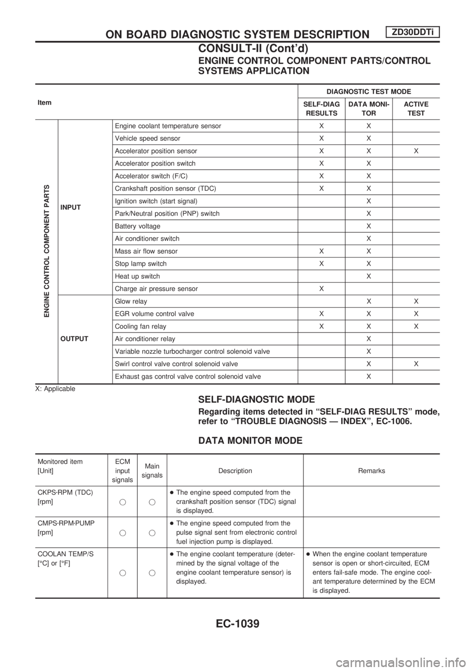
ENGINE CONTROL COMPONENT PARTS/CONTROL
SYSTEMS APPLICATION
ItemDIAGNOSTIC TEST MODE
SELF-DIAG
RESULTSDATA MONI-
TORACTIVE
TEST
ENGINE CONTROL COMPONENT PARTS
INPUTEngine coolant temperature sensor X X
Vehicle speed sensor X X
Accelerator position sensor X X X
Accelerator position switch X X
Accelerator switch (F/C) X X
Crankshaft position sensor (TDC) X X
Ignition switch (start signal) X
Park/Neutral position (PNP) switch X
Battery voltage X
Air conditioner switch X
Mass air flow sensor X X
Stop lamp switch X X
Heat up switch X
Charge air pressure sensor X
OUTPUTGlow relayXX
EGR volume control valve X X X
Cooling fan relay X X X
Air conditioner relay X
Variable nozzle turbocharger control solenoid valve X
Swirl control valve control solenoid valve X X
Exhaust gas control valve control solenoid valve X
X: Applicable
SELF-DIAGNOSTIC MODE
Regarding items detected in ªSELF-DIAG RESULTSº mode,
refer to ªTROUBLE DIAGNOSIS Ð INDEXº, EC-1006.
DATA MONITOR MODE
Monitored item
[Unit]ECM
input
signalsMain
signalsDescription Remarks
CKPSzRPM (TDC)
[rpm]jj+The engine speed computed from the
crankshaft position sensor (TDC) signal
is displayed.
CMPSzRPMzPUMP
[rpm]jj+The engine speed computed from the
pulse signal sent from electronic control
fuel injection pump is displayed.
COOLAN TEMP/S
[ÉC] or [ÉF]
jj+The engine coolant temperature (deter-
mined by the signal voltage of the
engine coolant temperature sensor) is
displayed.+When the engine coolant temperature
sensor is open or short-circuited, ECM
enters fail-safe mode. The engine cool-
ant temperature determined by the ECM
is displayed.
ON BOARD DIAGNOSTIC SYSTEM DESCRIPTIONZD30DDTi
CONSULT-II (Cont'd)
EC-1039
Page 273 of 1033
![NISSAN PATROL 2000 Electronic Repair Manual Monitored item
[Unit]ECM
input
signalsMain
signalsDescription Remarks
VHCL SPEED SE
[km/h] or [mph]jj+The vehicle speed computed from the
vehicle speed sensor signal is displayed.
FUEL TEMP SEN
[ÉC] NISSAN PATROL 2000 Electronic Repair Manual Monitored item
[Unit]ECM
input
signalsMain
signalsDescription Remarks
VHCL SPEED SE
[km/h] or [mph]jj+The vehicle speed computed from the
vehicle speed sensor signal is displayed.
FUEL TEMP SEN
[ÉC]](/manual-img/5/57367/w960_57367-272.png)
Monitored item
[Unit]ECM
input
signalsMain
signalsDescription Remarks
VHCL SPEED SE
[km/h] or [mph]jj+The vehicle speed computed from the
vehicle speed sensor signal is displayed.
FUEL TEMP SEN
[ÉC] or [ÉF]jj+The fuel temperature (sent from elec-
tronic control fuel injection pump) is dis-
played.
ACCEL POS SEN [V]
jj+The accelerator position sensor signal
voltage is displayed.
FULL ACCEL SW
[ON/OFF]jj+Indicates [ON/OFF] condition from the
accelerator position switch signal.
ACCEL SW (FC)
[OPEN/CLOSE]jj+Indicates [OPEN/CLOSE] condition from
the accelerator switch (FC) signal.
OFF ACCEL SW
[ON/OFF]jj+Indicates [ON/OFF] condition from the
accelerator position switch signal.
SPILL/V [ÉCA]
j+The control position of spill valve (sent
from electronic control fuel injection
pump) is displayed.
BATTERY VOLT [V]
jj+The power supply voltage of ECM is dis-
played.
P/N POSI SW
[ON/OFF]jj+Indicates [ON/OFF] condition from the
park/neutral position switch signal.
START SIGNAL
[ON/OFF]jj+Indicates [ON/OFF] condition from the
starter signal.+After starting the engine, [OFF] is dis-
played regardless of the starter signal.
AIR COND SIG
[ON/OFF]jj+Indicates [ON/OFF] condition of the air
conditioner switch as determined by the
air conditioner signal.
BRAKE SW [ON/OFF]
jj+Indicates [ON/OFF] condition from the
stop lamp switch signal.
IGN SW
[ON/OFF]jj+Indicates [ON/OFF] condition from igni-
tion switch signal.
WARM UP SW
[ON/OFF]j+Indicates [ON/OFF] condition from the
heat up switch signal.
MAS AIR/FL SE [V]
jj+The signal voltage of the mass air flow
sensor is displayed.+When the engine is stopped, a certain
value is indicated.
DECELER F/CUT
[ON/OFF]j+The [ON/OFF] condition from decelera-
tion fuel cut signal (sent from electronic
control fuel injection pump) is displayed.
INJ TIMG C/V [%]
j+The duty ratio of fuel injection timing
control valve (sent from electronic con-
trol fuel injection pump) is displayed.
AIR COND RLY
[ON/OFF]j+Indicates the control condition of the air
conditioner relay (determined by ECM
according to the input signals).
GLOW RLY [ON/OFF]
j+The glow relay control condition (deter-
mined by ECM according to the input
signal) is displayed.
ON BOARD DIAGNOSTIC SYSTEM DESCRIPTIONZD30DDTi
CONSULT-II (Cont'd)
EC-1040
Page 274 of 1033
![NISSAN PATROL 2000 Electronic Repair Manual Monitored item
[Unit]ECM
input
signalsMain
signalsDescription Remarks
COOLING FAN
[ON/OFF]
j+Indicates the control condition of the
cooling fans (determined by ECM
according to the input signal).
+ON NISSAN PATROL 2000 Electronic Repair Manual Monitored item
[Unit]ECM
input
signalsMain
signalsDescription Remarks
COOLING FAN
[ON/OFF]
j+Indicates the control condition of the
cooling fans (determined by ECM
according to the input signal).
+ON](/manual-img/5/57367/w960_57367-273.png)
Monitored item
[Unit]ECM
input
signalsMain
signalsDescription Remarks
COOLING FAN
[ON/OFF]
j+Indicates the control condition of the
cooling fans (determined by ECM
according to the input signal).
+ON ... Operates.
OFF ... Stopped.
EGR VOL CON/V
[step]
j+Indicates the EGR volume control value
computed by the ECM according to the
input signals.
+The opening becomes larger as the
value increases.
VNT S/V 1 [%]+Indicates the variable nozzle turbo-
charger control solenoid valve control
value computed by the ECM according
to the input signals.
BARO SEN [kPa]
j+The barometric pressure (determined by
the signal voltage from the barometric
pressure sensor built into the ECM) is
displayed.
SWRL CON S/V 1
[ON/OFF]
j+The control condition of the swirl control
valve control solenoid valve (determined
by ECM according to the input signals)
is indicated.
+ON ... Swirl control valve is closed.
+OFF ... Swirl control valve is opened.
EXH/GAS REG V
[ON/OFF]+The control condition of the exhaust gas
control valve control solenoid valve
(computed by ECM according to the
input signals) is indicated.
+ON ... Exhaust gas control valve is
closed.
+OFF ... Exhaust gas control valve is
opened.+This item is applicable for cold area
models.
On other models, ªOFFº is always dis-
played.
NOTE:
Any monitored item that does not match the vehicle being diagnosed is deleted from the display automatically.
ON BOARD DIAGNOSTIC SYSTEM DESCRIPTIONZD30DDTi
CONSULT-II (Cont'd)
EC-1041
Page 276 of 1033
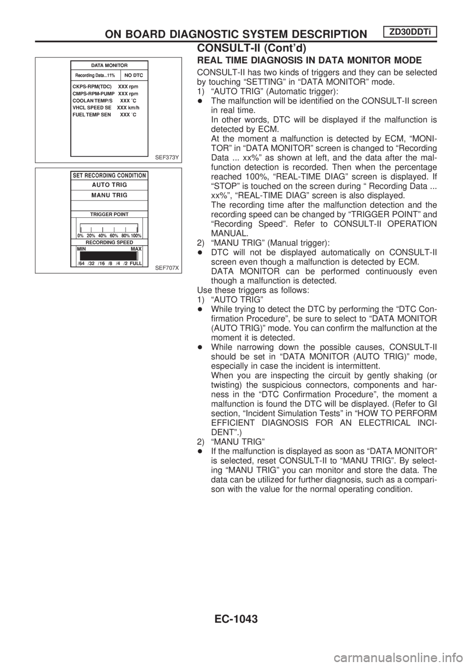
REAL TIME DIAGNOSIS IN DATA MONITOR MODE
CONSULT-II has two kinds of triggers and they can be selected
by touching ªSETTINGº in ªDATA MONITORº mode.
1) ªAUTO TRIGº (Automatic trigger):
+The malfunction will be identified on the CONSULT-II screen
in real time.
In other words, DTC will be displayed if the malfunction is
detected by ECM.
At the moment a malfunction is detected by ECM, ªMONI-
TORº in ªDATA MONITORº screen is changed to ªRecording
Data ... xx%º as shown at left, and the data after the mal-
function detection is recorded. Then when the percentage
reached 100%, ªREAL-TIME DIAGº screen is displayed. If
ªSTOPº is touched on the screen during ª Recording Data ...
xx%º, ªREAL-TIME DIAGº screen is also displayed.
The recording time after the malfunction detection and the
recording speed can be changed by ªTRIGGER POINTº and
ªRecording Speedº. Refer to CONSULT-II OPERATION
MANUAL.
2) ªMANU TRIGº (Manual trigger):
+DTC will not be displayed automatically on CONSULT-II
screen even though a malfunction is detected by ECM.
DATA MONITOR can be performed continuously even
though a malfunction is detected.
Use these triggers as follows:
1) ªAUTO TRIGº
+While trying to detect the DTC by performing the ªDTC Con-
firmation Procedureº, be sure to select to ªDATA MONITOR
(AUTO TRIG)º mode. You can confirm the malfunction at the
moment it is detected.
+While narrowing down the possible causes, CONSULT-II
should be set in ªDATA MONITOR (AUTO TRIG)º mode,
especially in case the incident is intermittent.
When you are inspecting the circuit by gently shaking (or
twisting) the suspicious connectors, components and har-
ness in the ªDTC Confirmation Procedureº, the moment a
malfunction is found the DTC will be displayed. (Refer to GI
section, ªIncident Simulation Testsº in ªHOW TO PERFORM
EFFICIENT DIAGNOSIS FOR AN ELECTRICAL INCI-
DENTº.)
2) ªMANU TRIGº
+If the malfunction is displayed as soon as ªDATA MONITORº
is selected, reset CONSULT-II to ªMANU TRIGº. By select-
ing ªMANU TRIGº you can monitor and store the data. The
data can be utilized for further diagnosis, such as a compari-
son with the value for the normal operating condition.
SEF373Y
SEF707X
ON BOARD DIAGNOSTIC SYSTEM DESCRIPTIONZD30DDTi
CONSULT-II (Cont'd)
EC-1043