Page 126 of 1033
Control Valve Assembly and Accumulators
REMOVAL
1. Drain ATF.
2. Remove oil pan and gasket.
3. Remove A/T fluid temperature sensor if necessary.
4. Remove oil strainer.
5. Remove control valve assembly by removing fixing bolts and
disconnecting harness connector.
Bolt length and location
Bolt symbol!mm (in)
VA33 (1.30)
VB45 (1.77)
6. Remove solenoids and valves from valve body if necessary.
7. Remove terminal cord assembly if necessary.
8. Remove accumulator
VA,VB,VCandVDby applying com-
pressed air if necessary.
+Hold each piston with rag.
9. Reinstall any part removed.
+Always use new sealing parts.
SAT260J
SAT073BA
SAT353B
SAT074BA
ON-VEHICLE SERVICE
AT-1124
Page 130 of 1033

14. Support A/T and transfer assembly with a jack.
15. Remove engine rear mounting member from body and A/T
assembly. Refer to EM section (ªENGINE REMOVALº).
16. Remove bolts securing A/T assembly to engine.
+Secure torque converter to prevent it from dropping.
+Secure A/T assembly with transfer to a jack.
17. Lower A/T assembly with transfer.
Installation
+Drive plate runout
CAUTION:
Do not allow any magnetic materials to contact the ring gear
teeth.
Maximum allowable runout:
Refer to EM section (ªInspectionº, CYLINDER
BLOCKº).
If this runout is out of specification, replace drive plate with
ring gear.
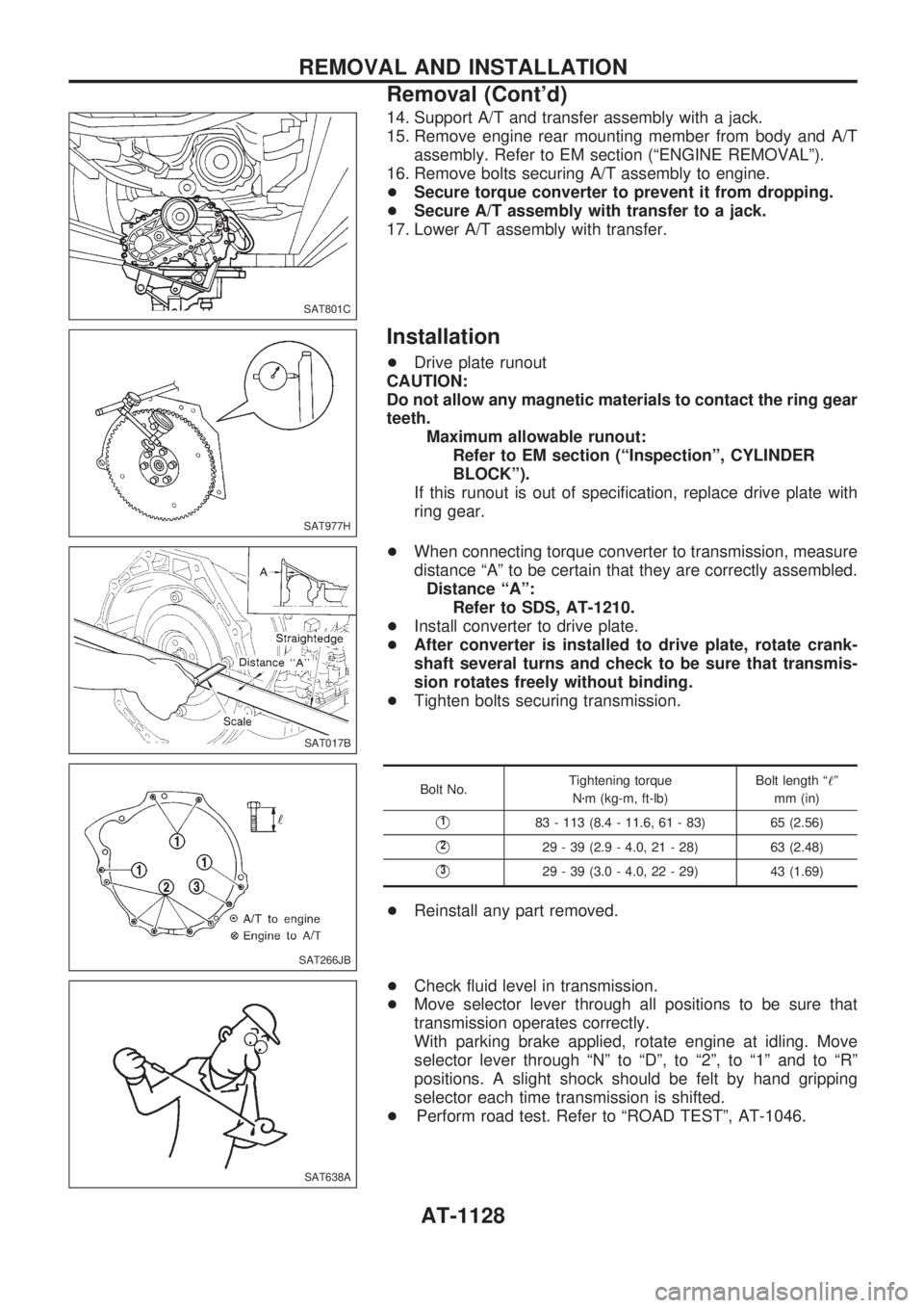
+When connecting torque converter to transmission, measure
distance ªAº to be certain that they are correctly assembled.
Distance ªAº:
Refer to SDS, AT-1210.
+Install converter to drive plate.
+After converter is installed to drive plate, rotate crank-
shaft several turns and check to be sure that transmis-
sion rotates freely without binding.
+Tighten bolts securing transmission.
Bolt No.Tightening torque
Nzm (kg-m, ft-lb)Bolt length ª!º
mm (in)
V183 - 113 (8.4 - 11.6, 61 - 83) 65 (2.56)
V229 - 39 (2.9 - 4.0, 21 - 28) 63 (2.48)
V329 - 39 (3.0 - 4.0, 22 - 29) 43 (1.69)
+Reinstall any part removed.
+Check fluid level in transmission.
+Move selector lever through all positions to be sure that
transmission operates correctly.
With parking brake applied, rotate engine at idling. Move
selector lever through ªNº to ªDº, to ª2º, to ª1º and to ªRº
positions. A slight shock should be felt by hand gripping
selector each time transmission is shifted.
+Perform road test. Refer to ªROAD TESTº, AT-1046.
SAT801C
SAT977H
SAT017B
SAT266JB
SAT638A
REMOVAL AND INSTALLATION
Removal (Cont'd)
AT-1128
Page 137 of 1033
10. Remove control valve assembly.
a. Straighten terminal clips to free terminal cords then remove
terminal clips.
b. Remove bolts
VAandVB, and remove control valve assem-
bly from transmission.
Bolt symbol Length mm (in)
VA33 (1.30)
VB45 (1.77)
c. Remove solenoid connector.
+Be careful not to damage connector.
d. Remove manual valve from control valve assembly.
SAT009B
SAT353B
SAT026B
SAT127B
DISASSEMBLY
AT-1135
Page 155 of 1033
g. Install and temporarily tighten bolts and tube brackets in their
proper locations.
Bolt length and location:
Bolt symbolVaVbVcVd
Bolt length mm (in)70
(2.76)50
(1.97)33
(1.30)27
(1.06)
2. Install solenoids.
a. Attach O-ring and install torque converter clutch solenoid
valve and side plates onto lower body.
b. Attach O-rings and install 3-unit solenoids assembly onto
upper body.
c. Attach O-ring and install line pressure solenoid valve onto
upper body.
3. Tighten all bolts.
SAT199BA
SAT200B
SAT150G
REPAIR FOR COMPONENT PARTS
Control Valve Assembly (Cont'd)
AT-1153
Page 158 of 1033

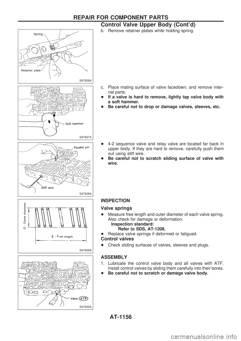
b. Remove retainer plates while holding spring.
c. Place mating surface of valve facedown, and remove inter-
nal parts.
+If a valve is hard to remove, lightly tap valve body with
a soft hammer.
+Be careful not to drop or damage valves, sleeves, etc.
+4-2 sequence valve and relay valve are located far back in
upper body. If they are hard to remove, carefully push them
out using stiff wire.
+Be careful not to scratch sliding surface of valve with
wire.
INSPECTION
Valve springs
+Measure free length and outer diameter of each valve spring.
Also check for damage or deformation.
Inspection standard:
Refer to SDS, AT-1208.
+Replace valve springs if deformed or fatigued.
Control valves
+Check sliding surfaces of valves, sleeves and plugs.
ASSEMBLY
1. Lubricate the control valve body and all valves with ATF.
Install control valves by sliding them carefully into their bores.
+Be careful not to scratch or damage valve body.
SAT826A
SAT827A
SAT828A
SAT829A
SAT830A
REPAIR FOR COMPONENT PARTS
Control Valve Upper Body (Cont'd)
AT-1156
Page 162 of 1033
DISASSEMBLY
1. Remove valves at parallel pins.
2. Remove valves at retainer plates.
For removal procedures, refer to ªDISASSEMBLYº of Control
Valve Upper Body, AT-1155.
INSPECTION
Valve springs
+Check each valve spring for damage or deformation. Also
measure free length and outer diameter.
Inspection standard:
Refer to SDS, AT-1208.
+Replace valve springs if deformed or fatigued.
Control valves
+Check sliding surfaces of control valves, sleeves and plugs
for damage.
ASSEMBLY
+Install control valves.
For installation procedures, refer to ªASSEMBLYº of Control
Valve Upper Body, AT-1156.
SAT838A
SAT829A
SAT838A
REPAIR FOR COMPONENT PARTS
Control Valve Lower Body (Cont'd)
AT-1160
Page 164 of 1033

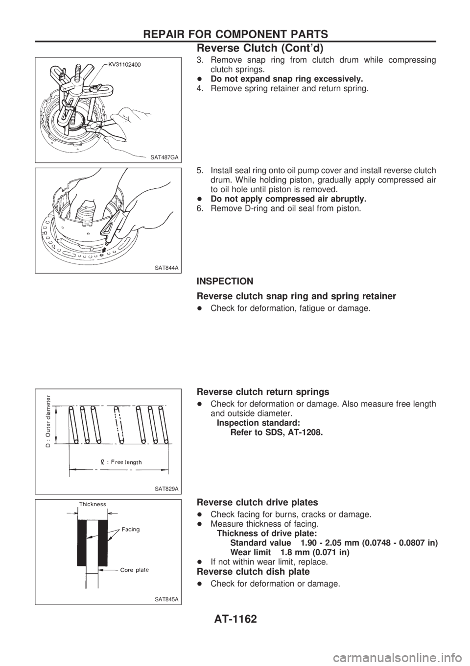
3. Remove snap ring from clutch drum while compressing
clutch springs.
+Do not expand snap ring excessively.
4. Remove spring retainer and return spring.
5. Install seal ring onto oil pump cover and install reverse clutch
drum. While holding piston, gradually apply compressed air
to oil hole until piston is removed.
+Do not apply compressed air abruptly.
6. Remove D-ring and oil seal from piston.
INSPECTION
Reverse clutch snap ring and spring retainer
+Check for deformation, fatigue or damage.
Reverse clutch return springs
+Check for deformation or damage. Also measure free length
and outside diameter.
Inspection standard:
Refer to SDS, AT-1208.
Reverse clutch drive plates
+Check facing for burns, cracks or damage.
+Measure thickness of facing.
Thickness of drive plate:
Standard value 1.90 - 2.05 mm (0.0748 - 0.0807 in)
Wear limit 1.8 mm (0.071 in)
+If not within wear limit, replace.
Reverse clutch dish plate
+Check for deformation or damage.
SAT487GA
SAT844A
SAT829A
SAT845A
REPAIR FOR COMPONENT PARTS
Reverse Clutch (Cont'd)
AT-1162
Page 174 of 1033
3. Remove low one-way clutch inner race, spring retainer and
return spring from transmission case.
4. Remove seal rings from low one-way clutch inner race.
5. Remove needle bearing from low one-way clutch inner race.
6. Remove low and reverse brake piston using compressed air.
7. Remove oil seal and D-ring from piston.
INSPECTION
Low and reverse brake snap ring and spring retainer
+Check for deformation, or damage.
Low and reverse brake return springs
+Check for deformation or damage. Also measure free length
and outside diameter.
Inspection standard:
Refer to SDS, AT-1208.
Low and reverse brake drive plates
+Check facing for burns, cracks or damage.
+Measure thickness of facing.
Thickness of drive plate:
Standard value
1.52 - 1.67 mm (0.0598 - 0.0657 in)
Wear limit
1.4 mm (0.055 in)
+If not within wear limit, replace.
SAT382I
SAT876A
SAT829A
SAT845A
REPAIR FOR COMPONENT PARTS
Low & Reverse Brake (Cont'd)
AT-1172