2000 NISSAN PATROL timing belt
[x] Cancel search: timing beltPage 234 of 1033
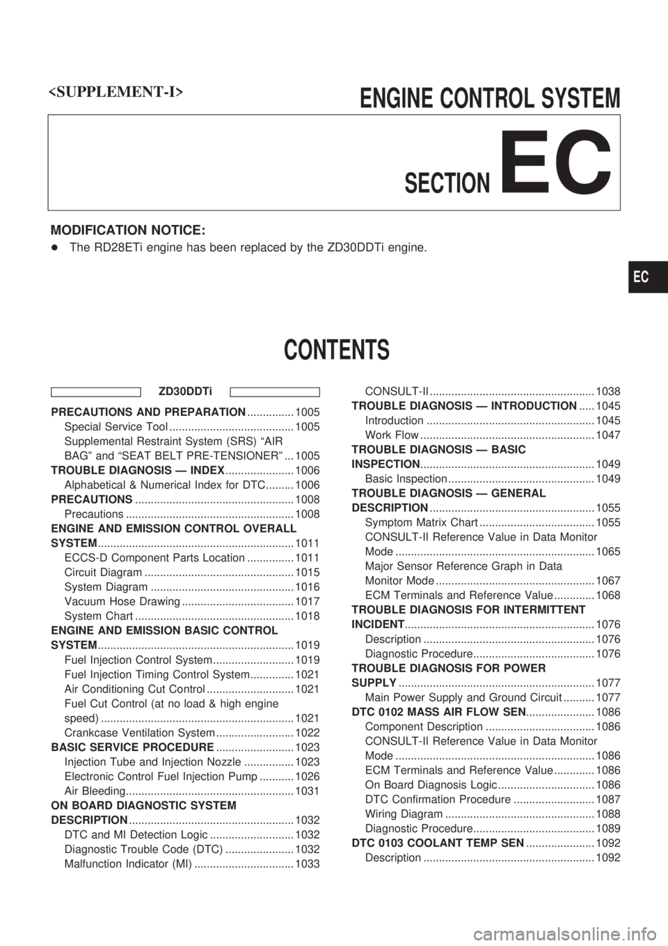
ENGINE CONTROL SYSTEM
SECTION
EC
MODIFICATION NOTICE:
+The RD28ETi engine has been replaced by the ZD30DDTi engine.
CONTENTS
ZD30DDTi
PRECAUTIONS AND PREPARATION............... 1005
Special Service Tool ........................................ 1005
Supplemental Restraint System (SRS) ªAIR
BAGº and ªSEAT BELT PRE-TENSIONERº ... 1005
TROUBLE DIAGNOSIS Ð INDEX...................... 1006
Alphabetical & Numerical Index for DTC......... 1006
PRECAUTIONS................................................... 1008
Precautions ...................................................... 1008
ENGINE AND EMISSION CONTROL OVERALL
SYSTEM............................................................... 1011
ECCS-D Component Parts Location ............... 1011
Circuit Diagram ................................................ 1015
System Diagram .............................................. 1016
Vacuum Hose Drawing .................................... 1017
System Chart ................................................... 1018
ENGINE AND EMISSION BASIC CONTROL
SYSTEM............................................................... 1019
Fuel Injection Control System.......................... 1019
Fuel Injection Timing Control System.............. 1021
Air Conditioning Cut Control ............................ 1021
Fuel Cut Control (at no load & high engine
speed) .............................................................. 1021
Crankcase Ventilation System ......................... 1022
BASIC SERVICE PROCEDURE......................... 1023
Injection Tube and Injection Nozzle ................ 1023
Electronic Control Fuel Injection Pump ........... 1026
Air Bleeding...................................................... 1031
ON BOARD DIAGNOSTIC SYSTEM
DESCRIPTION..................................................... 1032
DTC and MI Detection Logic ........................... 1032
Diagnostic Trouble Code (DTC) ...................... 1032
Malfunction Indicator (MI) ................................ 1033CONSULT-II ..................................................... 1038
TROUBLE DIAGNOSIS Ð INTRODUCTION..... 1045
Introduction ...................................................... 1045
Work Flow ........................................................ 1047
TROUBLE DIAGNOSIS Ð BASIC
INSPECTION........................................................ 1049
Basic Inspection ............................................... 1049
TROUBLE DIAGNOSIS Ð GENERAL
DESCRIPTION..................................................... 1055
Symptom Matrix Chart ..................................... 1055
CONSULT-II Reference Value in Data Monitor
Mode ................................................................ 1065
Major Sensor Reference Graph in Data
Monitor Mode ................................................... 1067
ECM Terminals and Reference Value ............. 1068
TROUBLE DIAGNOSIS FOR INTERMITTENT
INCIDENT............................................................. 1076
Description ....................................................... 1076
Diagnostic Procedure....................................... 1076
TROUBLE DIAGNOSIS FOR POWER
SUPPLY............................................................... 1077
Main Power Supply and Ground Circuit .......... 1077
DTC 0102 MASS AIR FLOW SEN...................... 1086
Component Description ................................... 1086
CONSULT-II Reference Value in Data Monitor
Mode ................................................................ 1086
ECM Terminals and Reference Value ............. 1086
On Board Diagnosis Logic ............................... 1086
DTC Confirmation Procedure .......................... 1087
Wiring Diagram ................................................ 1088
Diagnostic Procedure....................................... 1089
DTC 0103 COOLANT TEMP SEN...................... 1092
Description ....................................................... 1092
EC
Page 747 of 1033
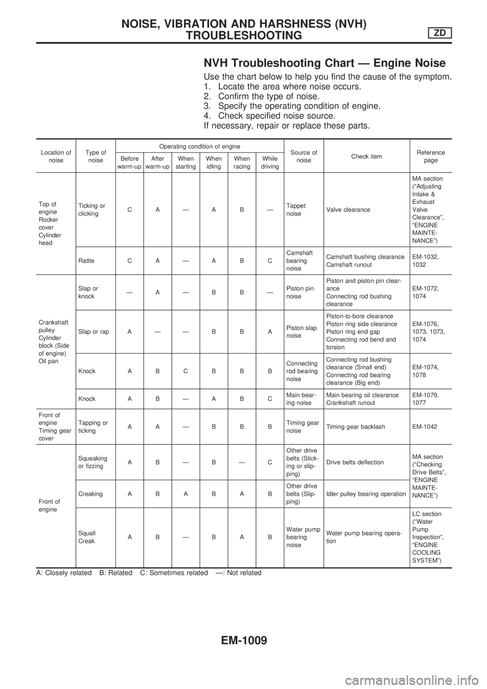
NVH Troubleshooting Chart Ð Engine Noise
Use the chart below to help you find the cause of the symptom.
1. Locate the area where noise occurs.
2. Confirm the type of noise.
3. Specify the operating condition of engine.
4. Check specified noise source.
If necessary, repair or replace these parts.
Location of
noiseType of
noiseOperating condition of engine
Source of
noiseCheck itemReference
page Before
warm-upAfter
warm-upWhen
startingWhen
idlingWhen
racingWhile
driving
Top of
engine
Rocker
cover
Cylinder
headTicking or
clickingCAÐABÐTappet
noiseValve clearanceMA section
(ªAdjusting
Intake &
Exhaust
Valve
Clearanceº,
ªENGINE
MAINTE-
NANCEº)
Rattle C A Ð A B CCamshaft
bearing
noiseCamshaft bushing clearance
Camshaft runoutEM-1032,
1032
Crankshaft
pulley
Cylinder
block (Side
of engine)
Oil panSlap or
knockÐAÐB BÐPiston pin
noisePiston and piston pin clear-
ance
Connecting rod bushing
clearanceEM-1072,
1074
Slap or rap A Ð Ð B B APiston slap
noisePiston-to-bore clearance
Piston ring side clearance
Piston ring end gap
Connecting rod bend and
torsionEM-1076,
1073, 1073,
1074
Knock A B C B B BConnecting
rod bearing
noiseConnecting rod bushing
clearance (Small end)
Connecting rod bearing
clearance (Big end)EM-1074,
1078
Knock A B Ð A B CMain bear-
ing noiseMain bearing oil clearance
Crankshaft runoutEM-1079,
1077
Front of
engine
Timing gear
coverTapping or
tickingAAÐBBBTiming gear
noiseTiming gear backlash EM-1042
Front of
engineSqueaking
or fizzingABÐBÐCOther drive
belts (Stick-
ing or slip-
ping)Drive belts deflectionMA section
(ªChecking
Drive Beltsº,
ªENGINE
MAINTE-
NANCEº) CreakingABABABOther drive
belts (Slip-
ping)Idler pulley bearing operation
Squall
CreakABÐBABWater pump
bearing
noiseWater pump bearing opera-
tionLC section
(ªWater
Pump
Inspectionº,
ªENGINE
COOLING
SYSTEMº)
A: Closely related B: Related C: Sometimes related Ð: Not related
NOISE, VIBRATION AND HARSHNESS (NVH)
TROUBLESHOOTINGZD
EM-1009
Page 765 of 1033
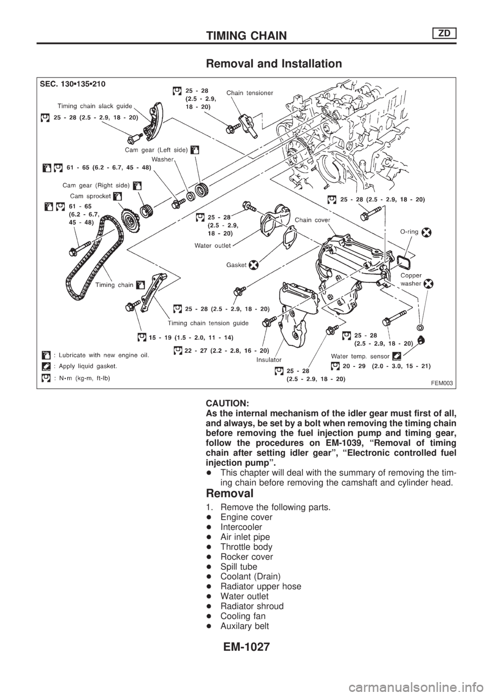
Removal and Installation
CAUTION:
As the internal mechanism of the idler gear must first of all,
and always, be set by a bolt when removing the timing chain
before removing the fuel injection pump and timing gear,
follow the procedures on EM-1039, ªRemoval of timing
chain after setting idler gearº, ªElectronic controlled fuel
injection pumpº.
+This chapter will deal with the summary of removing the tim-
ing chain before removing the camshaft and cylinder head.
Removal
1. Remove the following parts.
+Engine cover
+Intercooler
+Air inlet pipe
+Throttle body
+Rocker cover
+Spill tube
+Coolant (Drain)
+Radiator upper hose
+Water outlet
+Radiator shroud
+Cooling fan
+Auxilary belt
FEM003
TIMING CHAINZD
EM-1027
Page 778 of 1033
Removal
1. Remove the following parts.
+Undercover
+Engine oil (Drain)
+Engine coolant (Drain)
+Engine cover
+Intercooler
+Air inlet pipe
+Air cleaner case
+Throttle body
+Swirl and intake air control valve control solenoid valve and
bracket
+Vacuum tank
+Glow plate
+Rocker cover
+Spill tube
+Radiator shrouds (Rear and Lower)
+Cooling fan
+Radiator hose (Upper and Lower)
+Auxiliary belt and auto tensioner.
2. Remove the alternator.
3. Remove the A/C compressor and bracket with piping con-
nected. Move and support it at the LH side of engine bay with
a rope to avoid putting load on piping.
Refer to HA section in Nissan Service Manual (Supplement
I: Publication No. SM0E-Y61AE0E.)
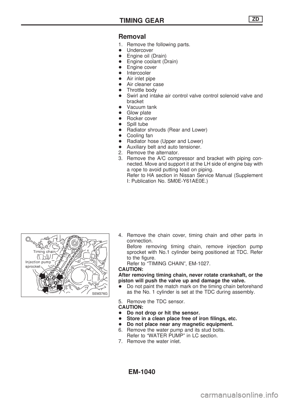
4. Remove the chain cover, timing chain and other parts in
connection.
Before removing timing chain, remove injection pump
sprocket with No.1 cylinder being positioned at TDC. Refer
to the figure.
Refer to ªTIMING CHAINº, EM-1027.
CAUTION:
After removing timing chain, never rotate crankshaft, or the
piston will push the valve up and damage the valve.
+Do not paint the match mark on the timing chain beforehand
as the No. 1 cylinder is set at the TDC during assembly.
5. Remove the TDC sensor.
CAUTION:
+Do not drop or hit the sensor.
+Store in a clean place free of iron filings, etc.
+Do not place near any magnetic equipment.
6. Remove the water pump and its stud bolts.
Refer to ªWATER PUMPº in LC section.
7. Remove the water inlet.
SEM376G
TIMING GEARZD
EM-1040
Page 807 of 1033
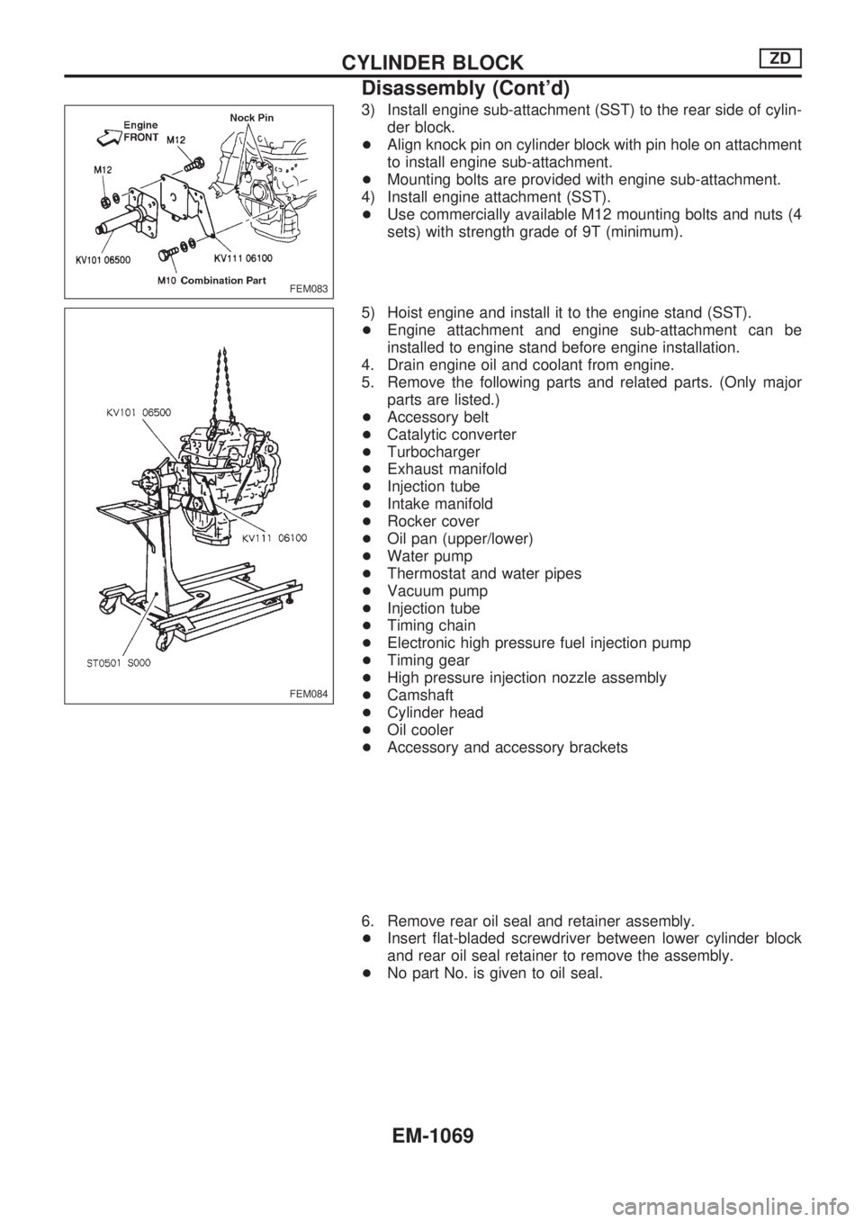
3) Install engine sub-attachment (SST) to the rear side of cylin-
der block.
+Align knock pin on cylinder block with pin hole on attachment
to install engine sub-attachment.
+Mounting bolts are provided with engine sub-attachment.
4) Install engine attachment (SST).
+Use commercially available M12 mounting bolts and nuts (4
sets) with strength grade of 9T (minimum).
5) Hoist engine and install it to the engine stand (SST).
+Engine attachment and engine sub-attachment can be
installed to engine stand before engine installation.
4. Drain engine oil and coolant from engine.
5. Remove the following parts and related parts. (Only major
parts are listed.)
+Accessory belt
+Catalytic converter
+Turbocharger
+Exhaust manifold
+Injection tube
+Intake manifold
+Rocker cover
+Oil pan (upper/lower)
+Water pump
+Thermostat and water pipes
+Vacuum pump
+Injection tube
+Timing chain
+Electronic high pressure fuel injection pump
+Timing gear
+High pressure injection nozzle assembly
+Camshaft
+Cylinder head
+Oil cooler
+Accessory and accessory brackets
6. Remove rear oil seal and retainer assembly.
+Insert flat-bladed screwdriver between lower cylinder block
and rear oil seal retainer to remove the assembly.
+No part No. is given to oil seal.
FEM083
FEM084
CYLINDER BLOCKZD
Disassembly (Cont'd)
EM-1069
Page 882 of 1033
O
Oil change (capacity) ............................ MA-1008
Oil pan (engine) .................................... EM-1022
Oil pump (A/T) ....................................... AT-1144
Oil seal replacement (engine) .............. EM-1051
On board diagnostic system ................. EC-1032
Operating cylinder (clutch) .................... CL-1003
Outside mirror ........................................ BT-1007
Overdrive control switch ........................ AT-1095
Overrun clutch solenoid valve ............... AT-1075
Overrun clutch ....................................... AT-1167
Oversize piston ..................................... EM-1075
P
P/ANT - Wiring diagram ........................ EL-1109
PCV (positive crankcase ventilation) .... EC-1022
PNP/SW - Wiring diagram .................... EC-1233
POWER - Wiring diagram ..................... EL-1005
Park/Neutral position switch ................. EC-1233
Park/neutral position switch (A/T) ......... AT-1095
Parking lamp .......................................... EL-1046
Pilot bushing replacement - See Pilot
converter ........................................... EM-1083
Piston pin inspection ............................ EM-1072
Piston ring inspection ........................... EM-1073
Piston to bore clearance ...................... EM-1076
Power antenna ...................................... EL-1109
Power supply routing ............................. EL-1004
Power window ....................................... EL-1115
Pressure test (A/T) ................................ AT-1044
Priming pump ........................................ EC-1049
Propeller shaft on vehicle service ......... PD-1003
Propeller shaft vibration ........................ PD-1003
Propeller shaft ....................................... PD-1002
Q
Quick-glow system ................................ EC-1221
R
R/COOL - Wiring diagram
(front auto A/C) ....................... HA-1013, 1017
R/COOL - Wiring diagram (front
manual A/C) ...................................... HA-1019
R/HEAT - Wiring diagram ..................... HA-1006
ROOM/L - Wiring diagram ..................... EL-1068
Radio - See Audio ................................. EL-1108
Rear cooler - Wiring diagram (front
auto A/C) ................................. HA-1013, 1017
Rear cooler - Wiring diagram (front
manual A/C) ...................................... HA-1019
Rear fog lamp ........................................ EL-1053
Rear heater - Wiring diagram ............... HA-1006Rear window defogger .......................... EL-1101
Refrigerant lines .................................... HA-1021
Removal and installation (A/T) .............. AT-1127
Reverse clutch ....................................... AT-1161
Revolution sensor (A/T) ........................ AT-1065
Room lamp - See Interior lamp ............. EL-1067
S
S/LOCK - Wiring diagram ...................... EL-1128
S/TANK - Wiring diagram ...................... FE-1003
SHIFT - Wiring diagram ........................ AT-1117
SRS - See Supplemental Restraint
System .............................................. RS-1003
STAB - Wiring diagram ......................... RA-1002
START - Wiring diagram ....................... EL-1036
SWL/V - Wiring diagram ....................... EC-1248
Screw jack .............................................. GI-1009
Seat belt pre-tensioner disposal ........... RS-1015
Seat belt pre-tensioner ......................... RS-1003
Seat, front .............................................. BT-1006
Self-diagnostic results ........................... EC-1034
Shift lock system ................................... AT-1116
Shift schedule ........................................ AT-1206
Shift solenoid valve A (A/T) .................. AT-1071
Shift solenoid valve B (A/T) .................. AT-1073
Side air bag ........................................... RS-1003
Speedometer ......................................... EL-1073
Spiral cable ........................................... RS-1009
Stabilizer release device - Wiring
diagram ............................................. RA-1002
Stabilizer release device ....................... RA-1002
Stall test (A/T) ....................................... AT-1041
Start signal ............................................ EC-1230
Starter .................................................... EL-1039
Starting system ...................................... EL-1036
Steering switch ...................................... EL-1043
Stop lamp .............................................. EL-1050
Super lock ................................... EL-1124, 1159
Supplemental Restraint System ........... RS-1003
Supplemental restraint system - Wiring
diagram ................................... RS-1024, 1028
Swirl control valve control solenoid
valve .................................................. EC-1246
Symptom matrix chart ........................... EC-1055
T
TCM circuit diagram .............................. AT-1008
TCM inspection table ............................ AT-1060
Tachometer ............................................ EL-1073
Tail lamp ................................................ EL-1046
Throttle position switch .......................... AT-1096
Timing chain ......................................... EM-1027
Timing gear ........................................... EM-1039
Torque converter clutch solenoid
valve .................................................. AT-1078
Torque converter installation ................. AT-1128
ALPHABETICAL INDEX
IDX-1004
Page 893 of 1033
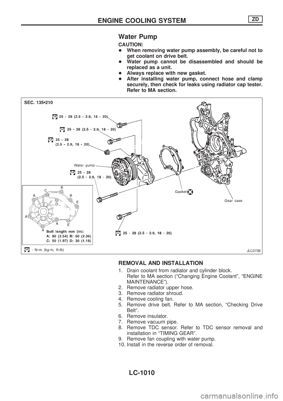
Water Pump
CAUTION:
+When removing water pump assembly, be careful not to
get coolant on drive belt.
+Water pump cannot be disassembled and should be
replaced as a unit.
+Always replace with new gasket.
+After installing water pump, connect hose and clamp
securely, then check for leaks using radiator cap tester.
Refer to MA section.
REMOVAL AND INSTALLATION
1. Drain coolant from radiator and cylinder block.
Refer to MA section (ªChanging Engine Coolantº, ªENGINE
MAINTENANCEº).
2. Remove radiator upper hose.
3. Remove radiator shroud.
4. Remove cooling fan.
5. Remove drive belt. Refer to MA section, ªChecking Drive
Beltº.
6. Remove insulator.
7. Remove vacuum pipe.
8. Remove TDC sensor. Refer to TDC sensor removal and
installation in ªTIMING GEARº.
9. Remove fan coupling with water pump.
10. Install in the reverse order of removal.
JLC373B
ENGINE COOLING SYSTEMZD
LC-1010