2000 NISSAN PATROL Defogger
[x] Cancel search: DefoggerPage 282 of 1033
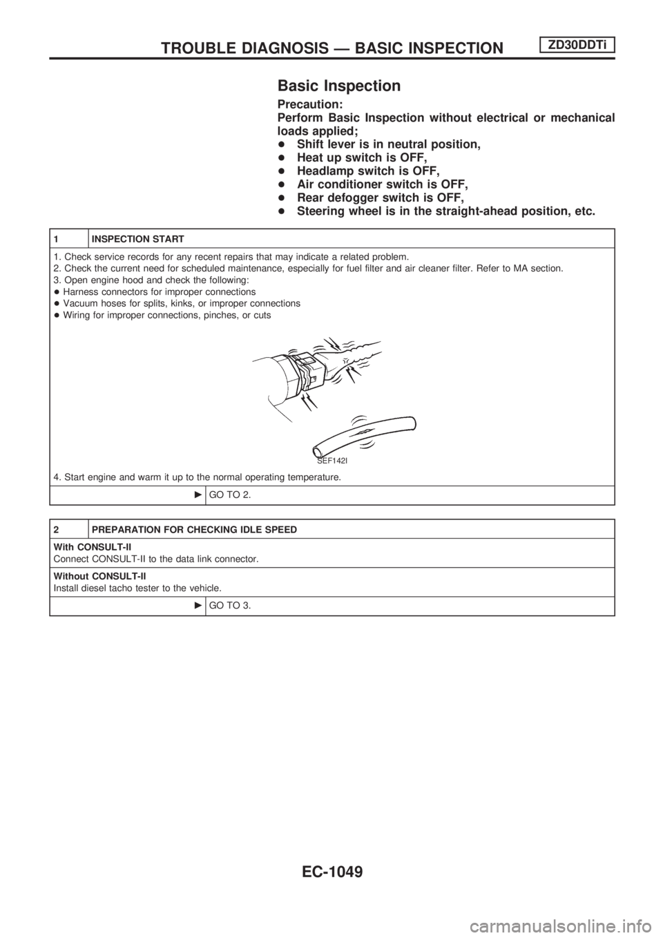
Basic Inspection
Precaution:
Perform Basic Inspection without electrical or mechanical
loads applied;
+Shift lever is in neutral position,
+Heat up switch is OFF,
+Headlamp switch is OFF,
+Air conditioner switch is OFF,
+Rear defogger switch is OFF,
+Steering wheel is in the straight-ahead position, etc.
1 INSPECTION START
1. Check service records for any recent repairs that may indicate a related problem.
2. Check the current need for scheduled maintenance, especially for fuel filter and air cleaner filter. Refer to MA section.
3. Open engine hood and check the following:
+Harness connectors for improper connections
+Vacuum hoses for splits, kinks, or improper connections
+Wiring for improper connections, pinches, or cuts
SEF142I
4. Start engine and warm it up to the normal operating temperature.
cGO TO 2.
2 PREPARATION FOR CHECKING IDLE SPEED
With CONSULT-II
Connect CONSULT-II to the data link connector.
Without CONSULT-II
Install diesel tacho tester to the vehicle.
cGO TO 3.
TROUBLE DIAGNOSIS Ð BASIC INSPECTIONZD30DDTi
EC-1049
Page 511 of 1033
ELECTRICAL SYSTEM
SECTION
EL
When you read wiring diagrams:
+Read GI section, ªHOW TO READ WIRING DIAGRAMSº.
When you perform trouble diagnoses, read GI section, ªHOW TO FOLLOW FLOW
CHART IN TROUBLE DIAGNOSESº and ªHOW TO PERFORM EFFICIENT DIAGNOSIS
FOR AN ELECTRICAL INCIDENTº.
+Check for any service bulletins before servicing the vehicle.
MODIFICATION NOTICE:
+Power window (driver's side only) with an interruption detection function has been adopted.
+ID code entry procedure of multi-remote control system has been changed.
+NATS (Nissan Anti-Theft System) has been adopted on ZD engine model.
CONTENTS
PRECAUTIONS AND PREPARATION............... 1003
Supplemental Restraint System (SRS) ªAIR
BAGº and ªSEAT BELT PRE-TENSIONERº ... 1003
POWER SUPPLY ROUTING............................... 1004
Schematic ........................................................ 1004
Wiring Diagram Ð POWER Ð ........................ 1005
GROUND DISTRIBUTION/LHD MODELS.......... 1013
Engine Room Harness..................................... 1013
Engine Control Harness................................... 1016
Main Harness ................................................... 1017
Body Harness .................................................. 1020
Body No. 2 Harness ........................................ 1022
Back Door and Rear Window Defogger
Harness ............................................................ 1023
GROUND DISTRIBUTION/RHD MODELS......... 1024
Engine Room Harness..................................... 1024
Engine Control Harness................................... 1027
Main Harness ................................................... 1028
Body Harness .................................................. 1031
Body No. 2 Harness ........................................ 1033
Back Door and Rear Window Defogger
Harness ............................................................ 1034
BATTERY............................................................. 1035
Service Data and Specifications (SDS) ........... 1035
STARTING SYSTEM........................................... 1036
Wiring Diagram Ð START Ð/M/T Models...... 1036
Wiring Diagram Ð START Ð/A/T Models ...... 1037
Construction ..................................................... 1038Service Data and Specifications (SDS) ........... 1039
CHARGING SYSTEM.......................................... 1040
Wiring Diagram Ð CHARGE ........................... 1040
Construction ..................................................... 1041
Service Data and Specifications (SDS) ........... 1041
COMBINATION SWITCH.................................... 1042
Check ............................................................... 1042
STEERING SWITCH............................................ 1043
Check ............................................................... 1043
HEADLAMP Ð Daytime Light System Ð........ 1044
Wiring Diagram Ð DTRL Ð ............................ 1044
PARKING, LICENSE AND TAIL LAMPS........... 1046
Wiring Diagram Ð TAIL/L Ð/LHD Models ...... 1046
Wiring Diagram Ð TAIL/L Ð/RHD Models ..... 1048
STOP LAMP........................................................ 1050
Wiring Diagram Ð STOP/L Ð......................... 1050
BACK-UP LAMP.................................................. 1051
Wiring Diagram Ð BACK/L Ð/RHD Models ... 1051
FRONT FOG LAMP............................................. 1052
Wiring Diagram Ð F/FOG Ð .......................... 1052
REAR FOG LAMP............................................... 1053
Wiring Diagram Ð R/FOG Ð .......................... 1053
CORNERING LAMP............................................ 1054
Wiring Diagram Ð CORNER Ð/LHD Models . 1054
System Description/RHD Models .................... 1055
Wiring Diagram Ð CORNER Ð/RHD Models1056
Trouble Diagnoses/RHD Models ..................... 1057
EL
Page 512 of 1033
TURN SIGNAL AND HAZARD WARNING
LAMPS................................................................. 1058
Wiring Diagram Ð TURN Ð ........................... 1058
ILLUMINATION .................................................... 1060
Schematic ........................................................ 1060
Wiring Diagram Ð ILL Ð ................................ 1061
INTERIOR ROOM LAMP ..................................... 1067
System Description .......................................... 1067
Wiring Diagram Ð ROOM/L Ð/LHD Models .. 1068
Wiring Diagram Ð ROOM/L Ð/RHD Models.. 1070
Trouble Diagnoses ........................................... 1072
METER AND GAUGES ....................................... 1073
Wiring Diagram Ð METER Ð/LHD Models .... 1073
Wiring Diagram Ð METER Ð/RHD Models ... 1075
WARNING LAMPS .............................................. 1078
Schematic ........................................................ 1078
Wiring Diagram Ð WARN Ð .......................... 1080
WARNING CHIME ............................................... 1091
System Description .......................................... 1091
Wiring Diagram Ð CHIME Ð/LHD Models ..... 1092
Wiring Diagram Ð CHIME Ð/RHD Models .... 1093
Trouble Diagnoses ........................................... 1094
Electrical Components Inspection ................... 1097
FRONT WIPER AND WASHER .......................... 1098
Wiring Diagram Ð WIPER Ð.......................... 1098
HEADLAMP WIPER AND WASHER .................. 1099
Wiring Diagram Ð HLC Ð .............................. 1099
HORN ................................................................... 1100
Wiring Diagram Ð HORN Ð ........................... 1100
REAR WINDOW DEFOGGER ............................. 1101
System Description .......................................... 1101
Wiring Diagram Ð DEF Ð/LHD Models ......... 1102
Wiring Diagram Ð DEF Ð/RHD Models......... 1104
Trouble Diagnoses ........................................... 1106
Electrical Components Inspection ................... 1107
AUDIO .................................................................. 1108
Wiring Diagram Ð REMOTE Ð ...................... 1108
AUDIO ANTENNA ............................................... 1109
Wiring Diagram Ð P/ANT Ð/RHD Models ..... 1109
AUTOMATIC SPEED CONTROL DEVICE
(ASCD) ................................................................. 1110
Schematic ........................................................ 1110
Wiring Diagram Ð ASCD Ð ........................... 1111
POWER WINDOW ............................................... 1115
System Description .......................................... 1115
Schematic ........................................................ 1116
Wiring Diagram Ð WINDOW Ð...................... 1117
Trouble Diagnoses ........................................... 1122
POWER DOOR LOCK Ð Super Lock Ð .......... 1124
Component Parts and Harness Connector
Location............................................................ 1124
System Description .......................................... 1125
Schematic ........................................................ 1127
Wiring Diagram Ð S/LOCK Ð/LHD Models ... 1128 Wiring Diagram Ð S/LOCK Ð/RHD Models... 1133
Trouble Diagnoses ........................................... 1138
MULTI-REMOTE CONTROL SYSTEM ............... 1149
System Description .......................................... 1149
Wiring Diagram Ð MULTI Ð/LHD Models...... 1150
Wiring Diagram Ð MULTI Ð/RHD Models ..... 1152
Trouble Diagnoses ........................................... 1154
ID Code Entry Procedure ................................ 1156
Remote Controller Battery Replacement ......... 1157
SUPER LOCK CONTROL UNIT ......................... 1159
Description ....................................................... 1159
Schematic ........................................................ 1160
Input/Output Operation Signal ......................... 1162
NATS (Nissan Anti-Theft System) .................... 1163
Component Parts and Harness Connector
Location............................................................ 1163
System Description .......................................... 1164
System Composition ........................................ 1165
Wiring Diagram Ð NATS Ð ............................ 1166
Wiring Diagram Ð NATS Ð/LHD Models ....... 1167
Wiring Diagram Ð NATS Ð/RHD Models ...... 1168
CONSULT-II ..................................................... 1169
Trouble Diagnoses ........................................... 1172
How to Replace NATS IMMU .......................... 1183
LOCATION OF ELECTRICAL UNITS ................. 1185
Engine Compartment ....................................... 1185
Passenger Compartment Ð LHD Models ....... 1186
Passenger Compartment Ð RHD Models ...... 1188
HARNESS LAYOUT ............................................ 1191
How to Read Harness Layout ......................... 1191
Main Harness/LHD Models .............................. 1192
Main Harness/RHD Models ............................. 1196
Engine Room Harness/LHD Models................ 1200
Engine Room Harness/RHD Models ............... 1204
Engine Harness ............................................... 1208
Engine Control Harness................................... 1209
Body Harness/LHD Models ............................. 1210
Body Harness/RHD Models ............................. 1214
Body No. 2 Harness/LHD Models ................... 1218
Body No. 2 Harness/RHD Models ................... 1220
Chassis Harness .............................................. 1222
Room Lamp Harness ....................................... 1223
Front Door Harness (Driver side) .................... 1224
Front Door Harness (Passenger side)............. 1225
Back Door Harness and Rear Window
Defogger Harness ............................................ 1226
WIRING DIAGRAM CODES (CELL CODES) ..... 1227
Wiring Diagram Codes (Cell Codes) ............... 1227
ELECTRICAL SYSTEM
Page 533 of 1033
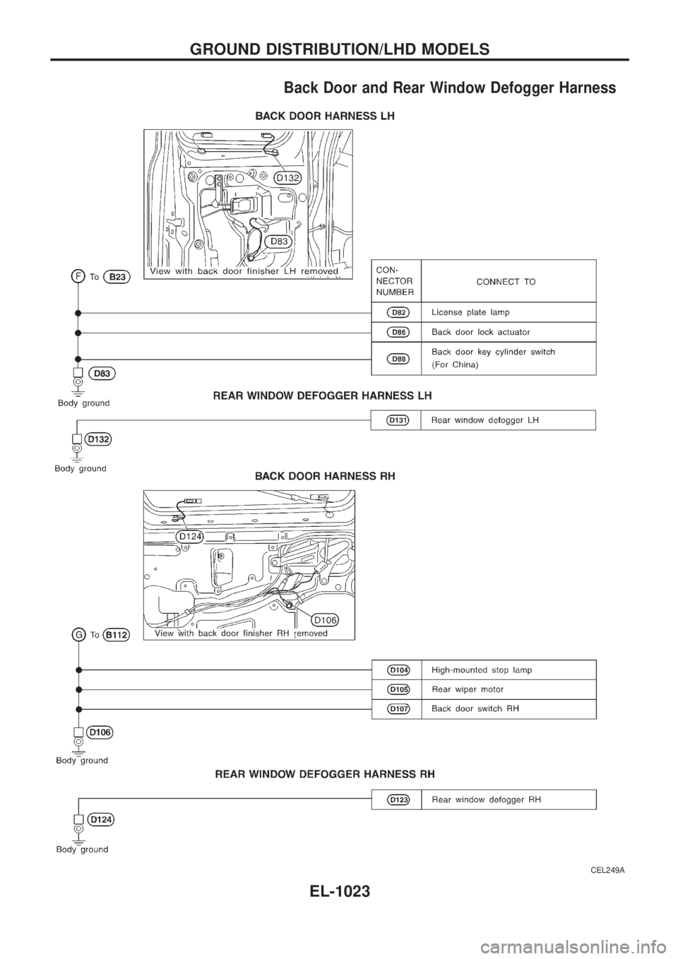
Back Door and Rear Window Defogger Harness
CEL249A
GROUND DISTRIBUTION/LHD MODELS
EL-1023
Page 544 of 1033
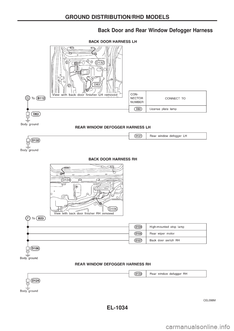
Back Door and Rear Window Defogger Harness
CEL098M
GROUND DISTRIBUTION/RHD MODELS
EL-1034
Page 611 of 1033
System Description
The rear window defogger system is controlled by the super lock control unit. The rear window defogger
operates only for approximately 15 minutes.
Power is supplied at all times
+to rear window defogger relay terminal
V3
+through 15A fuse (No.43, located in the fuse and fusible link box),
+to rear window defogger relay terminal
V6
+through 20A fuse (No.44, located in the fuse and fusible link box) and
+to super lock control unit terminal
V1
+through 7.5A fuse [No.24, located in the fuse block (J/B)].
With the ignition switch in the ON or START position, power is supplied
+to the rear window defogger relay terminal
V1
+through 7.5A fuse [No.8, located in the fuse block (J/B)] and
+to super lock control unit terminal
V17
+through 10A fuse [No.25, located in the fuse block (J/B)].
Ground is supplied to terminal
V2of the rear window defogger switch through body grounds.
When the rear window defogger switch is turned ON, ground is supplied
+through terminal
V1of the rear window defogger switch
+to super lock control unit terminal
V35.
Terminal
V27of the super lock control unit then supplies ground to the rear window defogger relay terminal
V2.
With power and ground supplied, the rear window defogger relay is energized.
Power is supplied
+through terminals
V5andV7of the rear window defogger relay
+to the rear window defogger and door mirror defogger (with door mirror defogger).
The rear window defogger has an independent ground.
With power and ground supplied, the rear window defogger filaments heat and defog the rear window.
When the system is activated, the rear window defogger indicator illuminates in the rear window defogger
switch.
Power is supplied
+to terminal
V3of the rear window defogger switch
+from terminal
V5of the rear window defogger relay.
Terminal
V4of the rear window defogger switch is grounded through body grounds.
REAR WINDOW DEFOGGER
EL-1101
Page 612 of 1033
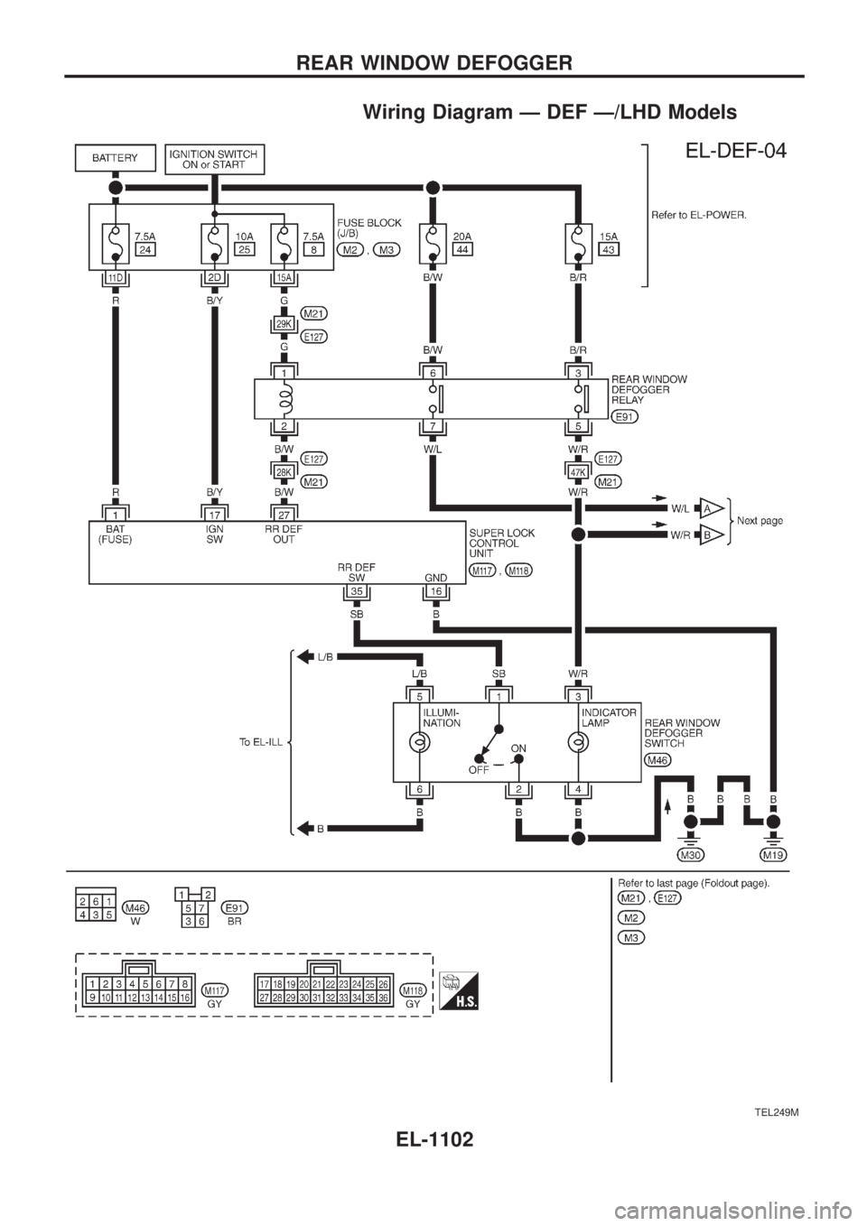
Wiring Diagram Ð DEF Ð/LHD Models
TEL249M
REAR WINDOW DEFOGGER
EL-1102
Page 613 of 1033
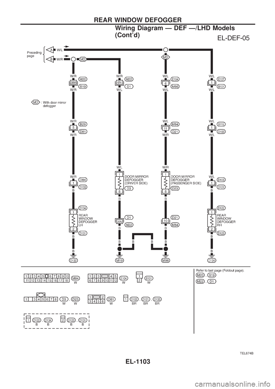
TEL674B
REAR WINDOW DEFOGGER
Wiring Diagram Ð DEF Ð/LHD Models
(Cont'd)
EL-1103