2000 NISSAN PATROL fuel pump
[x] Cancel search: fuel pumpPage 234 of 1033
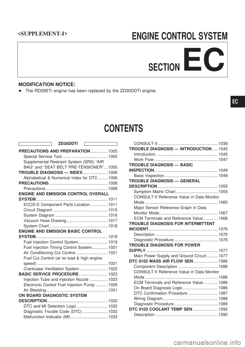
ENGINE CONTROL SYSTEM
SECTION
EC
MODIFICATION NOTICE:
+The RD28ETi engine has been replaced by the ZD30DDTi engine.
CONTENTS
ZD30DDTi
PRECAUTIONS AND PREPARATION............... 1005
Special Service Tool ........................................ 1005
Supplemental Restraint System (SRS) ªAIR
BAGº and ªSEAT BELT PRE-TENSIONERº ... 1005
TROUBLE DIAGNOSIS Ð INDEX...................... 1006
Alphabetical & Numerical Index for DTC......... 1006
PRECAUTIONS................................................... 1008
Precautions ...................................................... 1008
ENGINE AND EMISSION CONTROL OVERALL
SYSTEM............................................................... 1011
ECCS-D Component Parts Location ............... 1011
Circuit Diagram ................................................ 1015
System Diagram .............................................. 1016
Vacuum Hose Drawing .................................... 1017
System Chart ................................................... 1018
ENGINE AND EMISSION BASIC CONTROL
SYSTEM............................................................... 1019
Fuel Injection Control System.......................... 1019
Fuel Injection Timing Control System.............. 1021
Air Conditioning Cut Control ............................ 1021
Fuel Cut Control (at no load & high engine
speed) .............................................................. 1021
Crankcase Ventilation System ......................... 1022
BASIC SERVICE PROCEDURE......................... 1023
Injection Tube and Injection Nozzle ................ 1023
Electronic Control Fuel Injection Pump ........... 1026
Air Bleeding...................................................... 1031
ON BOARD DIAGNOSTIC SYSTEM
DESCRIPTION..................................................... 1032
DTC and MI Detection Logic ........................... 1032
Diagnostic Trouble Code (DTC) ...................... 1032
Malfunction Indicator (MI) ................................ 1033CONSULT-II ..................................................... 1038
TROUBLE DIAGNOSIS Ð INTRODUCTION..... 1045
Introduction ...................................................... 1045
Work Flow ........................................................ 1047
TROUBLE DIAGNOSIS Ð BASIC
INSPECTION........................................................ 1049
Basic Inspection ............................................... 1049
TROUBLE DIAGNOSIS Ð GENERAL
DESCRIPTION..................................................... 1055
Symptom Matrix Chart ..................................... 1055
CONSULT-II Reference Value in Data Monitor
Mode ................................................................ 1065
Major Sensor Reference Graph in Data
Monitor Mode ................................................... 1067
ECM Terminals and Reference Value ............. 1068
TROUBLE DIAGNOSIS FOR INTERMITTENT
INCIDENT............................................................. 1076
Description ....................................................... 1076
Diagnostic Procedure....................................... 1076
TROUBLE DIAGNOSIS FOR POWER
SUPPLY............................................................... 1077
Main Power Supply and Ground Circuit .......... 1077
DTC 0102 MASS AIR FLOW SEN...................... 1086
Component Description ................................... 1086
CONSULT-II Reference Value in Data Monitor
Mode ................................................................ 1086
ECM Terminals and Reference Value ............. 1086
On Board Diagnosis Logic ............................... 1086
DTC Confirmation Procedure .......................... 1087
Wiring Diagram ................................................ 1088
Diagnostic Procedure....................................... 1089
DTC 0103 COOLANT TEMP SEN...................... 1092
Description ....................................................... 1092
EC
Page 235 of 1033
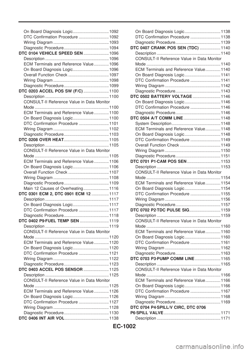
On Board Diagnosis Logic ............................... 1092
DTC Confirmation Procedure .......................... 1092
Wiring Diagram ................................................ 1093
Diagnostic Procedure....................................... 1094
DTC 0104 VEHICLE SPEED SEN...................... 1096
Description ....................................................... 1096
ECM Terminals and Reference Value ............. 1096
On Board Diagnosis Logic ............................... 1096
Overall Function Check ................................... 1097
Wiring Diagram ................................................ 1098
Diagnostic Procedure....................................... 1099
DTC 0203 ACCEL POS SW (F/C)...................... 1100
Description ....................................................... 1100
CONSULT-II Reference Value in Data Monitor
Mode ................................................................ 1100
ECM Terminals and Reference Value ............. 1100
On Board Diagnosis Logic ............................... 1100
DTC Confirmation Procedure .......................... 1101
Wiring Diagram ................................................ 1102
Diagnostic Procedure....................................... 1103
DTC 0208 OVER HEAT....................................... 1105
Description ....................................................... 1105
CONSULT-II Reference Value in Data Monitor
Mode ................................................................ 1105
ECM Terminals and Reference Value ............. 1106
On Board Diagnosis Logic ............................... 1106
Overall Function Check ................................... 1107
Wiring Diagram ................................................ 1108
Diagnostic Procedure....................................... 1109
Main 12 Causes of Overheating ...................... 1116
DTC 0301 ECM 2, DTC 0901 ECM 12............... 1117
Description ....................................................... 1117
On Board Diagnosis Logic ............................... 1117
DTC Confirmation Procedure .......................... 1117
Diagnostic Procedure....................................... 1118
DTC 0402 P9zFUEL TEMP SEN......................... 1119
Description ....................................................... 1119
CONSULT-II Reference Value in Data Monitor
Mode ................................................................ 1120
ECM Terminals and Reference Value ............. 1120
On Board Diagnosis Logic ............................... 1120
DTC Confirmation Procedure .......................... 1121
Wiring Diagram ................................................ 1122
Diagnostic Procedure....................................... 1123
DTC 0403 ACCEL POS SENSOR...................... 1125
Description ....................................................... 1125
CONSULT-II Reference Value in Data Monitor
Mode ................................................................ 1125
ECM Terminals and Reference Value ............. 1126
On Board Diagnosis Logic ............................... 1126
DTC Confirmation Procedure .......................... 1127
Wiring Diagram ................................................ 1128
Diagnostic Procedure....................................... 1130
DTC 0406 INT AIR VOL...................................... 1138On Board Diagnosis Logic ............................... 1138
DTC Confirmation Procedure .......................... 1138
Diagnostic Procedure....................................... 1139
DTC 0407 CRANK POS SEN (TDC).................. 1140
Description ....................................................... 1140
CONSULT-II Reference Value in Data Monitor
Mode ................................................................ 1140
ECM Terminals and Reference Value ............. 1140
On Board Diagnosis Logic ............................... 1141
DTC Confirmation Procedure .......................... 1141
Wiring Diagram ................................................ 1142
Diagnostic Procedure....................................... 1143
DTC 0502 BATTERY VOLTAGE........................ 1146
On Board Diagnosis Logic ............................... 1146
DTC Confirmation Procedure .......................... 1146
Diagnostic Procedure....................................... 1146
DTC 0504 A/T COMM LINE................................ 1148
System Description .......................................... 1148
ECM Terminals and Reference Value ............. 1148
On Board Diagnosis Logic ............................... 1148
DTC Confirmation Procedure .......................... 1149
Overall Function Check ................................... 1149
Wiring Diagram ................................................ 1150
Diagnostic Procedure....................................... 1151
DTC 0701 P1zCAM POS SEN............................. 1153
Description ....................................................... 1153
CONSULT-II Reference Value in Data Monitor
Mode ................................................................ 1154
ECM Terminals and Reference Value ............. 1154
On Board Diagnosis Logic ............................... 1154
DTC Confirmation Procedure .......................... 1155
Wiring Diagram ................................................ 1156
Diagnostic Procedure....................................... 1157
DTC 0702 P2zTDC PULSE SIG........................... 1159
Description ....................................................... 1159
CONSULT-II Reference Value in Data Monitor
Mode ................................................................ 1160
ECM Terminals and Reference Value ............. 1160
On Board Diagnosis Logic ............................... 1160
DTC Confirmation Procedure .......................... 1161
Wiring Diagram ................................................ 1162
Diagnostic Procedure....................................... 1163
DTC 0703 P3zPUMP COMM LINE...................... 1165
Description ....................................................... 1165
CONSULT-II Reference Value in Data Monitor
Mode ................................................................ 1166
ECM Terminals and Reference Value ............. 1166
On Board Diagnosis Logic ............................... 1166
DTC Confirmation Procedure .......................... 1167
Wiring Diagram ................................................ 1168
Diagnostic Procedure....................................... 1169
DTC 0704 P4zSPILL/V CIRC, DTC 0706
P6zSPILL VALVE................................................. 1171
Description ....................................................... 1171
EC-1002
Page 236 of 1033
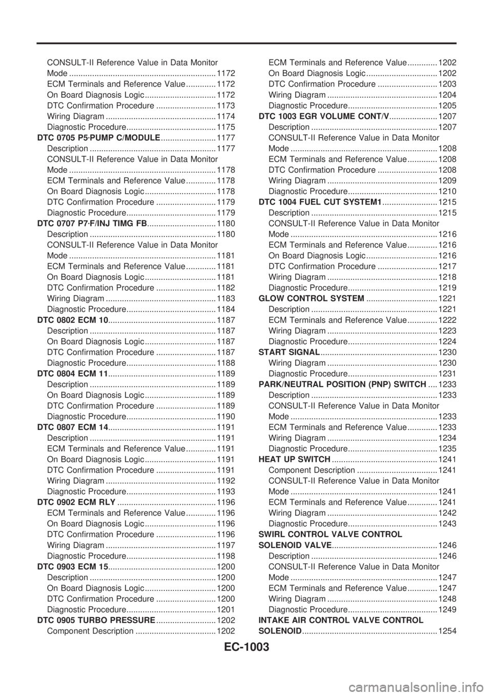
CONSULT-II Reference Value in Data Monitor
Mode ................................................................ 1172
ECM Terminals and Reference Value ............. 1172
On Board Diagnosis Logic ............................... 1172
DTC Confirmation Procedure .......................... 1173
Wiring Diagram ................................................ 1174
Diagnostic Procedure....................................... 1175
DTC 0705 P5zPUMP C/MODULE........................ 1177
Description ....................................................... 1177
CONSULT-II Reference Value in Data Monitor
Mode ................................................................ 1178
ECM Terminals and Reference Value ............. 1178
On Board Diagnosis Logic ............................... 1178
DTC Confirmation Procedure .......................... 1179
Diagnostic Procedure....................................... 1179
DTC 0707 P7zF/INJ TIMG FB.............................. 1180
Description ....................................................... 1180
CONSULT-II Reference Value in Data Monitor
Mode ................................................................ 1181
ECM Terminals and Reference Value ............. 1181
On Board Diagnosis Logic ............................... 1181
DTC Confirmation Procedure .......................... 1182
Wiring Diagram ................................................ 1183
Diagnostic Procedure....................................... 1184
DTC 0802 ECM 10............................................... 1187
Description ....................................................... 1187
On Board Diagnosis Logic ............................... 1187
DTC Confirmation Procedure .......................... 1187
Diagnostic Procedure....................................... 1188
DTC 0804 ECM 11............................................... 1189
Description ....................................................... 1189
On Board Diagnosis Logic ............................... 1189
DTC Confirmation Procedure .......................... 1189
Diagnostic Procedure....................................... 1190
DTC 0807 ECM 14............................................... 1191
Description ....................................................... 1191
ECM Terminals and Reference Value ............. 1191
On Board Diagnosis Logic ............................... 1191
DTC Confirmation Procedure .......................... 1191
Wiring Diagram ................................................ 1192
Diagnostic Procedure....................................... 1193
DTC 0902 ECM RLY........................................... 1196
ECM Terminals and Reference Value ............. 1196
On Board Diagnosis Logic ............................... 1196
DTC Confirmation Procedure .......................... 1196
Wiring Diagram ................................................ 1197
Diagnostic Procedure....................................... 1198
DTC 0903 ECM 15............................................... 1200
Description ....................................................... 1200
On Board Diagnosis Logic ............................... 1200
DTC Confirmation Procedure .......................... 1200
Diagnostic Procedure....................................... 1201
DTC 0905 TURBO PRESSURE.......................... 1202
Component Description ................................... 1202ECM Terminals and Reference Value ............. 1202
On Board Diagnosis Logic ............................... 1202
DTC Confirmation Procedure .......................... 1203
Wiring Diagram ................................................ 1204
Diagnostic Procedure....................................... 1205
DTC 1003 EGR VOLUME CONT/V..................... 1207
Description ....................................................... 1207
CONSULT-II Reference Value in Data Monitor
Mode ................................................................ 1208
ECM Terminals and Reference Value ............. 1208
DTC Confirmation Procedure .......................... 1208
Wiring Diagram ................................................ 1209
Diagnostic Procedure....................................... 1210
DTC 1004 FUEL CUT SYSTEM1........................ 1215
Description ....................................................... 1215
CONSULT-II Reference Value in Data Monitor
Mode ................................................................ 1216
ECM Terminals and Reference Value ............. 1216
On Board Diagnosis Logic ............................... 1216
DTC Confirmation Procedure .......................... 1217
Wiring Diagram ................................................ 1218
Diagnostic Procedure....................................... 1219
GLOW CONTROL SYSTEM............................... 1221
Description ....................................................... 1221
ECM Terminals and Reference Value ............. 1222
Wiring Diagram ................................................ 1223
Diagnostic Procedure....................................... 1224
START SIGNAL................................................... 1230
Wiring Diagram ................................................ 1230
Diagnostic Procedure....................................... 1231
PARK/NEUTRAL POSITION (PNP) SWITCH.... 1233
Description ....................................................... 1233
CONSULT-II Reference Value in Data Monitor
Mode ................................................................ 1233
ECM Terminals and Reference Value ............. 1233
Wiring Diagram ................................................ 1234
Diagnostic Procedure....................................... 1235
HEAT UP SWITCH.............................................. 1241
Component Description ................................... 1241
CONSULT-II Reference Value in Data Monitor
Mode ................................................................ 1241
ECM Terminals and Reference Value ............. 1241
Wiring Diagram ................................................ 1242
Diagnostic Procedure....................................... 1243
SWIRL CONTROL VALVE CONTROL
SOLENOID VALVE.............................................. 1246
Description ....................................................... 1246
CONSULT-II Reference Value in Data Monitor
Mode ................................................................ 1247
ECM Terminals and Reference Value ............. 1247
Wiring Diagram ................................................ 1248
Diagnostic Procedure....................................... 1249
INTAKE AIR CONTROL VALVE CONTROL
SOLENOID........................................................... 1254
EC-1003
Page 239 of 1033
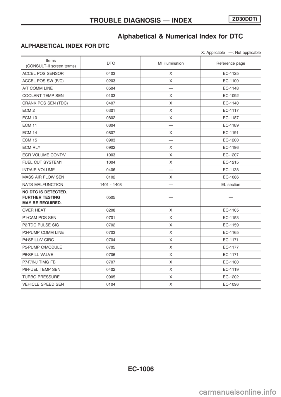
Alphabetical & Numerical Index for DTC
ALPHABETICAL INDEX FOR DTC
X: Applicable Ð: Not applicable
Items
(CONSULT-II screen terms)DTC MI illumination Reference page
ACCEL POS SENSOR 0403 X EC-1125
ACCEL POS SW (F/C) 0203 X EC-1100
A/T COMM LINE 0504 Ð EC-1148
COOLANT TEMP SEN 0103 X EC-1092
CRANK POS SEN (TDC) 0407 X EC-1140
ECM 2 0301 X EC-1117
ECM 10 0802 X EC-1187
ECM 11 0804 Ð EC-1189
ECM 14 0807 X EC-1191
ECM 15 0903 Ð EC-1200
ECM RLY 0902 X EC-1196
EGR VOLUME CONT/V 1003 X EC-1207
FUEL CUT SYSTEM1 1004 X EC-1215
INT/AIR VOLUME 0406 Ð EC-1138
MASS AIR FLOW SEN 0102 X EC-1086
NATS MALFUNCTION 1401 - 1408 Ð EL section
NO DTC IS DETECTED.
FURTHER TESTING
MAY BE REQUIRED.0505 Ð Ð
OVER HEAT 0208 X EC-1105
P1zCAM POS SEN 0701 X EC-1153
P2zTDC PULSE SIG 0702 X EC-1159
P3zPUMP COMM LINE 0703 X EC-1165
P4zSPILL/V CIRC 0704 X EC-1171
P5zPUMP C/MODULE 0705 X EC-1177
P6zSPILL VALVE 0706 X EC-1171
P7zF/INJ TIMG FB 0707 X EC-1180
P9zFUEL TEMP SEN 0402 X EC-1119
TURBO PRESSURE 0905 X EC-1202
VEHICLE SPEED SEN 0104 X EC-1096
TROUBLE DIAGNOSIS Ð INDEXZD30DDTi
EC-1006
Page 240 of 1033
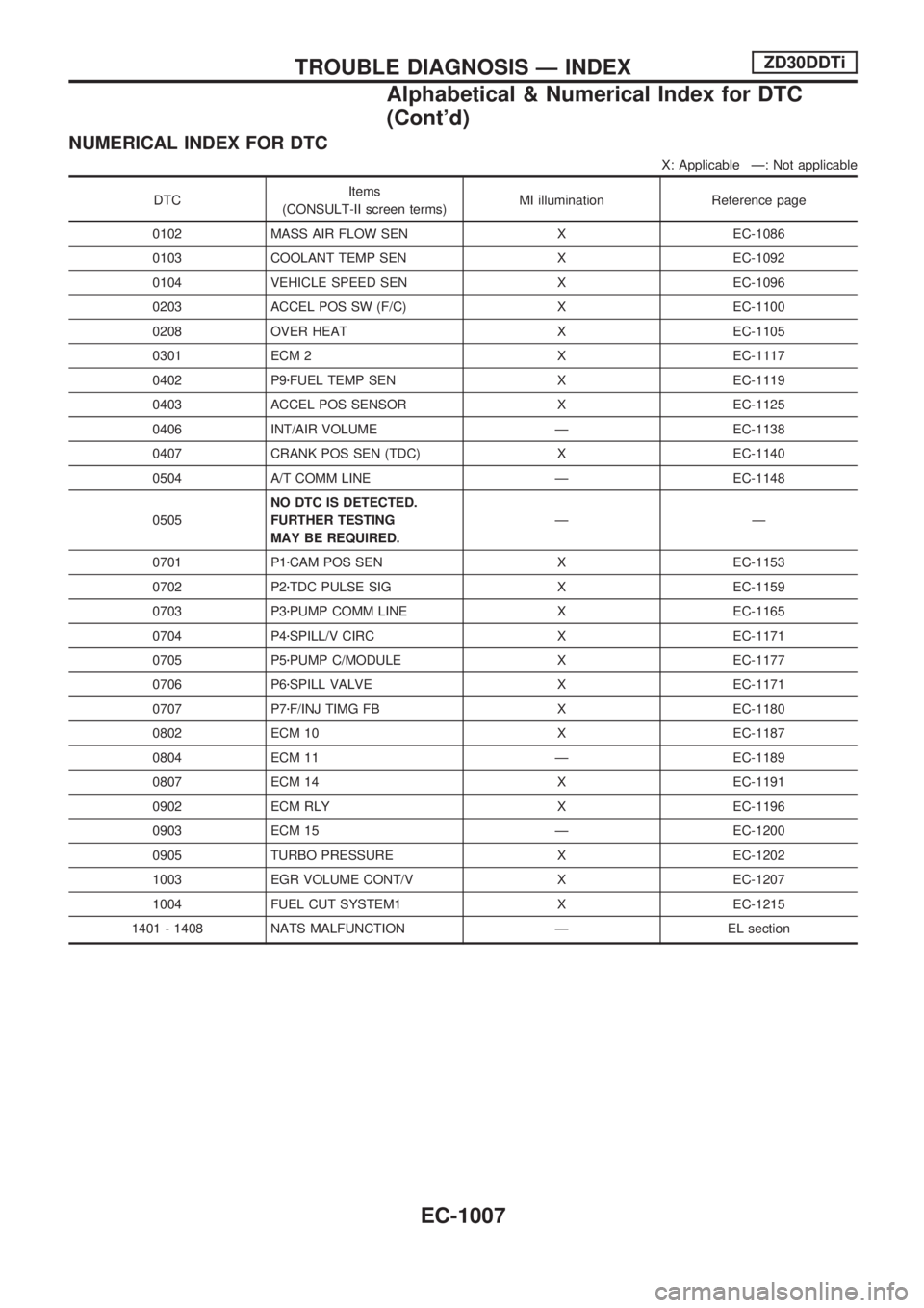
NUMERICAL INDEX FOR DTC
X: Applicable Ð: Not applicable
DTCItems
(CONSULT-II screen terms)MI illumination Reference page
0102 MASS AIR FLOW SEN X EC-1086
0103 COOLANT TEMP SEN X EC-1092
0104 VEHICLE SPEED SEN X EC-1096
0203 ACCEL POS SW (F/C) X EC-1100
0208 OVER HEAT X EC-1105
0301 ECM 2 X EC-1117
0402 P9zFUEL TEMP SEN X EC-1119
0403 ACCEL POS SENSOR X EC-1125
0406 INT/AIR VOLUME Ð EC-1138
0407 CRANK POS SEN (TDC) X EC-1140
0504 A/T COMM LINE Ð EC-1148
0505NO DTC IS DETECTED.
FURTHER TESTING
MAY BE REQUIRED.ÐÐ
0701 P1zCAM POS SEN X EC-1153
0702 P2zTDC PULSE SIG X EC-1159
0703 P3zPUMP COMM LINE X EC-1165
0704 P4zSPILL/V CIRC X EC-1171
0705 P5zPUMP C/MODULE X EC-1177
0706 P6zSPILL VALVE X EC-1171
0707 P7zF/INJ TIMG FB X EC-1180
0802 ECM 10 X EC-1187
0804 ECM 11 Ð EC-1189
0807 ECM 14 X EC-1191
0902 ECM RLY X EC-1196
0903 ECM 15 Ð EC-1200
0905 TURBO PRESSURE X EC-1202
1003 EGR VOLUME CONT/V X EC-1207
1004 FUEL CUT SYSTEM1 X EC-1215
1401 - 1408 NATS MALFUNCTION Ð EL section
TROUBLE DIAGNOSIS Ð INDEXZD30DDTi
Alphabetical & Numerical Index for DTC
(Cont'd)
EC-1007
Page 243 of 1033
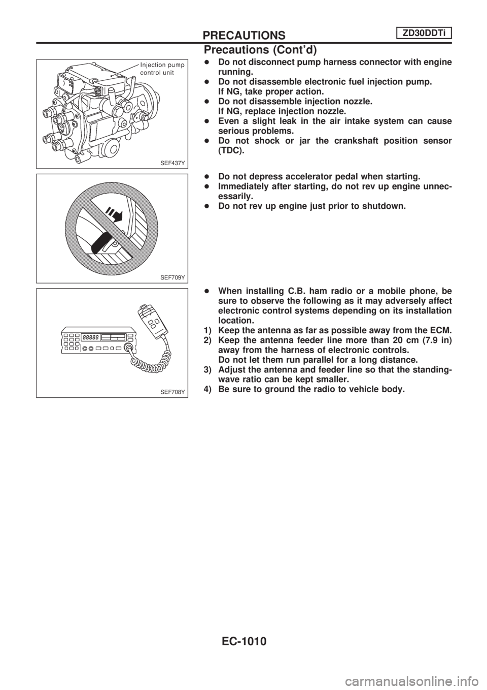
+Do not disconnect pump harness connector with engine
running.
+Do not disassemble electronic fuel injection pump.
If NG, take proper action.
+Do not disassemble injection nozzle.
If NG, replace injection nozzle.
+Even a slight leak in the air intake system can cause
serious problems.
+Do not shock or jar the crankshaft position sensor
(TDC).
+Do not depress accelerator pedal when starting.
+Immediately after starting, do not rev up engine unnec-
essarily.
+Do not rev up engine just prior to shutdown.
+When installing C.B. ham radio or a mobile phone, be
sure to observe the following as it may adversely affect
electronic control systems depending on its installation
location.
1) Keep the antenna as far as possible away from the ECM.
2) Keep the antenna feeder line more than 20 cm (7.9 in)
away from the harness of electronic controls.
Do not let them run parallel for a long distance.
3) Adjust the antenna and feeder line so that the standing-
wave ratio can be kept smaller.
4) Be sure to ground the radio to vehicle body.
SEF437Y
SEF709Y
SEF708Y
PRECAUTIONSZD30DDTi
Precautions (Cont'd)
EC-1010
Page 251 of 1033
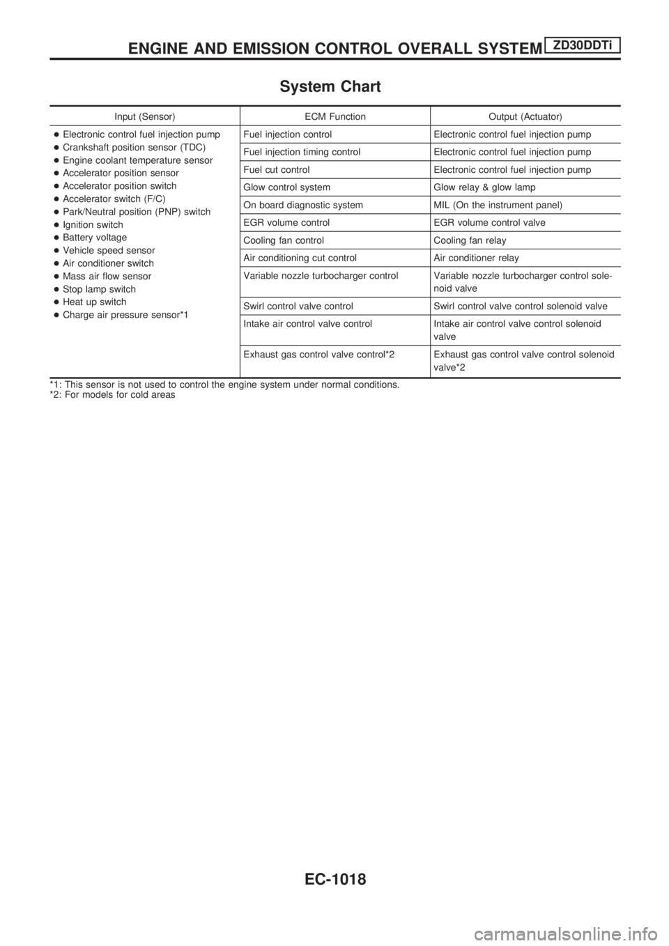
System Chart
Input (Sensor) ECM Function Output (Actuator)
+Electronic control fuel injection pump
+Crankshaft position sensor (TDC)
+Engine coolant temperature sensor
+Accelerator position sensor
+Accelerator position switch
+Accelerator switch (F/C)
+Park/Neutral position (PNP) switch
+Ignition switch
+Battery voltage
+Vehicle speed sensor
+Air conditioner switch
+Mass air flow sensor
+Stop lamp switch
+Heat up switch
+Charge air pressure sensor*1Fuel injection control Electronic control fuel injection pump
Fuel injection timing control Electronic control fuel injection pump
Fuel cut control Electronic control fuel injection pump
Glow control system Glow relay & glow lamp
On board diagnostic system MIL (On the instrument panel)
EGR volume control EGR volume control valve
Cooling fan control Cooling fan relay
Air conditioning cut control Air conditioner relay
Variable nozzle turbocharger control Variable nozzle turbocharger control sole-
noid valve
Swirl control valve control Swirl control valve control solenoid valve
Intake air control valve control Intake air control valve control solenoid
valve
Exhaust gas control valve control*2 Exhaust gas control valve control solenoid
valve*2
*1: This sensor is not used to control the engine system under normal conditions.
*2: For models for cold areas
ENGINE AND EMISSION CONTROL OVERALL SYSTEMZD30DDTi
EC-1018
Page 252 of 1033
Fuel Injection Control System
DESCRIPTION
System description
Three types of fuel injection control are provided to accommodate engine operating conditions; normal
control, idle control and start control. The ECM determines the appropriate fuel injection control. Under each
control, the amount of fuel injected is compensated to improve engine performance.
Pulse signals are exchanged between ECM and electronic control fuel injection pump (control unit is built-
in). The fuel injection pump control unit performs duty control on the spill valve (built into the fuel injection
pump) according to the input signals to compensate the amount of fuel injected to the preset value.
Start control
Input/output signal chart
Sensor Input Signal to ECM ECM Function Actuator
Engine coolant temperature sensor Engine coolant temperature
Fuel injection con-
trol (start control)Electronic control fuel injec-
tion pump Crankshaft position sensor (TDC) Engine speed
Ignition switch Start signal
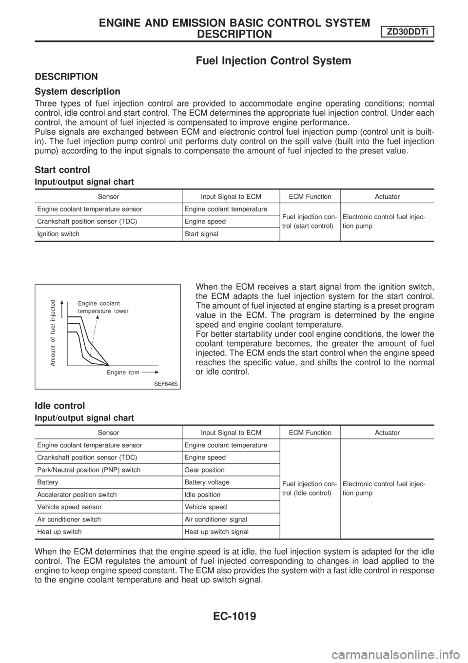
When the ECM receives a start signal from the ignition switch,
the ECM adapts the fuel injection system for the start control.
The amount of fuel injected at engine starting is a preset program
value in the ECM. The program is determined by the engine
speed and engine coolant temperature.
For better startability under cool engine conditions, the lower the
coolant temperature becomes, the greater the amount of fuel
injected. The ECM ends the start control when the engine speed
reaches the specific value, and shifts the control to the normal
or idle control.
Idle control
Input/output signal chart
Sensor Input Signal to ECM ECM Function Actuator
Engine coolant temperature sensor Engine coolant temperature
Fuel injection con-
trol (Idle control)Electronic control fuel injec-
tion pump Crankshaft position sensor (TDC) Engine speed
Park/Neutral position (PNP) switch Gear position
Battery Battery voltage
Accelerator position switch Idle position
Vehicle speed sensor Vehicle speed
Air conditioner switch Air conditioner signal
Heat up switch Heat up switch signal
When the ECM determines that the engine speed is at idle, the fuel injection system is adapted for the idle
control. The ECM regulates the amount of fuel injected corresponding to changes in load applied to the
engine to keep engine speed constant. The ECM also provides the system with a fast idle control in response
to the engine coolant temperature and heat up switch signal.
SEF648S
ENGINE AND EMISSION BASIC CONTROL SYSTEM
DESCRIPTIONZD30DDTi
EC-1019