2000 NISSAN PATROL checking oil
[x] Cancel search: checking oilPage 5 of 1033
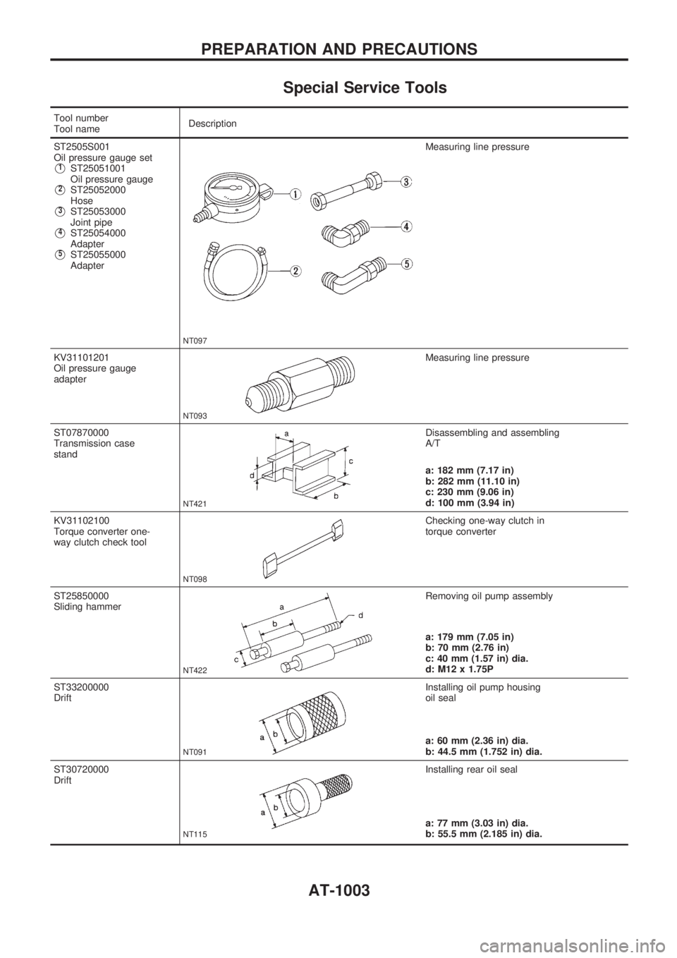
Special Service Tools
Tool number
Tool nameDescription
ST2505S001
Oil pressure gauge set
V1ST25051001
Oil pressure gauge
V2ST25052000
Hose
V3ST25053000
Joint pipe
V4ST25054000
Adapter
V5ST25055000
Adapter
NT097
Measuring line pressure
KV31101201
Oil pressure gauge
adapter
NT093
Measuring line pressure
ST07870000
Transmission case
stand
NT421
Disassembling and assembling
A/T
a: 182 mm (7.17 in)
b: 282 mm (11.10 in)
c: 230 mm (9.06 in)
d: 100 mm (3.94 in)
KV31102100
Torque converter one-
way clutch check tool
NT098
Checking one-way clutch in
torque converter
ST25850000
Sliding hammer
NT422
Removing oil pump assembly
a: 179 mm (7.05 in)
b: 70 mm (2.76 in)
c: 40 mm (1.57 in) dia.
d: M12 x 1.75P
ST33200000
Drift
NT091
Installing oil pump housing
oil seal
a: 60 mm (2.36 in) dia.
b: 44.5 mm (1.752 in) dia.
ST30720000
Drift
NT115
Installing rear oil seal
a: 77 mm (3.03 in) dia.
b: 55.5 mm (2.185 in) dia.
PREPARATION AND PRECAUTIONS
AT-1003
Page 43 of 1033
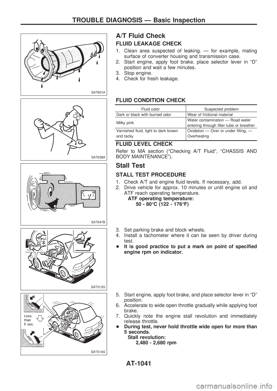
A/T Fluid Check
FLUID LEAKAGE CHECK
1. Clean area suspected of leaking. Ð for example, mating
surface of converter housing and transmission case.
2. Start engine, apply foot brake, place selector lever in ªDº
position and wait a few minutes.
3. Stop engine.
4. Check for fresh leakage.
FLUID CONDITION CHECK
Fluid color Suspected problem
Dark or black with burned odor Wear of frictional material
Milky pinkWater contamination Ð Road water
entering through filler tube or breather
Varnished fluid, light to dark brown
and tackyOxidation Ð Over or under filling, Ð
Overheating
FLUID LEVEL CHECK
Refer to MA section (ªChecking A/T Fluidº, ªCHASSIS AND
BODY MAINTENANCEº).
Stall Test
STALL TEST PROCEDURE
1. Check A/T and engine fluid levels. If necessary, add.
2. Drive vehicle for approx. 10 minutes or until engine oil and
ATF reach operating temperature.
ATF operating temperature:
50 - 80ÉC (122 - 176ÉF)
3. Set parking brake and block wheels.
4. Install a tachometer where it can be seen by driver during
test.
+It is good practice to put a mark on point of specified
engine rpm on indicator.
5. Start engine, apply foot brake, and place selector lever in ªDº
position.
6. Accelerate to wide open throttle gradually while applying foot
brake.
7. Quickly note the engine stall revolution and immediately
release throttle.
+During test, never hold throttle wide open for more than
5 seconds.
Stall revolution:
2,480 - 2,680 rpm
SAT801A
SAT638A
SAT647B
SAT513G
SAT514G
TROUBLE DIAGNOSIS Ð Basic Inspection
AT-1041
Page 260 of 1033
REMOVAL
1. Remove the following:
+Engine coolant draining
+Charge air cooler
+Air inlet pipe
+Throttle body
+Rocker cover
+Oil level gauge guide
+EGR guide tube
+EGR volume control solenoid valve
+Fuel hose
+Injection tube
+Radiator upper hose
+Radiator shroud
+Cooling fan
+Drive belt
+Vacuum pipe
+Vacuum pump
2. Move the power steering pump.
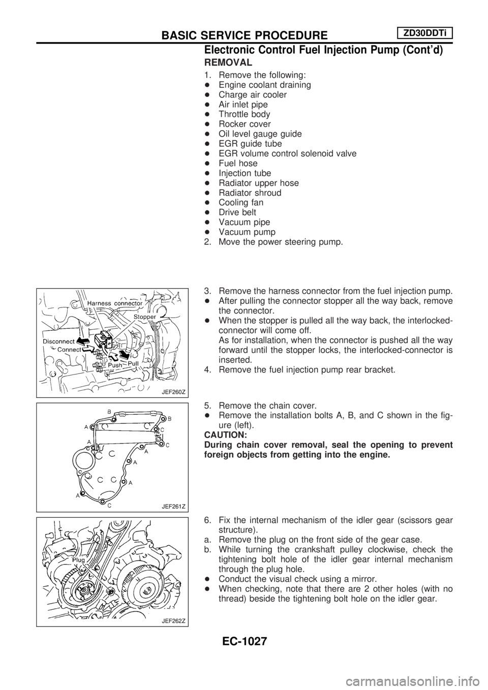
3. Remove the harness connector from the fuel injection pump.
+After pulling the connector stopper all the way back, remove
the connector.
+When the stopper is pulled all the way back, the interlocked-
connector will come off.
As for installation, when the connector is pushed all the way
forward until the stopper locks, the interlocked-connector is
inserted.
4. Remove the fuel injection pump rear bracket.
5. Remove the chain cover.
+Remove the installation bolts A, B, and C shown in the fig-
ure (left).
CAUTION:
During chain cover removal, seal the opening to prevent
foreign objects from getting into the engine.
6. Fix the internal mechanism of the idler gear (scissors gear
structure).
a. Remove the plug on the front side of the gear case.
b. While turning the crankshaft pulley clockwise, check the
tightening bolt hole of the idler gear internal mechanism
through the plug hole.
+Conduct the visual check using a mirror.
+When checking, note that there are 2 other holes (with no
thread) beside the tightening bolt hole on the idler gear.
JEF260Z
JEF261Z
JEF262Z
BASIC SERVICE PROCEDUREZD30DDTi
Electronic Control Fuel Injection Pump (Cont'd)
EC-1027
Page 743 of 1033
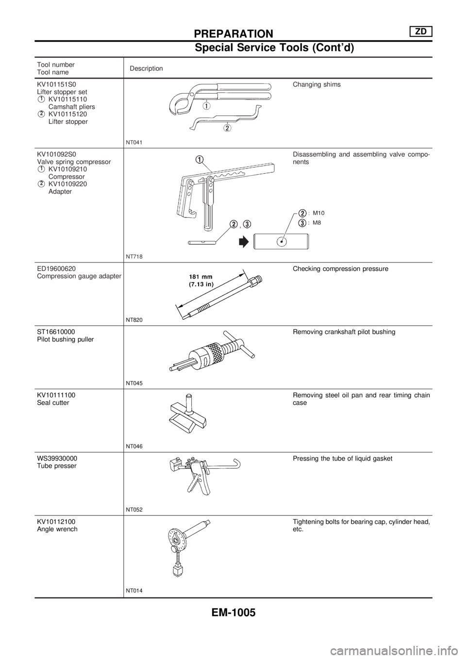
Tool number
Tool nameDescription
KV101151S0
Lifter stopper set
V1KV10115110
Camshaft pliers
V2KV10115120
Lifter stopper
NT041
Changing shims
KV101092S0
Valve spring compressor
V1KV10109210
Compressor
V2KV10109220
Adapter
NT718
Disassembling and assembling valve compo-
nents
ED19600620
Compression gauge adapter
NT820
Checking compression pressure
ST16610000
Pilot bushing puller
NT045
Removing crankshaft pilot bushing
KV10111100
Seal cutter
NT046
Removing steel oil pan and rear timing chain
case
WS39930000
Tube presser
NT052
Pressing the tube of liquid gasket
KV10112100
Angle wrench
NT014
Tightening bolts for bearing cap, cylinder head,
etc.
PREPARATIONZD
Special Service Tools (Cont'd)
EM-1005
Page 747 of 1033
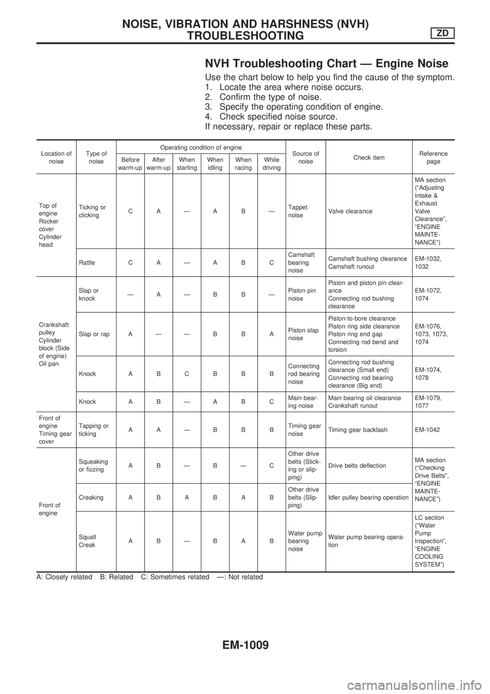
NVH Troubleshooting Chart Ð Engine Noise
Use the chart below to help you find the cause of the symptom.
1. Locate the area where noise occurs.
2. Confirm the type of noise.
3. Specify the operating condition of engine.
4. Check specified noise source.
If necessary, repair or replace these parts.
Location of
noiseType of
noiseOperating condition of engine
Source of
noiseCheck itemReference
page Before
warm-upAfter
warm-upWhen
startingWhen
idlingWhen
racingWhile
driving
Top of
engine
Rocker
cover
Cylinder
headTicking or
clickingCAÐABÐTappet
noiseValve clearanceMA section
(ªAdjusting
Intake &
Exhaust
Valve
Clearanceº,
ªENGINE
MAINTE-
NANCEº)
Rattle C A Ð A B CCamshaft
bearing
noiseCamshaft bushing clearance
Camshaft runoutEM-1032,
1032
Crankshaft
pulley
Cylinder
block (Side
of engine)
Oil panSlap or
knockÐAÐB BÐPiston pin
noisePiston and piston pin clear-
ance
Connecting rod bushing
clearanceEM-1072,
1074
Slap or rap A Ð Ð B B APiston slap
noisePiston-to-bore clearance
Piston ring side clearance
Piston ring end gap
Connecting rod bend and
torsionEM-1076,
1073, 1073,
1074
Knock A B C B B BConnecting
rod bearing
noiseConnecting rod bushing
clearance (Small end)
Connecting rod bearing
clearance (Big end)EM-1074,
1078
Knock A B Ð A B CMain bear-
ing noiseMain bearing oil clearance
Crankshaft runoutEM-1079,
1077
Front of
engine
Timing gear
coverTapping or
tickingAAÐBBBTiming gear
noiseTiming gear backlash EM-1042
Front of
engineSqueaking
or fizzingABÐBÐCOther drive
belts (Stick-
ing or slip-
ping)Drive belts deflectionMA section
(ªChecking
Drive Beltsº,
ªENGINE
MAINTE-
NANCEº) CreakingABABABOther drive
belts (Slip-
ping)Idler pulley bearing operation
Squall
CreakABÐBABWater pump
bearing
noiseWater pump bearing opera-
tionLC section
(ªWater
Pump
Inspectionº,
ªENGINE
COOLING
SYSTEMº)
A: Closely related B: Related C: Sometimes related Ð: Not related
NOISE, VIBRATION AND HARSHNESS (NVH)
TROUBLESHOOTINGZD
EM-1009
Page 755 of 1033
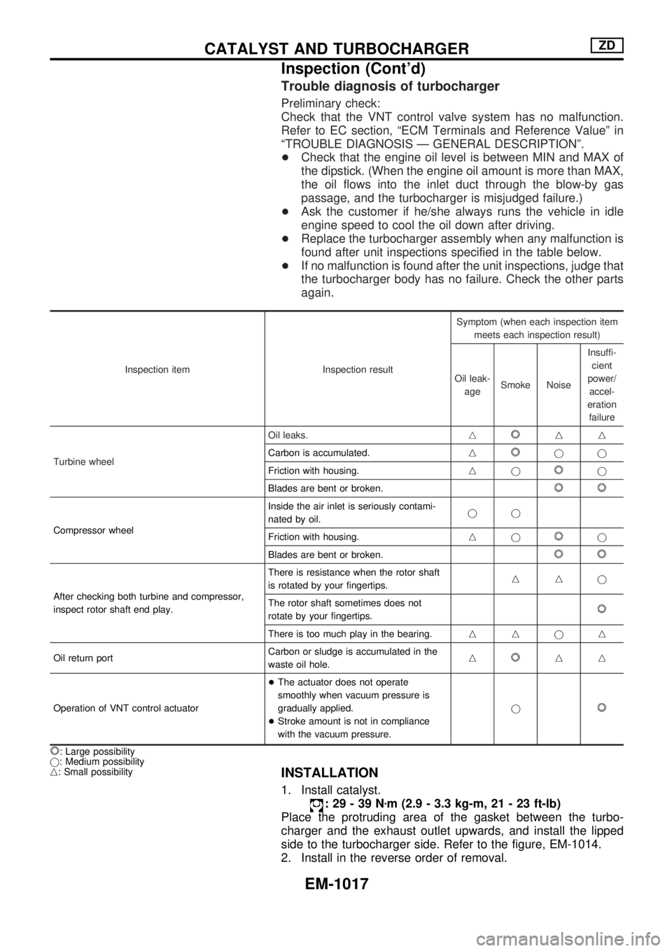
Trouble diagnosis of turbocharger
Preliminary check:
Check that the VNT control valve system has no malfunction.
Refer to EC section, ªECM Terminals and Reference Valueº in
ªTROUBLE DIAGNOSIS Ð GENERAL DESCRIPTIONº.
+Check that the engine oil level is between MIN and MAX of
the dipstick. (When the engine oil amount is more than MAX,
the oil flows into the inlet duct through the blow-by gas
passage, and the turbocharger is misjudged failure.)
+Ask the customer if he/she always runs the vehicle in idle
engine speed to cool the oil down after driving.
+Replace the turbocharger assembly when any malfunction is
found after unit inspections specified in the table below.
+If no malfunction is found after the unit inspections, judge that
the turbocharger body has no failure. Check the other parts
again.
Inspection item Inspection resultSymptom (when each inspection item
meets each inspection result)
Oil leak-
ageSmoke NoiseInsuffi-
cient
power/
accel-
eration
failure
Turbine wheelOil leaks.n
nn
Carbon is accumulated.n
jj
Friction with housing.nj
j
Blades are bent or broken.
Compressor wheelInside the air inlet is seriously contami-
nated by oil.jj
Friction with housing.njj
Blades are bent or broken.
After checking both turbine and compressor,
inspect rotor shaft end play.There is resistance when the rotor shaft
is rotated by your fingertips.nnj
The rotor shaft sometimes does not
rotate by your fingertips.
There is too much play in the bearing.nnjn
Oil return portCarbon or sludge is accumulated in the
waste oil hole.n
nn
Operation of VNT control actuator+The actuator does not operate
smoothly when vacuum pressure is
gradually applied.
+Stroke amount is not in compliance
with the vacuum pressure.j
: Large possibility
j: Medium possibility
n: Small possibility
INSTALLATION
1. Install catalyst.
:29-39Nzm (2.9 - 3.3 kg-m, 21 - 23 ft-lb)
Place the protruding area of the gasket between the turbo-
charger and the exhaust outlet upwards, and install the lipped
side to the turbocharger side. Refer to the figure, EM-1014.
2. Install in the reverse order of removal.
CATALYST AND TURBOCHARGERZD
Inspection (Cont'd)
EM-1017
Page 899 of 1033
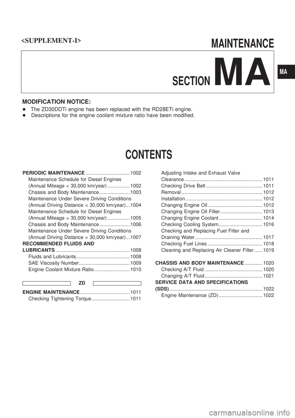
MAINTENANCE
SECTION
MA
MODIFICATION NOTICE:
+ The ZD30DDTi engine has been replaced with the RD28ETi engine.
+ Descriptions for the engine coolant mixture ratio have been modified.
CONTENTS
PERIODIC MAINTENANCE ................................ 1002
Maintenance Schedule for Diesel Engines
(Annual Mileage < 30,000 km/year) ................ 1002
Chassis and Body Maintenance ...................... 1003
Maintenance Under Severe Driving Conditions
(Annual Driving Distance < 30,000 km/year)... 1004
Maintenance Schedule for Diesel Engines
(Annual Mileage > 30,000 km/year) ................ 1005
Chassis and Body Maintenance ...................... 1006
Maintenance Under Severe Driving Conditions
(AnnualDrivingDistance>30,000km/year)...1007
RECOMMENDED FLUIDS AND
LUBRICANTS ...................................................... 1008
Fluids and Lubricants....................................... 1008
SAE Viscosity Number..................................... 1009
Engine Coolant Mixture Ratio .......................... 1010
ZD
ENGINE MAINTENANCE .................................... 1011
Checking Tightening Torque............................ 1011 Adjusting Intake and Exhaust Valve
Clearance ......................................................... 1011
Checking Drive Belt ......................................... 1011
Removal ........................................................... 1012
Installation ........................................................ 1012
Changing Engine Oil ........................................ 1012
Changing Engine Oil Filter............................... 1013
Changing Engine Coolant ................................ 1014
Checking Cooling System................................ 1016
Checking and Replacing Fuel Filter and
Draining Water ................................................. 1017
Checking Fuel Lines ........................................ 1018
Cleaning and Replacing Air Cleaner Filter ...... 1019
CHASSIS AND BODY MAINTENANCE ............. 1020
Checking A/T Fluid .......................................... 1020
Changing A/T Fluid .......................................... 1021
SERVICE DATA AND SPECIFICATIONS
(SDS) .................................................................... 1022
Engine Maintenance (ZD) ................................ 1022
MA
Page 900 of 1033
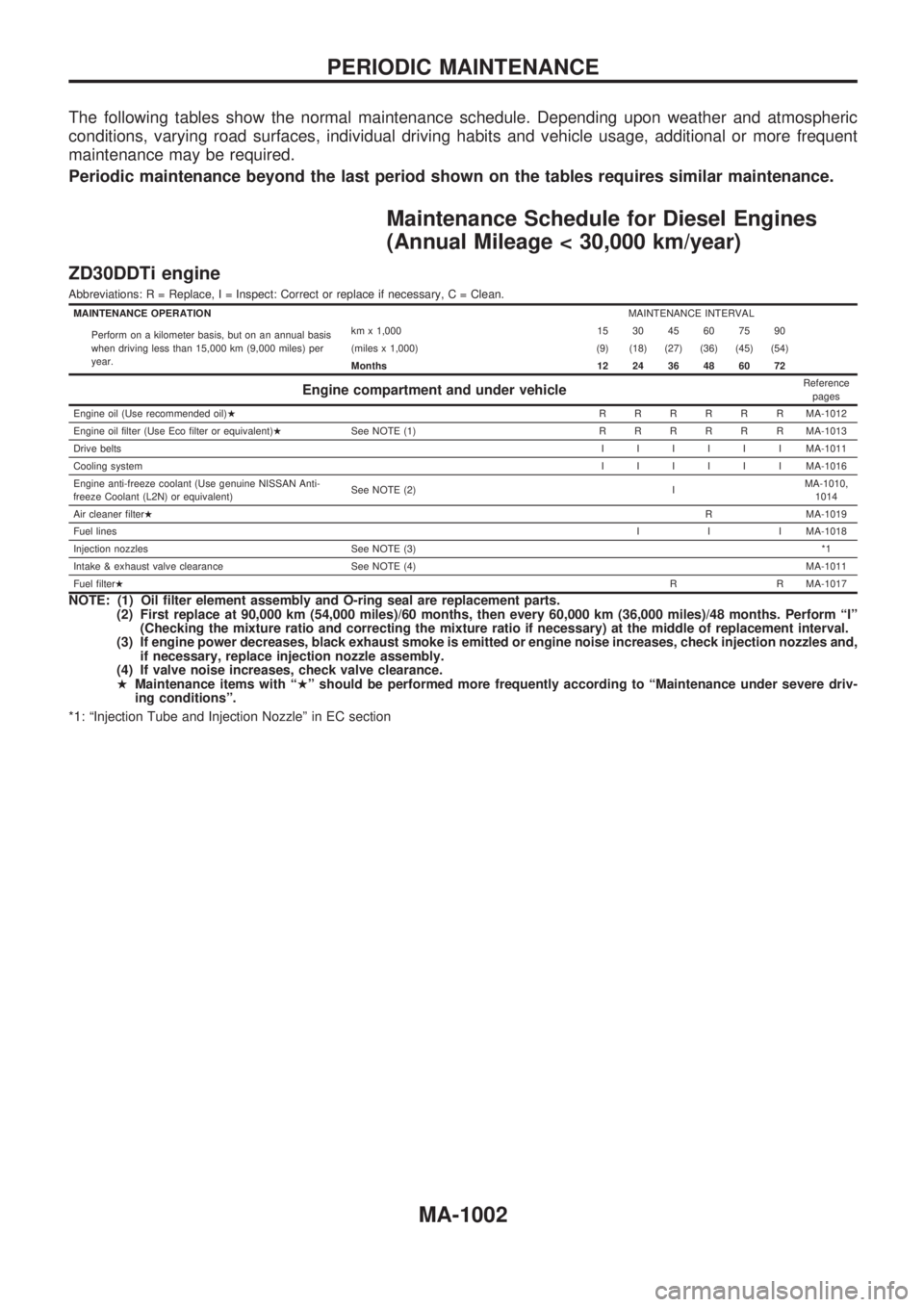
The following tables show the normal maintenance schedule. Depending upon weather and atmospheric
conditions, varying road surfaces, individual driving habits and vehicle usage, additional or more frequent
maintenance may be required.
Periodic maintenance beyond the last period shown on the tables requires similar maintenance.
Maintenance Schedule for Diesel Engines
(Annual Mileage < 30,000 km/year)
ZD30DDTi engine
Abbreviations: R = Replace, I = Inspect: Correct or replace if necessary, C = Clean.
MAINTENANCE OPERATIONMAINTENANCE INTERVAL
Perform on a kilometer basis, but on an annual basis
when driving less than 15,000 km (9,000 miles) per
year.km x 1,000 15 30 45 60 75 90
(miles x 1,000) (9) (18) (27) (36) (45) (54)
Months 12 24 36 48 60 72
Engine compartment and under vehicleReference
pages
Engine oil (Use recommended oil)HRRRRRRMA-1012
Engine oil filter (Use Eco filter or equivalent)HSee NOTE (1)RRRRRRMA-1013
Drive beltsIIIIIIMA-1011
Cooling systemIIIIIIMA-1016
Engine anti-freeze coolant (Use genuine NISSAN Anti-
freeze Coolant (L2N) or equivalent)See NOTE (2) IMA-1010,
1014
Air cleaner filterHR MA-1019
Fuel linesI I I MA-1018
Injection nozzles See NOTE (3)*1
Intake & exhaust valve clearance See NOTE (4)MA-1011
Fuel filterHR R MA-1017
NOTE: (1) Oil filter element assembly and O-ring seal are replacement parts.
(2) First replace at 90,000 km (54,000 miles)/60 months, then every 60,000 km (36,000 miles)/48 months. Perform ªIº
(Checking the mixture ratio and correcting the mixture ratio if necessary) at the middle of replacement interval.
(3) If engine power decreases, black exhaust smoke is emitted or engine noise increases, check injection nozzles and,
if necessary, replace injection nozzle assembly.
(4) If valve noise increases, check valve clearance.
HMaintenance items with ªHº should be performed more frequently according to ªMaintenance under severe driv-
ing conditionsº.
*1: ªInjection Tube and Injection Nozzleº in EC section
PERIODIC MAINTENANCE
MA-1002