2000 NISSAN PATROL cruise control
[x] Cancel search: cruise controlPage 37 of 1033
![NISSAN PATROL 2000 Electronic Repair Manual Item DisplayMonitor item
Description Remarks TCM
input
signalsMain
signals
1 position switch 1 POSITION SW
[ON/OFF] X Ð+ON/OFF status, computed from
signal of 1 position SW, is dis-
played.
ASCD-crui NISSAN PATROL 2000 Electronic Repair Manual Item DisplayMonitor item
Description Remarks TCM
input
signalsMain
signals
1 position switch 1 POSITION SW
[ON/OFF] X Ð+ON/OFF status, computed from
signal of 1 position SW, is dis-
played.
ASCD-crui](/manual-img/5/57367/w960_57367-36.png)
Item DisplayMonitor item
Description Remarks TCM
input
signalsMain
signals
1 position switch 1 POSITION SW
[ON/OFF] X Ð+ON/OFF status, computed from
signal of 1 position SW, is dis-
played.
ASCD-cruise signal ASCD-CRUISE
[ON/OFF]
XÐ+Status of ASCD cruise signal is
displayed.
ON ... Cruising state
OFF ... Normal running state+This is displayed even when no
ASCD is mounted.
ASCD-OD cut signal ASCD-OD CUT
[ON/OFF]
XÐ+Status of ASCDzOD release
signal is displayed.
ON ... OD released
OFF ... OD not released+This is displayed even when no
ASCD is mounted.
Kickdown switch KICKDOWN SW
[ON/OFF] X Ð+ON/OFF status, computed from
signal of kickdown SW, is dis-
played.+This is displayed even when no
kickdown switch is equipped.
A/T mode switch POWER SHIFT SW
[ON/OFF] X Ð+ON/OFF state computed from
signal of POWER shift SW is
displayed.
Closed throttle position switch CLOSED THL/SW
[ON/OFF]
XÐ+ON/OFF status, computed from
signal of closed throttle (accel-
erator) position SW, is dis-
played.
Wide open throttle position switch W/O THRL/P-SW
[ON/OFF]
XÐ+ON/OFF status, computed from
signal of wide open throttle
(accelerator) position SW, is
displayed.
A/T mode switch HOLD SW
[ON/OFF] X Ð+ON/OFF status, computed from
signal of HOLD shift SW, is
displayed.
Gear position GEAR
ÐX+Gear position data used for
computation by TCM, is dis-
played.
Selector lever position SLCT LVR POSI
ÐX+Selector lever position data,
used for computation by TCM,
is displayed.+A specific value used for con-
trol is displayed if fail-safe is
activated due to error.
Vehicle speed VEHICLE SPEED
[km/h] or [mph] Ð X+Vehicle speed data, used for
computation by TCM, is dis-
played.
Accelerator position THROTTLE POSI
[/8] Ð X+Throttle (accelerator) position
data, used for computation by
TCM, is displayed.+A specific value used for con-
trol is displayed if fail-safe is
activated due to error.
Line pressure duty LINE PRES DTY
[%]
ÐX+Control value of line pressure
solenoid valve, computed by
TCM from each input signal, is
displayed.
Torque converter clutch solenoid
valve dutyTCC S/V DUTY
[%]
ÐX+Control value of torque con-
verter clutch solenoid valve,
computed by TCM from each
input signal, is displayed.
Shift solenoid valve A SHIFT S/V A
[ON/OFF]
ÐX+Control value of shift solenoid
valve A, computed by TCM
from each input signal, is dis-
played.Control value of solenoid is dis-
played even if solenoid circuit is
disconnected.
The ªOFFº signal is displayed if
solenoid circuit is shorted.
Shift solenoid valve B SHIFT S/V B
[ON/OFF]
ÐX+Control value of shift solenoid
valve B, computed by TCM
from each input signal, is dis-
played.
Overrun clutch solenoid valve OVERRUN/C S/V
[ON/OFF]
ÐX+Control value of overrun clutch
solenoid valve computed by
TCM from each input signal is
displayed.
Self-diagnosis display lamp
(SPORT indicator lamp)SELF-D DP LMP
[ON/OFF]ÐX+Control status of SPORT indi-
cator lamp is displayed.
X: Applicable
Ð: Not applicable
ON BOARD DIAGNOSTIC SYSTEM DESCRIPTION
Diagnosis by CONSULT-II (Cont'd)
AT-1035
Page 40 of 1033
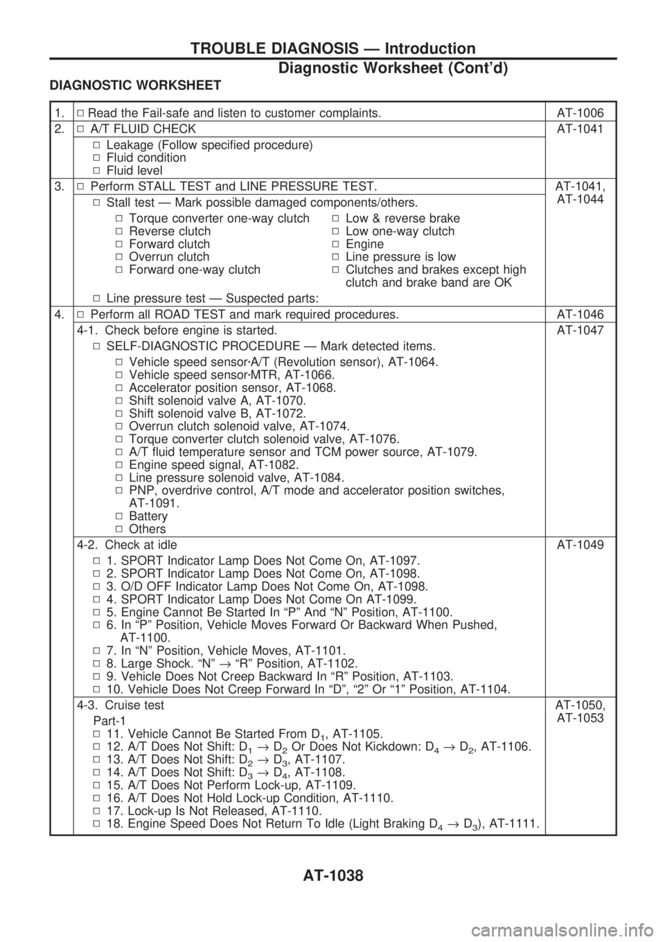
DIAGNOSTIC WORKSHEET
1.NRead the Fail-safe and listen to customer complaints. AT-1006
2.NA/T FLUID CHECK AT-1041
NLeakage (Follow specified procedure)
NFluid condition
NFluid level
3.NPerform STALL TEST and LINE PRESSURE TEST. AT-1041,
AT-1044
NStall test Ð Mark possible damaged components/others.
NTorque converter one-way clutch
NReverse clutch
NForward clutch
NOverrun clutch
NForward one-way clutchNLow & reverse brake
NLow one-way clutch
NEngine
NLine pressure is low
NClutches and brakes except high
clutch and brake band are OK
NLine pressure test Ð Suspected parts:
4.NPerform all ROAD TEST and mark required procedures. AT-1046
4-1. Check before engine is started. AT-1047
NSELF-DIAGNOSTIC PROCEDURE Ð Mark detected items.
NVehicle speed sensorzA/T (Revolution sensor), AT-1064.
NVehicle speed sensorzMTR, AT-1066.
NAccelerator position sensor, AT-1068.
NShift solenoid valve A, AT-1070.
NShift solenoid valve B, AT-1072.
NOverrun clutch solenoid valve, AT-1074.
NTorque converter clutch solenoid valve, AT-1076.
NA/T fluid temperature sensor and TCM power source, AT-1079.
NEngine speed signal, AT-1082.
NLine pressure solenoid valve, AT-1084.
NPNP, overdrive control, A/T mode and accelerator position switches,
AT-1091.
NBattery
NOthers
4-2. Check at idle AT-1049
N1. SPORT Indicator Lamp Does Not Come On, AT-1097.
N2. SPORT Indicator Lamp Does Not Come On, AT-1098.
N3. O/D OFF Indicator Lamp Does Not Come On, AT-1098.
N4. SPORT Indicator Lamp Does Not Come On AT-1099.
N5. Engine Cannot Be Started In ªPº And ªNº Position, AT-1100.
N6. In ªPº Position, Vehicle Moves Forward Or Backward When Pushed,
AT-1100.
N7. In ªNº Position, Vehicle Moves, AT-1101.
N8. Large Shock. ªNº®ªRº Position, AT-1102.
N9. Vehicle Does Not Creep Backward In ªRº Position, AT-1103.
N10. Vehicle Does Not Creep Forward In ªDº, ª2º Or ª1º Position, AT-1104.
4-3. Cruise test AT-1050,
AT-1053
Part-1
N11. Vehicle Cannot Be Started From D
1, AT-1105.
N12. A/T Does Not Shift: D
1®D2Or Does Not Kickdown: D4®D2, AT-1106.
N13. A/T Does Not Shift: D
2®D3, AT-1107.
N14. A/T Does Not Shift: D
3®D4, AT-1108.
N15. A/T Does Not Perform Lock-up, AT-1109.
N16. A/T Does Not Hold Lock-up Condition, AT-1110.
N17. Lock-up Is Not Released, AT-1110.
N18. Engine Speed Does Not Return To Idle (Light Braking D
4®D3), AT-1111.
TROUBLE DIAGNOSIS Ð Introduction
Diagnostic Worksheet (Cont'd)
AT-1038
Page 55 of 1033
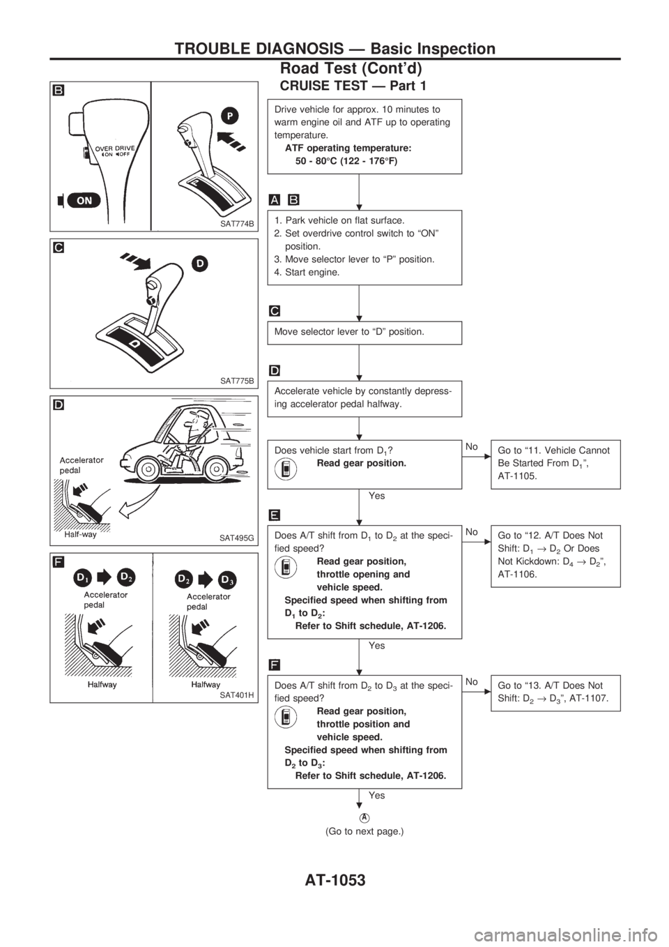
CRUISE TEST Ð Part 1
Drive vehicle for approx. 10 minutes to
warm engine oil and ATF up to operating
temperature.
ATF operating temperature:
50 - 80ÉC (122 - 176ÉF)
1. Park vehicle on flat surface.
2. Set overdrive control switch to ªONº
position.
3. Move selector lever to ªPº position.
4. Start engine.
Move selector lever to ªDº position.
Accelerate vehicle by constantly depress-
ing accelerator pedal halfway.
Does vehicle start from D1?
Read gear position.
Yes
cNo
Go to ª11. Vehicle Cannot
Be Started From D
1º,
AT-1105.
Does A/T shift from D1to D2at the speci-
fied speed?
Read gear position,
throttle opening and
vehicle speed.
Specified speed when shifting from
D
1to D2:
Refer to Shift schedule, AT-1206.
Yes
cNo
Go to ª12. A/T Does Not
Shift: D
1®D2Or Does
Not Kickdown: D
4®D2º,
AT-1106.
Does A/T shift from D2to D3at the speci-
fied speed?
Read gear position,
throttle position and
vehicle speed.
Specified speed when shifting from
D
2to D3:
Refer to Shift schedule, AT-1206.
Yes
cNo
Go to ª13. A/T Does Not
Shift: D
2®D3º, AT-1107.
VA
(Go to next page.)
SAT774B
SAT775B
SAT495G
SAT401H
.
.
.
.
.
.
.
TROUBLE DIAGNOSIS Ð Basic Inspection
Road Test (Cont'd)
AT-1053
Page 57 of 1033
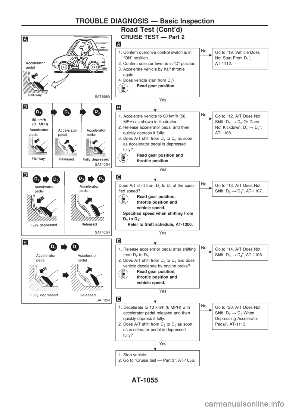
CRUISE TEST Ð Part 2
1. Confirm overdrive control switch is in
ªONº position.
2. Confirm selector lever is in ªDº position.
3. Accelerate vehicle by half throttle
again.
4. Does vehicle start from D
1?
Read gear position.
Yes
cNo
Go to ª19. Vehicle Does
Not Start From D
1º,
AT-1112.
1. Accelerate vehicle to 80 km/h (50
MPH) as shown in illustration.
2. Release accelerator pedal and then
quickly depress it fully.
3. Does A/T shift from D
4to D2as soon
as accelerator pedal is depressed
fully?
Read gear position and
throttle position.
Yes
cNo
Go to ª12. A/T Does Not
Shift: D
1®D2Or Does
Not Kickdown: D
4®D2º,
AT-1106.
Does A/T shift from D2to D3at the speci-
fied speed?
Read gear position,
throttle position and
vehicle speed.
Specified speed when shifting from
D
2to D3:
Refer to Shift schedule, AT-1206.
Yes
cNo
Go to ª13. A/T Does Not
Shift: D
2®D3º, AT-1107.
1. Release accelerator pedal after shifting
from D
2to D3.
2. Does A/T shift from D
3to D4and does
vehicle decelerate by engine brake?
Read gear position,
throttle position and
vehicle speed.
Yes
cNo
Go to ª14. A/T Does Not
Shift: D
3®D4º, AT-1108.
1. Decelerate to 10 km/h (6 MPH) with
accelerator pedal released and then
quickly depress it fully.
2. Does A/T shift from D
2to D1as soon
as accelerator pedal is depressed
fully?
Yes
cNo
Go to ª20. A/T Does Not
Shift: D
2®D1When
Depressing Accelerator
Pedalº, AT-1113.
1. Stop vehicle.
2. Go to ªCruise test Ð Part 3º, AT-1056.
SAT495G
SAT404H
SAT405H
SAT124I
.
.
.
.
.
TROUBLE DIAGNOSIS Ð Basic Inspection
Road Test (Cont'd)
AT-1055
Page 58 of 1033
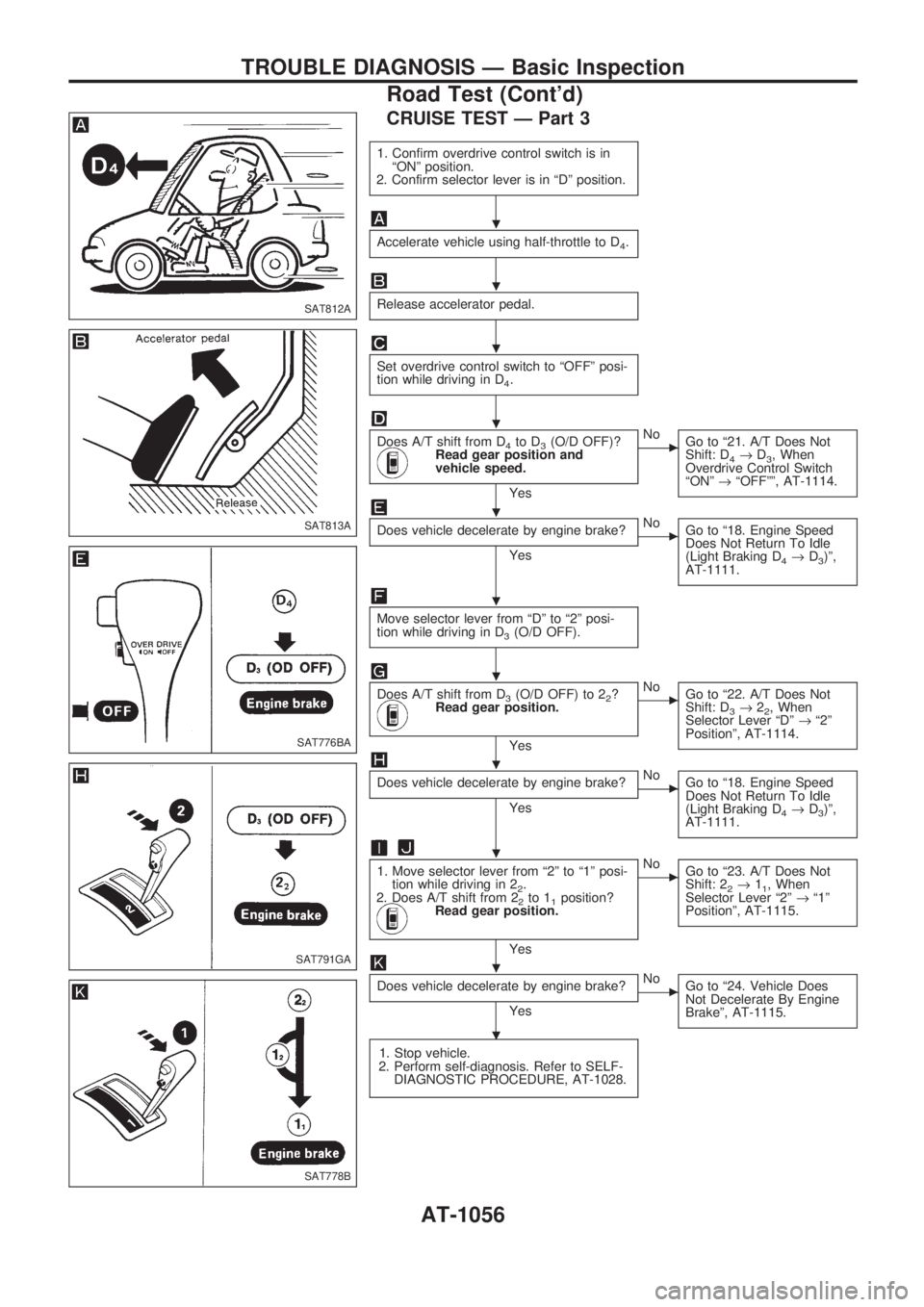
CRUISE TEST Ð Part 3
1. Confirm overdrive control switch is in
ªONº position.
2. Confirm selector lever is in ªDº position.
Accelerate vehicle using half-throttle to D4.
Release accelerator pedal.
Set overdrive control switch to ªOFFº posi-
tion while driving in D
4.
Does A/T shift from D4to D3(O/D OFF)?Read gear position and
vehicle speed.
Yes
cNo
Go to ª21. A/T Does Not
Shift: D
4®D3, When
Overdrive Control Switch
ªONº®ªOFFºº, AT-1114.
Does vehicle decelerate by engine brake?
Yes
cNo
Go to ª18. Engine Speed
Does Not Return To Idle
(Light Braking D
4®D3)º,
AT-1111.
Move selector lever from ªDº to ª2º posi-
tion while driving in D
3(O/D OFF).
Does A/T shift from D3(O/D OFF) to 22?Read gear position.
Yes
cNo
Go to ª22. A/T Does Not
Shift: D
3®22, When
Selector Lever ªDº®ª2º
Positionº, AT-1114.
Does vehicle decelerate by engine brake?
Yes
cNo
Go to ª18. Engine Speed
Does Not Return To Idle
(Light Braking D
4®D3)º,
AT-1111.
1. Move selector lever from ª2º to ª1º posi-
tion while driving in 2
2.
2. Does A/T shift from 2
2to 11position?Read gear position.
Yes
cNo
Go to ª23. A/T Does Not
Shift: 2
2®11, When
Selector Lever ª2º®ª1º
Positionº, AT-1115.
Does vehicle decelerate by engine brake?
Yes
cNo
Go to ª24. Vehicle Does
Not Decelerate By Engine
Brakeº, AT-1115.
1. Stop vehicle.
2. Perform self-diagnosis. Refer to SELF-
DIAGNOSTIC PROCEDURE, AT-1028.
SAT812A
SAT813A
SAT776BA
SAT791GA
SAT778B
.
.
.
.
.
.
.
.
.
.
.
TROUBLE DIAGNOSIS Ð Basic Inspection
Road Test (Cont'd)
AT-1056
Page 64 of 1033
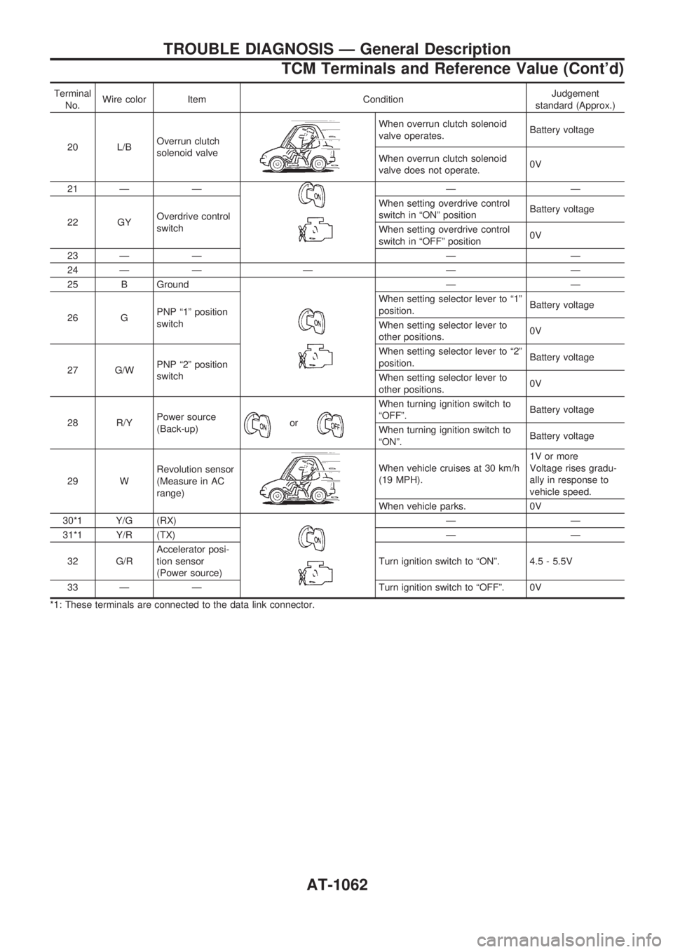
Terminal
No.Wire color Item ConditionJudgement
standard (Approx.)
20 L/BOverrun clutch
solenoid valve
When overrun clutch solenoid
valve operates.Battery voltage
When overrun clutch solenoid
valve does not operate.0V
21 Ð Ð
ÐÐ
22 GYOverdrive control
switchWhen setting overdrive control
switch in ªONº positionBattery voltage
When setting overdrive control
switch in ªOFFº position0V
23 Ð Ð Ð Ð
24 Ð Ð Ð Ð Ð
25 B Ground
ÐÐ
26 GPNP ª1º position
switchWhen setting selector lever to ª1º
position.Battery voltage
When setting selector lever to
other positions.0V
27 G/WPNP ª2º position
switchWhen setting selector lever to ª2º
position.Battery voltage
When setting selector lever to
other positions.0V
28 R/YPower source
(Back-up)
or
When turning ignition switch to
ªOFFº.Battery voltage
When turning ignition switch to
ªONº.Battery voltage
29 WRevolution sensor
(Measure in AC
range)
When vehicle cruises at 30 km/h
(19 MPH).1V or more
Voltage rises gradu-
ally in response to
vehicle speed.
When vehicle parks. 0V
30*1 Y/G (RX)
ÐÐ
31*1 Y/R (TX) Ð Ð
32 G/RAccelerator posi-
tion sensor
(Power source)Turn ignition switch to ªONº. 4.5 - 5.5V
33 Ð Ð Turn ignition switch to ªOFFº. 0V
*1: These terminals are connected to the data link connector.
TROUBLE DIAGNOSIS Ð General Description
TCM Terminals and Reference Value (Cont'd)
AT-1062
Page 107 of 1033
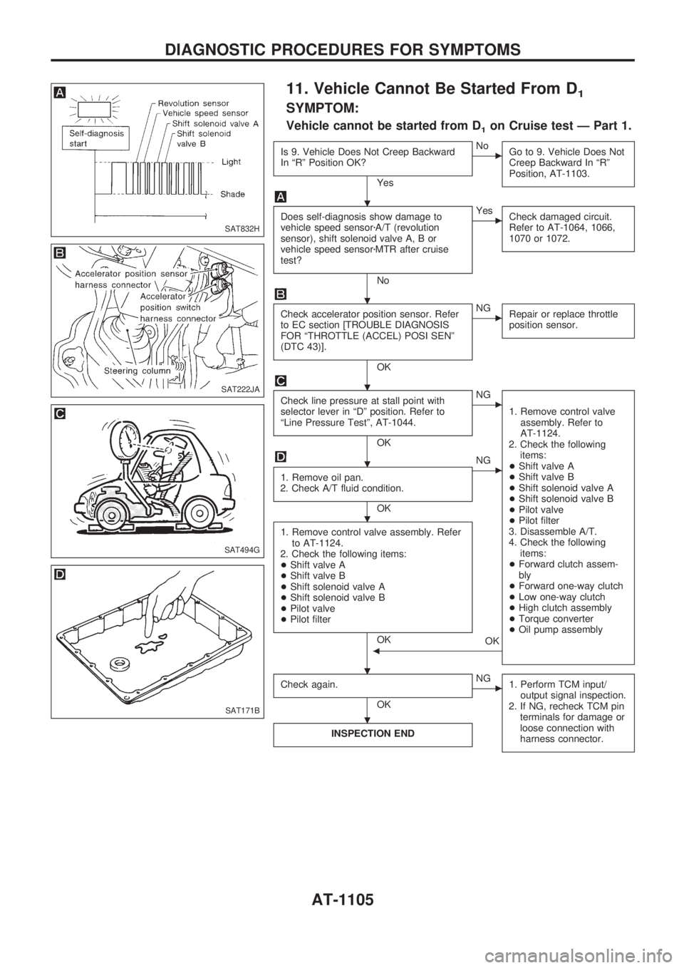
11. Vehicle Cannot Be Started From D1
SYMPTOM:
Vehicle cannot be started from D1on Cruise test Ð Part 1.
Is 9. Vehicle Does Not Creep Backward
In ªRº Position OK?
Yes
cNo
Go to 9. Vehicle Does Not
Creep Backward In ªRº
Position, AT-1103.
Does self-diagnosis show damage to
vehicle speed sensorzA/T (revolution
sensor), shift solenoid valve A, B or
vehicle speed sensorzMTR after cruise
test?
No
cYes
Check damaged circuit.
Refer to AT-1064, 1066,
1070 or 1072.
Check accelerator position sensor. Refer
to EC section [TROUBLE DIAGNOSIS
FOR ªTHROTTLE (ACCEL) POSI SENº
(DTC 43)].
OK
cNG
Repair or replace throttle
position sensor.
Check line pressure at stall point with
selector lever in ªDº position. Refer to
ªLine Pressure Testº, AT-1044.
OK
cNG
1. Remove control valve
assembly. Refer to
AT-1124.
2. Check the following
items:
+Shift valve A
+Shift valve B
+Shift solenoid valve A
+Shift solenoid valve B
+Pilot valve
+Pilot filter
3. Disassemble A/T.
4. Check the following
items:
+Forward clutch assem-
bly
+Forward one-way clutch
+Low one-way clutch
+High clutch assembly
+Torque converter
+Oil pump assembly
1. Remove oil pan.
2. Check A/T fluid condition.
OK
cNG
1. Remove control valve assembly. Refer
to AT-1124.
2. Check the following items:
+Shift valve A
+Shift valve B
+Shift solenoid valve A
+Shift solenoid valve B
+Pilot valve
+Pilot filter
OK
OKb
Check again.
OK
cNG
1. Perform TCM input/
output signal inspection.
2. If NG, recheck TCM pin
terminals for damage or
loose connection with
harness connector.
INSPECTION END
SAT832H
SAT222JA
SAT494G
SAT171B
.
.
.
.
.
. .
.
DIAGNOSTIC PROCEDURES FOR SYMPTOMS
AT-1105
Page 110 of 1033
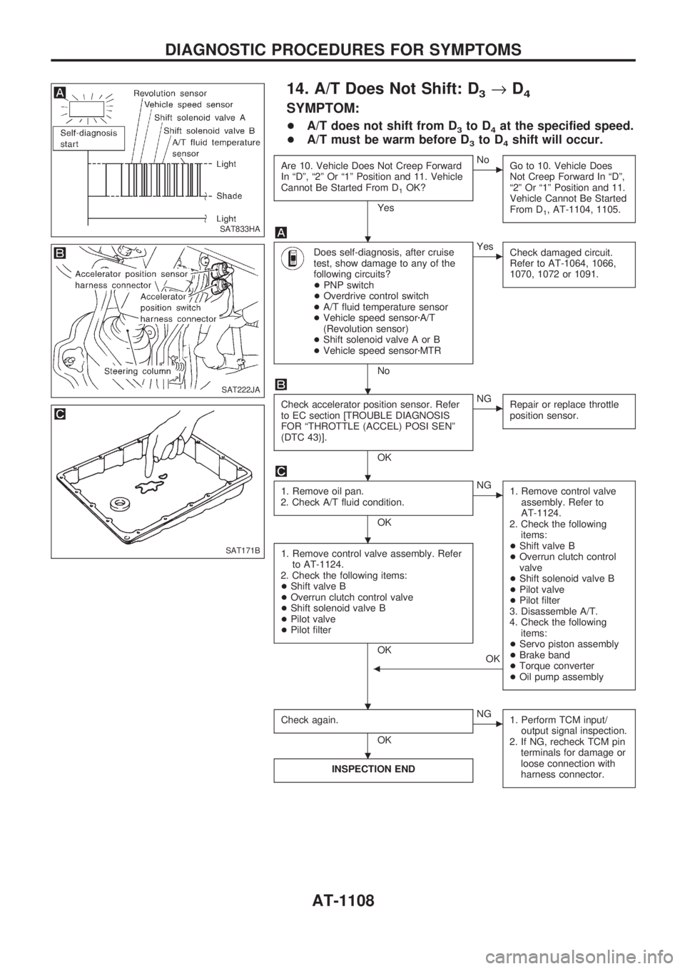
14. A/T Does Not Shift: D3®D4
SYMPTOM:
+A/T does not shift from D3to D4at the specified speed.
+A/T must be warm before D
3to D4shift will occur.
Are 10. Vehicle Does Not Creep Forward
In ªDº, ª2º Or ª1º Position and 11. Vehicle
Cannot Be Started From D
1OK?
Yes
cNo
Go to 10. Vehicle Does
Not Creep Forward In ªDº,
ª2º Or ª1º Position and 11.
Vehicle Cannot Be Started
From D
1, AT-1104, 1105.
Does self-diagnosis, after cruise
test, show damage to any of the
following circuits?
+PNP switch
+Overdrive control switch
+A/T fluid temperature sensor
+Vehicle speed sensorzA/T
(Revolution sensor)
+Shift solenoid valve A or B
+Vehicle speed sensorzMTR
No
cYes
Check damaged circuit.
Refer to AT-1064, 1066,
1070, 1072 or 1091.
Check accelerator position sensor. Refer
to EC section [TROUBLE DIAGNOSIS
FOR ªTHROTTLE (ACCEL) POSI SENº
(DTC 43)].
OK
cNG
Repair or replace throttle
position sensor.
1. Remove oil pan.
2. Check A/T fluid condition.
OK
cNG
1. Remove control valve
assembly. Refer to
AT-1124.
2. Check the following
items:
+Shift valve B
+Overrun clutch control
valve
+Shift solenoid valve B
+Pilot valve
+Pilot filter
3. Disassemble A/T.
4. Check the following
items:
+Servo piston assembly
+Brake band
+Torque converter
+Oil pump assembly
1. Remove control valve assembly. Refer
to AT-1124.
2. Check the following items:
+Shift valve B
+Overrun clutch control valve
+Shift solenoid valve B
+Pilot valve
+Pilot filter
OK
OK
b
Check again.
OK
cNG
1. Perform TCM input/
output signal inspection.
2. If NG, recheck TCM pin
terminals for damage or
loose connection with
harness connector.
INSPECTION END
SAT833HA
SAT222JA
SAT171B
.
.
.
.
. .
.
DIAGNOSTIC PROCEDURES FOR SYMPTOMS
AT-1108