2000 NISSAN PATROL tow
[x] Cancel search: towPage 6 of 1033
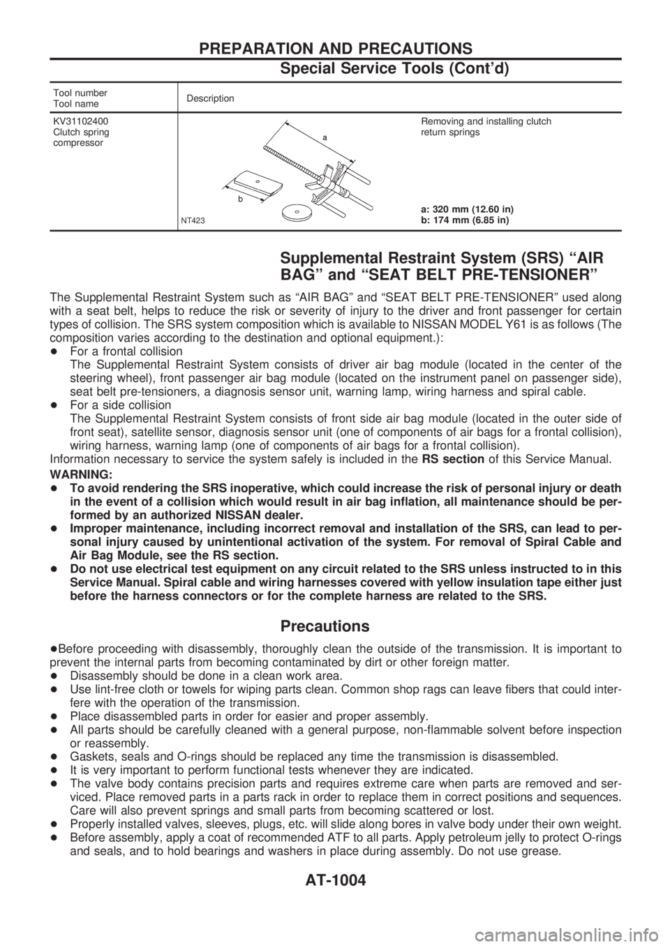
Tool number
Tool nameDescription
KV31102400
Clutch spring
compressor
NT423
Removing and installing clutch
return springs
a: 320 mm (12.60 in)
b: 174 mm (6.85 in)
Supplemental Restraint System (SRS) ªAIR
BAGº and ªSEAT BELT PRE-TENSIONERº
The Supplemental Restraint System such as ªAIR BAGº and ªSEAT BELT PRE-TENSIONERº used along
with a seat belt, helps to reduce the risk or severity of injury to the driver and front passenger for certain
types of collision. The SRS system composition which is available to NISSAN MODEL Y61 is as follows (The
composition varies according to the destination and optional equipment.):
+For a frontal collision
The Supplemental Restraint System consists of driver air bag module (located in the center of the
steering wheel), front passenger air bag module (located on the instrument panel on passenger side),
seat belt pre-tensioners, a diagnosis sensor unit, warning lamp, wiring harness and spiral cable.
+For a side collision
The Supplemental Restraint System consists of front side air bag module (located in the outer side of
front seat), satellite sensor, diagnosis sensor unit (one of components of air bags for a frontal collision),
wiring harness, warning lamp (one of components of air bags for a frontal collision).
Information necessary to service the system safely is included in theRS sectionof this Service Manual.
WARNING:
+To avoid rendering the SRS inoperative, which could increase the risk of personal injury or death
in the event of a collision which would result in air bag inflation, all maintenance should be per-
formed by an authorized NISSAN dealer.
+Improper maintenance, including incorrect removal and installation of the SRS, can lead to per-
sonal injury caused by unintentional activation of the system. For removal of Spiral Cable and
Air Bag Module, see the RS section.
+Do not use electrical test equipment on any circuit related to the SRS unless instructed to in this
Service Manual. Spiral cable and wiring harnesses covered with yellow insulation tape either just
before the harness connectors or for the complete harness are related to the SRS.
Precautions
+Before proceeding with disassembly, thoroughly clean the outside of the transmission. It is important to
prevent the internal parts from becoming contaminated by dirt or other foreign matter.
+Disassembly should be done in a clean work area.
+Use lint-free cloth or towels for wiping parts clean. Common shop rags can leave fibers that could inter-
fere with the operation of the transmission.
+Place disassembled parts in order for easier and proper assembly.
+All parts should be carefully cleaned with a general purpose, non-flammable solvent before inspection
or reassembly.
+Gaskets, seals and O-rings should be replaced any time the transmission is disassembled.
+It is very important to perform functional tests whenever they are indicated.
+The valve body contains precision parts and requires extreme care when parts are removed and ser-
viced. Place removed parts in a parts rack in order to replace them in correct positions and sequences.
Care will also prevent springs and small parts from becoming scattered or lost.
+Properly installed valves, sleeves, plugs, etc. will slide along bores in valve body under their own weight.
+Before assembly, apply a coat of recommended ATF to all parts. Apply petroleum jelly to protect O-rings
and seals, and to hold bearings and washers in place during assembly. Do not use grease.
PREPARATION AND PRECAUTIONS
Special Service Tools (Cont'd)
AT-1004
Page 148 of 1033
Side clearances
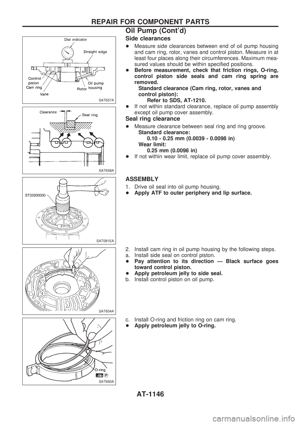
+Measure side clearances between end of oil pump housing
and cam ring, rotor, vanes and control piston. Measure in at
least four places along their circumferences. Maximum mea-
sured values should be within specified positions.
+Before measurement, check that friction rings, O-ring,
control piston side seals and cam ring spring are
removed.
Standard clearance (Cam ring, rotor, vanes and
control piston):
Refer to SDS, AT-1210.
+If not within standard clearance, replace oil pump assembly
except oil pump cover assembly.
Seal ring clearance
+Measure clearance between seal ring and ring groove.
Standard clearance:
0.10 - 0.25 mm (0.0039 - 0.0098 in)
Wear limit:
0.25 mm (0.0098 in)
+If not within wear limit, replace oil pump cover assembly.
ASSEMBLY
1. Drive oil seal into oil pump housing.
+Apply ATF to outer periphery and lip surface.
2. Install cam ring in oil pump housing by the following steps.
a. Install side seal on control piston.
+Pay attention to its direction Ð Black surface goes
toward control piston.
+Apply petroleum jelly to side seal.
b. Install control piston on oil pump.
c. Install O-ring and friction ring on cam ring.
+Apply petroleum jelly to O-ring.
SAT657A
SAT658A
SAT081EA
SAT654A
SAT660A
REPAIR FOR COMPONENT PARTS
Oil Pump (Cont'd)
AT-1146
Page 262 of 1033
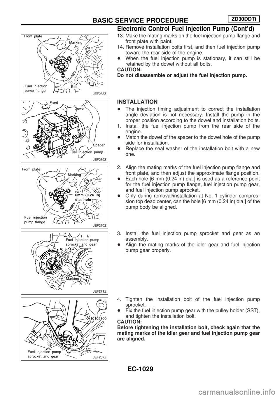
13. Make the mating marks on the fuel injection pump flange and
front plate with paint.
14. Remove installation bolts first, and then fuel injection pump
toward the rear side of the engine.
+When the fuel injection pump is stationary, it can still be
retained by the dowel without all bolts.
CAUTION:
Do not disassemble or adjust the fuel injection pump.
INSTALLATION
+The injection timing adjustment to correct the installation
angle deviation is not necessary. Install the pump in the
proper position according to the dowel and installation bolts.
1. Install the fuel injection pump from the rear side of the
engine.
+Match the dowel of the spacer to the dowel hole of the pump
side for installation.
+Replace the seal washer of the installation bolt with a new
one.
2. Align the mating marks of the fuel injection pump flange and
front plate, and then adjust the approximate flange position.
+Each hole [6 mm (0.24 in) dia.] is used as a reference point
for the fuel injection pump flange, fuel injection pump gear,
and fuel injection pump sprocket.
+Only during removal/installation at No. 1 cylinder compres-
sion top dead center, can the hole [6 mm (0.24 in) dia.] of the
pump body be aligned.
3. Install the fuel injection pump sprocket and gear as an
assembly.
+Align the mating marks of the idler gear and fuel injection
pump gear properly.
4. Tighten the installation bolt of the fuel injection pump
sprocket.
+Fix the fuel injection pump gear with the pulley holder (SST),
and tighten the installation bolt.
CAUTION:
Before tightening the installation bolt, check again that the
mating marks of the idler gear and fuel injection pump gear
are aligned.
JEF268Z
JEF269Z
JEF270Z
JEF271Z
JEF267Z
BASIC SERVICE PROCEDUREZD30DDTi
Electronic Control Fuel Injection Pump (Cont'd)
EC-1029
Page 789 of 1033
VALVE OIL SEAL
1. Remove timing chain. Refer to EM-1027, ªTIMING CHAINº.
2. Remove injection nozzle assembly. Refer to ªInjection Tube
and Injection Nozzleº in ªBASIC SERVICE PROCEDUREº in
EC section.
3. Remove camshaft. Refer to EM-1031, ªCAMSHAFTº.
4. Remove valve lifters and mark order No. on each lifter.
5. Replace valve oil seal according to the following procedure.
When replacing valve oil seal, set the corresponding piston
at TDC. Failure to do so causes the valve to drop into the
cylinder.
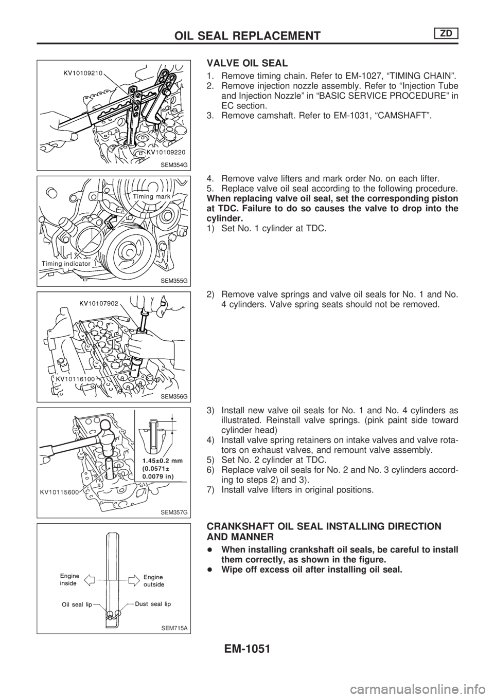
1) Set No. 1 cylinder at TDC.
2) Remove valve springs and valve oil seals for No. 1 and No.
4 cylinders. Valve spring seats should not be removed.
3) Install new valve oil seals for No. 1 and No. 4 cylinders as
illustrated. Reinstall valve springs. (pink paint side toward
cylinder head)
4) Install valve spring retainers on intake valves and valve rota-
tors on exhaust valves, and remount valve assembly.
5) Set No. 2 cylinder at TDC.
6) Replace valve oil seals for No. 2 and No. 3 cylinders accord-
ing to steps 2) and 3).
7) Install valve lifters in original positions.
CRANKSHAFT OIL SEAL INSTALLING DIRECTION
AND MANNER
+When installing crankshaft oil seals, be careful to install
them correctly, as shown in the figure.
+Wipe off excess oil after installing oil seal.
SEM354G
SEM355G
SEM356G
SEM357G
SEM715A
OIL SEAL REPLACEMENTZD
EM-1051
Page 793 of 1033
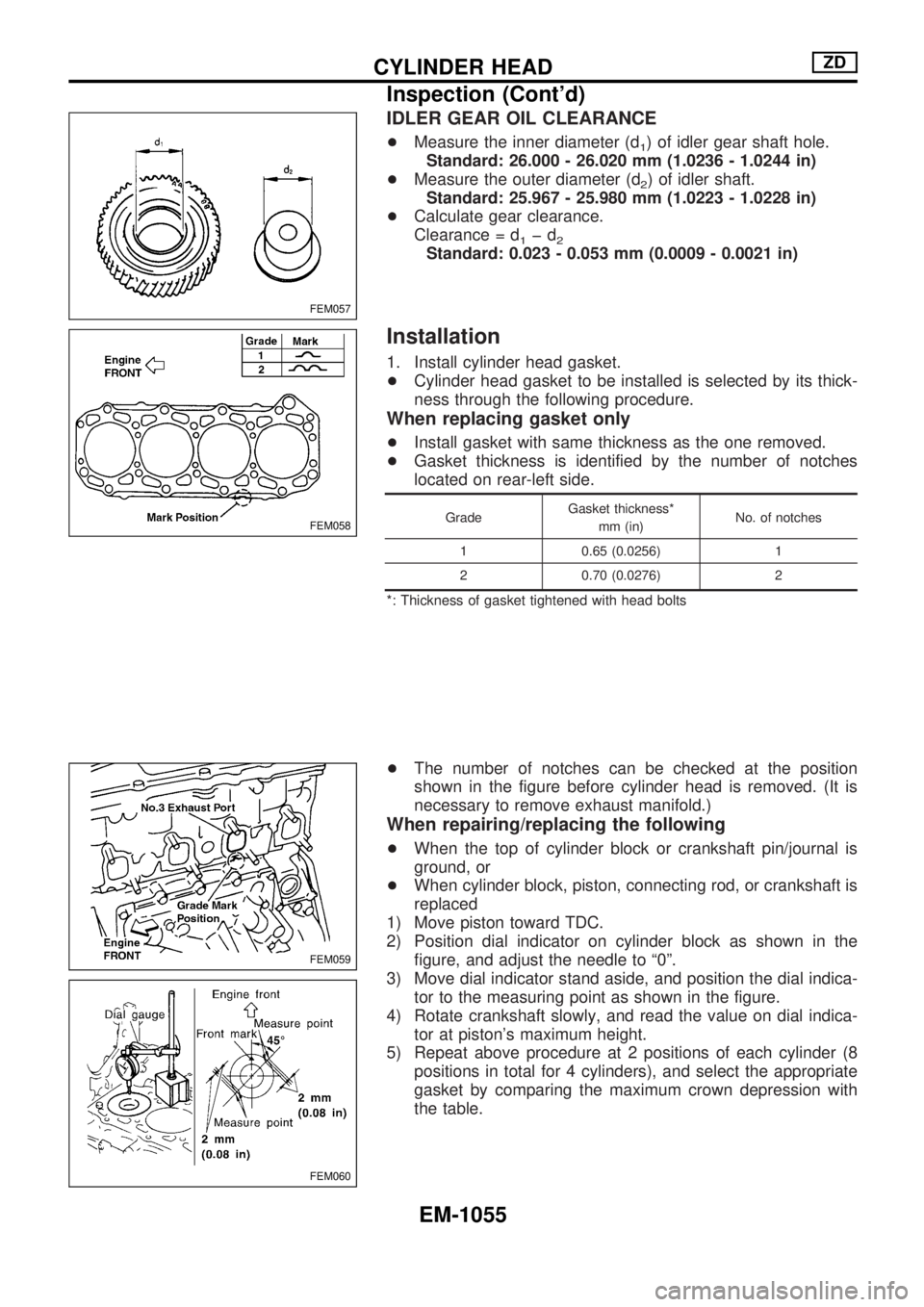
IDLER GEAR OIL CLEARANCE
+Measure the inner diameter (d1) of idler gear shaft hole.
Standard: 26.000 - 26.020 mm (1.0236 - 1.0244 in)
+Measure the outer diameter (d
2) of idler shaft.
Standard: 25.967 - 25.980 mm (1.0223 - 1.0228 in)
+Calculate gear clearance.
Clearance = d
1þd2Standard: 0.023 - 0.053 mm (0.0009 - 0.0021 in)
Installation
1. Install cylinder head gasket.
+Cylinder head gasket to be installed is selected by its thick-
ness through the following procedure.
When replacing gasket only
+Install gasket with same thickness as the one removed.
+Gasket thickness is identified by the number of notches
located on rear-left side.
GradeGasket thickness*
mm (in)No. of notches
1 0.65 (0.0256) 1
2 0.70 (0.0276) 2
*: Thickness of gasket tightened with head bolts
+The number of notches can be checked at the position
shown in the figure before cylinder head is removed. (It is
necessary to remove exhaust manifold.)
When repairing/replacing the following
+When the top of cylinder block or crankshaft pin/journal is
ground, or
+When cylinder block, piston, connecting rod, or crankshaft is
replaced
1) Move piston toward TDC.
2) Position dial indicator on cylinder block as shown in the
figure, and adjust the needle to ª0º.
3) Move dial indicator stand aside, and position the dial indica-
tor to the measuring point as shown in the figure.
4) Rotate crankshaft slowly, and read the value on dial indica-
tor at piston's maximum height.
5) Repeat above procedure at 2 positions of each cylinder (8
positions in total for 4 cylinders), and select the appropriate
gasket by comparing the maximum crown depression with
the table.
FEM057
FEM058
FEM059
FEM060
CYLINDER HEADZD
Inspection (Cont'd)
EM-1055
Page 796 of 1033
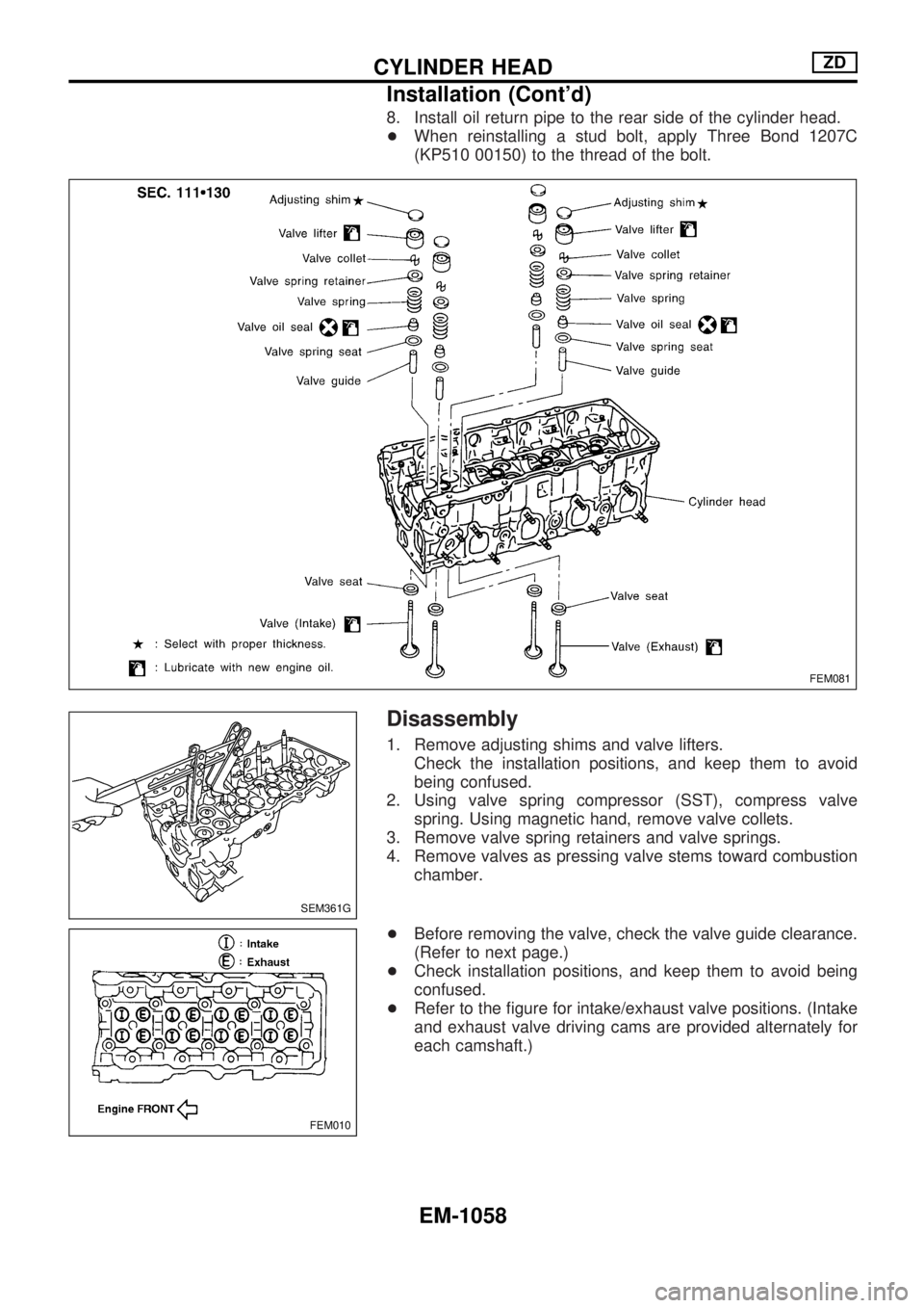
8. Install oil return pipe to the rear side of the cylinder head.
+When reinstalling a stud bolt, apply Three Bond 1207C
(KP510 00150) to the thread of the bolt.
Disassembly
1. Remove adjusting shims and valve lifters.
Check the installation positions, and keep them to avoid
being confused.
2. Using valve spring compressor (SST), compress valve
spring. Using magnetic hand, remove valve collets.
3. Remove valve spring retainers and valve springs.
4. Remove valves as pressing valve stems toward combustion
chamber.
+Before removing the valve, check the valve guide clearance.
(Refer to next page.)
+Check installation positions, and keep them to avoid being
confused.
+Refer to the figure for intake/exhaust valve positions. (Intake
and exhaust valve driving cams are provided alternately for
each camshaft.)
FEM081
SEM361G
FEM010
CYLINDER HEADZD
Installation (Cont'd)
EM-1058
Page 797 of 1033
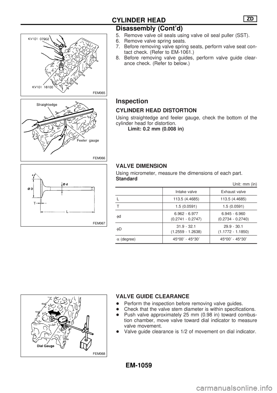
5. Remove valve oil seals using valve oil seal puller (SST).
6. Remove valve spring seats.
7. Before removing valve spring seats, perform valve seat con-
tact check. (Refer to EM-1061.)
8. Before removing valve guides, perform valve guide clear-
ance check. (Refer to below.)
Inspection
CYLINDER HEAD DISTORTION
Using straightedge and feeler gauge, check the bottom of the
cylinder head for distortion.
Limit: 0.2 mm (0.008 in)
VALVE DIMENSION
Using micrometer, measure the dimensions of each part.
Standard
Unit: mm (in)
Intake valve Exhaust valve
L 113.5 (4.4685) 113.5 (4.4685)
T 1.5 (0.0591) 1.5 (0.0591)
fd6.962 - 6.977
(0.2741 - 0.2747)6.945 - 6.960
(0.2734 - 0.2740)
fD31.9 - 32.1
(1.2559 - 1.2638)29.9 - 30.1
(1.1772 - 1.1850)
a(degree) 45É00¢- 45É30¢45É00¢- 45É30¢
VALVE GUIDE CLEARANCE
+Perform the inspection before removing valve guides.
+Check that the valve stem diameter is within specifications.
+Push valve approximately 25 mm (0.98 in) toward combus-
tion chamber, move valve toward dial indicator to measure
valve movement.
+Valve guide clearance is 1/2 of movement on dial indicator.
FEM065
FEM066
FEM067
FEM068
CYLINDER HEADZD
Disassembly (Cont'd)
EM-1059
Page 820 of 1033
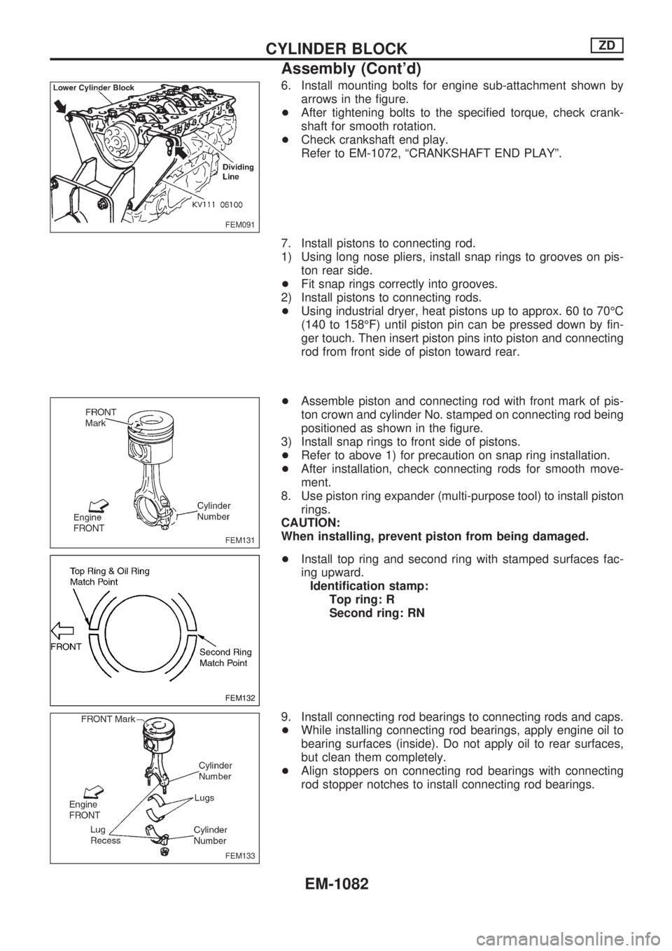
6. Install mounting bolts for engine sub-attachment shown by
arrows in the figure.
+After tightening bolts to the specified torque, check crank-
shaft for smooth rotation.
+Check crankshaft end play.
Refer to EM-1072, ªCRANKSHAFT END PLAYº.
7. Install pistons to connecting rod.
1) Using long nose pliers, install snap rings to grooves on pis-
ton rear side.
+Fit snap rings correctly into grooves.
2) Install pistons to connecting rods.
+Using industrial dryer, heat pistons up to approx. 60 to 70ÉC
(140 to 158ÉF) until piston pin can be pressed down by fin-
ger touch. Then insert piston pins into piston and connecting
rod from front side of piston toward rear.
+Assemble piston and connecting rod with front mark of pis-
ton crown and cylinder No. stamped on connecting rod being
positioned as shown in the figure.
3) Install snap rings to front side of pistons.
+Refer to above 1) for precaution on snap ring installation.
+After installation, check connecting rods for smooth move-
ment.
8. Use piston ring expander (multi-purpose tool) to install piston
rings.
CAUTION:
When installing, prevent piston from being damaged.
+Install top ring and second ring with stamped surfaces fac-
ing upward.
Identification stamp:
Top ring: R
Second ring: RN
9. Install connecting rod bearings to connecting rods and caps.
+While installing connecting rod bearings, apply engine oil to
bearing surfaces (inside). Do not apply oil to rear surfaces,
but clean them completely.
+Align stoppers on connecting rod bearings with connecting
rod stopper notches to install connecting rod bearings.
FEM091
FEM131
FEM132
FEM133
CYLINDER BLOCKZD
Assembly (Cont'd)
EM-1082