2000 NISSAN PATROL ECO mode
[x] Cancel search: ECO modePage 2 of 1033

FOREWORD
This manual contains maintenance and repair procedures for NISSAN
PATROL GR,modelY61 series.
In order to assure your safety and the efficient functioning of the vehicle,
this manual should be read thoroughly. It is especially important that the
PRECAUTIONS in the GI section be completely understood before starting
any repair task.
All information in this manual is based on the latest product information
at the time of publication. The right is reserved to make changes in speci-
®cations and methods at any time without notice.
IMPORTANT SAFETY NOTICE
The proper performance of service is essential for both the safety of the
technician and the efficient functioning of the vehicle.
The service methods in this Service Manual are described in such a man-
ner that the service may be performed safely and accurately.
Service varies with the procedures used, the skills of the technician and the
tools and parts available. Accordingly, anyone using service procedures,
tools or parts which are not speci®cally recommended by NISSAN must
®rst completely satisfy himself that neither his safety nor the vehicle's
safety will be jeopardized by the service method selected.
NISSAN EUROPE S.A.S.
Service Engineering SectionParis, France
Page 6 of 1033
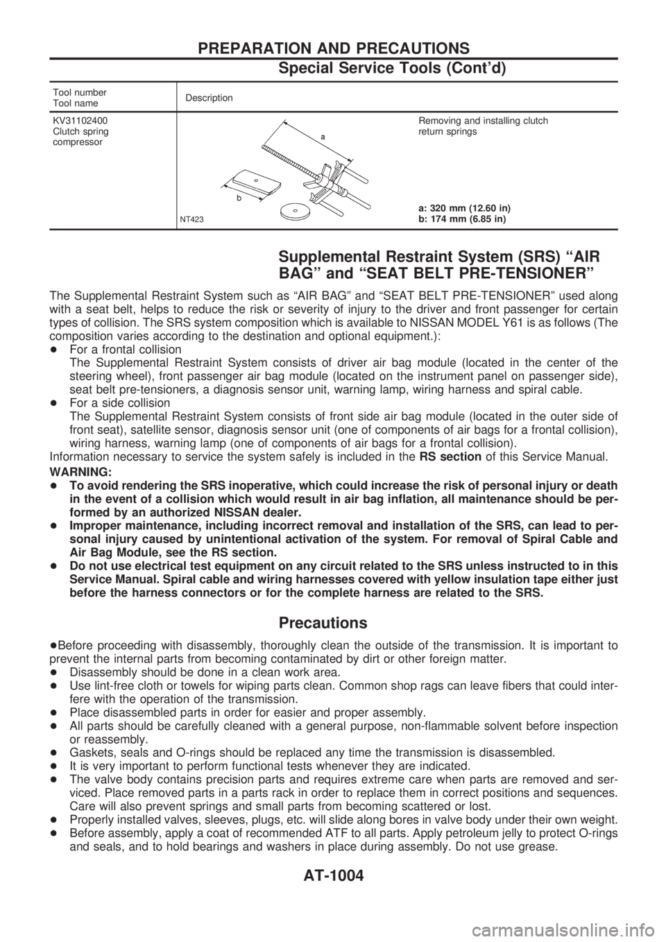
Tool number
Tool nameDescription
KV31102400
Clutch spring
compressor
NT423
Removing and installing clutch
return springs
a: 320 mm (12.60 in)
b: 174 mm (6.85 in)
Supplemental Restraint System (SRS) ªAIR
BAGº and ªSEAT BELT PRE-TENSIONERº
The Supplemental Restraint System such as ªAIR BAGº and ªSEAT BELT PRE-TENSIONERº used along
with a seat belt, helps to reduce the risk or severity of injury to the driver and front passenger for certain
types of collision. The SRS system composition which is available to NISSAN MODEL Y61 is as follows (The
composition varies according to the destination and optional equipment.):
+For a frontal collision
The Supplemental Restraint System consists of driver air bag module (located in the center of the
steering wheel), front passenger air bag module (located on the instrument panel on passenger side),
seat belt pre-tensioners, a diagnosis sensor unit, warning lamp, wiring harness and spiral cable.
+For a side collision
The Supplemental Restraint System consists of front side air bag module (located in the outer side of
front seat), satellite sensor, diagnosis sensor unit (one of components of air bags for a frontal collision),
wiring harness, warning lamp (one of components of air bags for a frontal collision).
Information necessary to service the system safely is included in theRS sectionof this Service Manual.
WARNING:
+To avoid rendering the SRS inoperative, which could increase the risk of personal injury or death
in the event of a collision which would result in air bag inflation, all maintenance should be per-
formed by an authorized NISSAN dealer.
+Improper maintenance, including incorrect removal and installation of the SRS, can lead to per-
sonal injury caused by unintentional activation of the system. For removal of Spiral Cable and
Air Bag Module, see the RS section.
+Do not use electrical test equipment on any circuit related to the SRS unless instructed to in this
Service Manual. Spiral cable and wiring harnesses covered with yellow insulation tape either just
before the harness connectors or for the complete harness are related to the SRS.
Precautions
+Before proceeding with disassembly, thoroughly clean the outside of the transmission. It is important to
prevent the internal parts from becoming contaminated by dirt or other foreign matter.
+Disassembly should be done in a clean work area.
+Use lint-free cloth or towels for wiping parts clean. Common shop rags can leave fibers that could inter-
fere with the operation of the transmission.
+Place disassembled parts in order for easier and proper assembly.
+All parts should be carefully cleaned with a general purpose, non-flammable solvent before inspection
or reassembly.
+Gaskets, seals and O-rings should be replaced any time the transmission is disassembled.
+It is very important to perform functional tests whenever they are indicated.
+The valve body contains precision parts and requires extreme care when parts are removed and ser-
viced. Place removed parts in a parts rack in order to replace them in correct positions and sequences.
Care will also prevent springs and small parts from becoming scattered or lost.
+Properly installed valves, sleeves, plugs, etc. will slide along bores in valve body under their own weight.
+Before assembly, apply a coat of recommended ATF to all parts. Apply petroleum jelly to protect O-rings
and seals, and to hold bearings and washers in place during assembly. Do not use grease.
PREPARATION AND PRECAUTIONS
Special Service Tools (Cont'd)
AT-1004
Page 8 of 1033
Service Notice or Precautions
FAIL-SAFE
The TCM has an electronic Fail-Safe (limp home mode). This allows the vehicle to be driven even if a major
electrical input/output device circuit is damaged.
Under Fail-Safe, the vehicle always runs in third gear even with a shift lever position of ª1º, ª2º or ªDº. Cus-
tomer may complain of ªsluggish or poor accelerationº.
When the Fail-Safe operation occurs the next time the key is turned to the ªONº position, the SPORT indi-
cator lamp will blink for about 8 seconds. (For diagnosis, refer to AT-1029.)
The blinking of the SPORT indicator lamp for about 8 seconds will appear only once and be cleared. The
customer may resume normal driving conditions by chance.
Always follow the ªWORK FLOWº (Refer to AT-1040).
The SELF-DIAGNOSIS results will be as follows:
The first SELF-DIAGNOSIS will indicate the damage of the vehicle speed sensor or the revolution
sensor.
During the next SELF-DIAGNOSIS performed after checking the sensor, no damages will be indicated.
PREPARATION AND PRECAUTIONS
AT-1006
Page 29 of 1033
TCM FUNCTION
The function of the TCM is to:
+Receive input signals sent from various switches and sensors.
+Determine required line pressure, shifting point, lock-up operation, and engine brake operation.
+Send required output signals to the respective solenoids.
INPUT/OUTPUT SIGNAL OF TCM
Sensors and solenoid valves Function
InputPNP switch Detects select lever position and sends a signal to TCM.
Accelerator position sensor Detects throttle valve position and sends a signal to TCM.
Accelerator position switch
(Off accel)Detects throttle valve's fully-closed position and sends a signal to TCM.
Accelerator position switch
(Full accel)Detects a throttle valve position of greater than 1/2 of full throttle and sends a
signal to TCM.
Engine speed signal From ECM.
A/T fluid temperature sensor Detects transmission fluid temperature and sends a signal to TCM.
Revolution sensor Detects output shaft rpm and sends a signal to TCM.
Vehicle speed sensorUsed as an auxiliary vehicle speed sensor. Sends a signal when revolution sen-
sor (installed on transmission) malfunctions.
Overdrive control switch
A/T mode switchSends a signal, which prohibits a shift to ªD
4º (overdrive) position, to the TCM.
OutputShift solenoid valve A/BSelects shifting point suited to driving conditions in relation to a signal sent from
TCM.
Line pressure solenoid valveRegulates (or decreases) line pressure suited to driving conditions in relation to
a signal sent from TCM.
Torque converter clutch solenoid valveRegulates (or decreases) lock-up pressure suited to driving conditions in relation
to a signal sent from TCM.
Overrun clutch solenoid valveControls an ªengine brakeº effect suited to driving conditions in relation to a sig-
nal sent from TCM.
O/D OFF indicator lamp
SPORT indicator lampShows TCM faults, when A/T control components malfunction.
OVERALL SYSTEM
Control System (Cont'd)
AT-1027
Page 30 of 1033
Self-diagnosis
After performing this procedure, place check marks for results on
the ªDIAGNOSTIC WORKSHEETº, AT-1038. Reference pages
are provided following the items.
SELF-DIAGNOSTIC PROCEDURE (With
CONSULT-II)
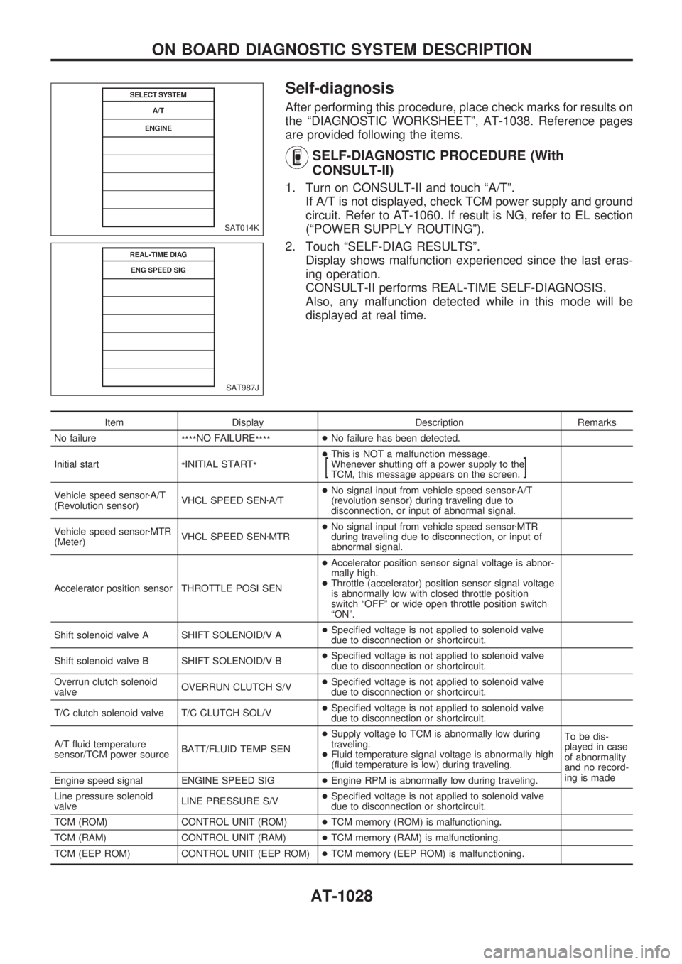
1. Turn on CONSULT-II and touch ªA/Tº.
If A/T is not displayed, check TCM power supply and ground
circuit. Refer to AT-1060. If result is NG, refer to EL section
(ªPOWER SUPPLY ROUTINGº).
2. Touch ªSELF-DIAG RESULTSº.
Display shows malfunction experienced since the last eras-
ing operation.
CONSULT-II performs REAL-TIME SELF-DIAGNOSIS.
Also, any malfunction detected while in this mode will be
displayed at real time.
Item Display Description Remarks
No failure
****NO FAILURE
****+No failure has been detected.
Initial start
*INITIAL START
*+This is NOT a malfunction message.
Whenever shutting off a power supply to the
TCM, this message appears on the screen.
[]
Vehicle speed sensorzA/T
(Revolution sensor)VHCL SPEED SENzA/T+No signal input from vehicle speed sensorzA/T
(revolution sensor) during traveling due to
disconnection, or input of abnormal signal.
Vehicle speed sensorzMTR
(Meter)VHCL SPEED SENzMTR+No signal input from vehicle speed sensorzMTR
during traveling due to disconnection, or input of
abnormal signal.
Accelerator position sensor THROTTLE POSI SEN+Accelerator position sensor signal voltage is abnor-
mally high.
+Throttle (accelerator) position sensor signal voltage
is abnormally low with closed throttle position
switch ªOFFº or wide open throttle position switch
ªONº.
Shift solenoid valve A SHIFT SOLENOID/V A+Specified voltage is not applied to solenoid valve
due to disconnection or shortcircuit.
Shift solenoid valve B SHIFT SOLENOID/V B+Specified voltage is not applied to solenoid valve
due to disconnection or shortcircuit.
Overrun clutch solenoid
valveOVERRUN CLUTCH S/V+Specified voltage is not applied to solenoid valve
due to disconnection or shortcircuit.
T/C clutch solenoid valve T/C CLUTCH SOL/V+Specified voltage is not applied to solenoid valve
due to disconnection or shortcircuit.
A/T fluid temperature
sensor/TCM power sourceBATT/FLUID TEMP SEN+Supply voltage to TCM is abnormally low during
traveling.
+Fluid temperature signal voltage is abnormally high
(fluid temperature is low) during traveling.To be dis-
played in case
of abnormality
and no record-
ing is made
Engine speed signal ENGINE SPEED SIG+Engine RPM is abnormally low during traveling.
Line pressure solenoid
valveLINE PRESSURE S/V+Specified voltage is not applied to solenoid valve
due to disconnection or shortcircuit.
TCM (ROM) CONTROL UNIT (ROM)+TCM memory (ROM) is malfunctioning.
TCM (RAM) CONTROL UNIT (RAM)+TCM memory (RAM) is malfunctioning.
TCM (EEP ROM) CONTROL UNIT (EEP ROM)+TCM memory (EEP ROM) is malfunctioning.
SAT014K
SAT987J
ON BOARD DIAGNOSTIC SYSTEM DESCRIPTION
AT-1028
Page 31 of 1033
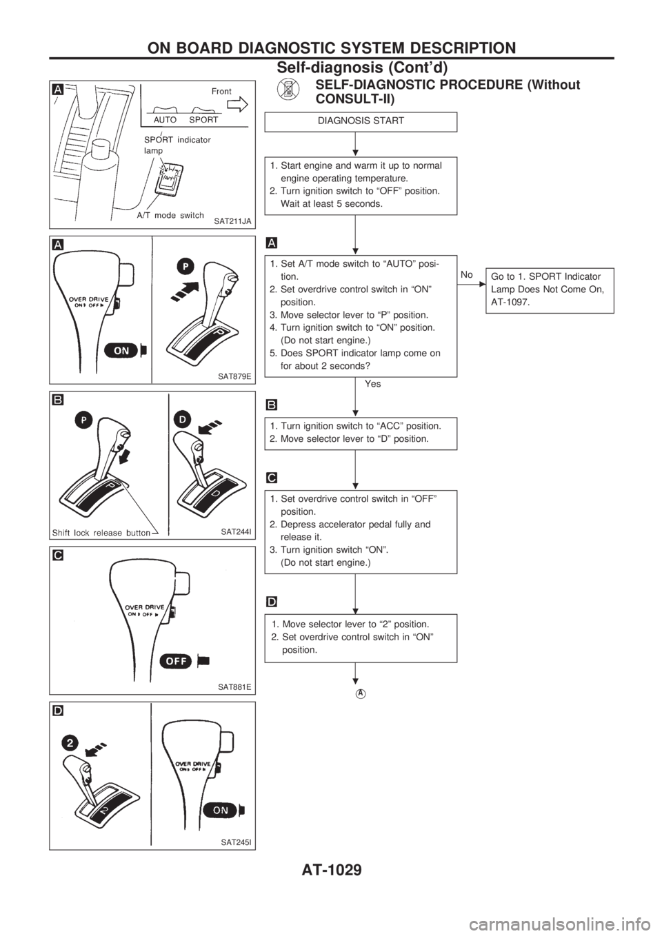
SELF-DIAGNOSTIC PROCEDURE (Without
CONSULT-II)
DIAGNOSIS START
1. Start engine and warm it up to normal
engine operating temperature.
2. Turn ignition switch to ªOFFº position.
Wait at least 5 seconds.
1. Set A/T mode switch to ªAUTOº posi-
tion.
2. Set overdrive control switch in ªONº
position.
3. Move selector lever to ªPº position.
4. Turn ignition switch to ªONº position.
(Do not start engine.)
5. Does SPORT indicator lamp come on
for about 2 seconds?
Yes
cNo
Go to 1. SPORT Indicator
Lamp Does Not Come On,
AT-1097.
1. Turn ignition switch to ªACCº position.
2. Move selector lever to ªDº position.
1. Set overdrive control switch in ªOFFº
position.
2. Depress accelerator pedal fully and
release it.
3. Turn ignition switch ªONº.
(Do not start engine.)
1. Move selector lever to ª2º position.
2. Set overdrive control switch in ªONº
position.
VA
SAT211JA
SAT879E
SAT244I
SAT881E
SAT245I
.
.
.
.
.
.
ON BOARD DIAGNOSTIC SYSTEM DESCRIPTION
Self-diagnosis (Cont'd)
AT-1029
Page 34 of 1033
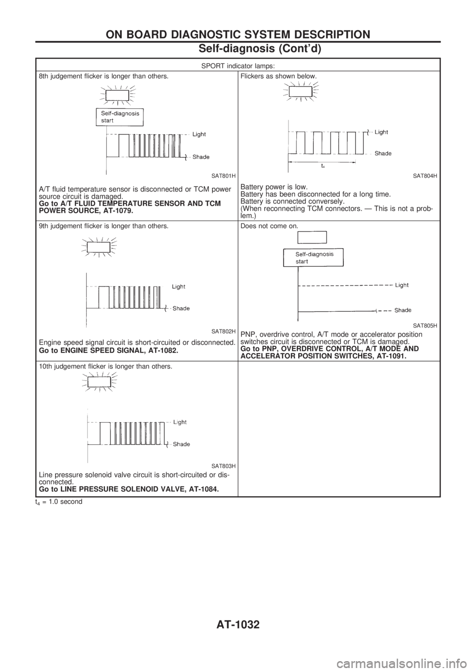
SPORT indicator lamps:
8th judgement flicker is longer than others.
SAT801H
A/T fluid temperature sensor is disconnected or TCM power
source circuit is damaged.
Go to A/T FLUID TEMPERATURE SENSOR AND TCM
POWER SOURCE, AT-1079.
Flickers as shown below.
SAT804H
Battery power is low.
Battery has been disconnected for a long time.
Battery is connected conversely.
(When reconnecting TCM connectors. Ð This is not a prob-
lem.)
9th judgement flicker is longer than others.
SAT802H
Engine speed signal circuit is short-circuited or disconnected.
Go to ENGINE SPEED SIGNAL, AT-1082.
Does not come on.
SAT805H
PNP, overdrive control, A/T mode or accelerator position
switches circuit is disconnected or TCM is damaged.
Go to PNP, OVERDRIVE CONTROL, A/T MODE AND
ACCELERATOR POSITION SWITCHES, AT-1091.
10th judgement flicker is longer than others.
SAT803H
Line pressure solenoid valve circuit is short-circuited or dis-
connected.
Go to LINE PRESSURE SOLENOID VALVE, AT-1084.
t4= 1.0 second
ON BOARD DIAGNOSTIC SYSTEM DESCRIPTION
Self-diagnosis (Cont'd)
AT-1032
Page 39 of 1033
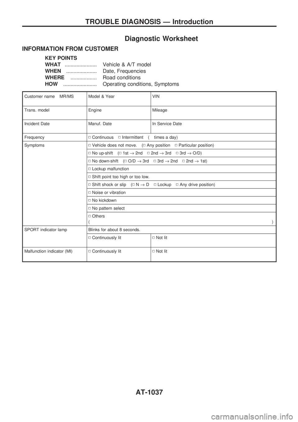
Diagnostic Worksheet
INFORMATION FROM CUSTOMER
KEY POINTS
WHAT...................... Vehicle & A/T model
WHEN..................... Date, Frequencies
WHERE.................. Road conditions
HOW....................... Operating conditions, Symptoms
Customer name MR/MS Model & Year VIN
Trans. model Engine Mileage
Incident Date Manuf. Date In Service Date
FrequencyNContinuousNIntermittent ( times a day)
SymptomsNVehicle does not move. (NAny positionNParticular position)
NNo up-shift (N1st®2ndN2nd®3rdN3rd®O/D)
NNo down-shift (NO/D®3rdN3rd®2ndN2nd®1st)
NLockup malfunction
NShift point too high or too low.
NShift shock or slip (NN®DNLockupNAny drive position)
NNoise or vibration
NNo kickdown
NNo pattern select
NOthers
()
SPORT indicator lamp Blinks for about 8 seconds.
NContinuously litNNot lit
Malfunction indicator (MI)NContinuously litNNot lit
TROUBLE DIAGNOSIS Ð Introduction
AT-1037