2000 NISSAN PATROL gauge
[x] Cancel search: gaugePage 5 of 1033
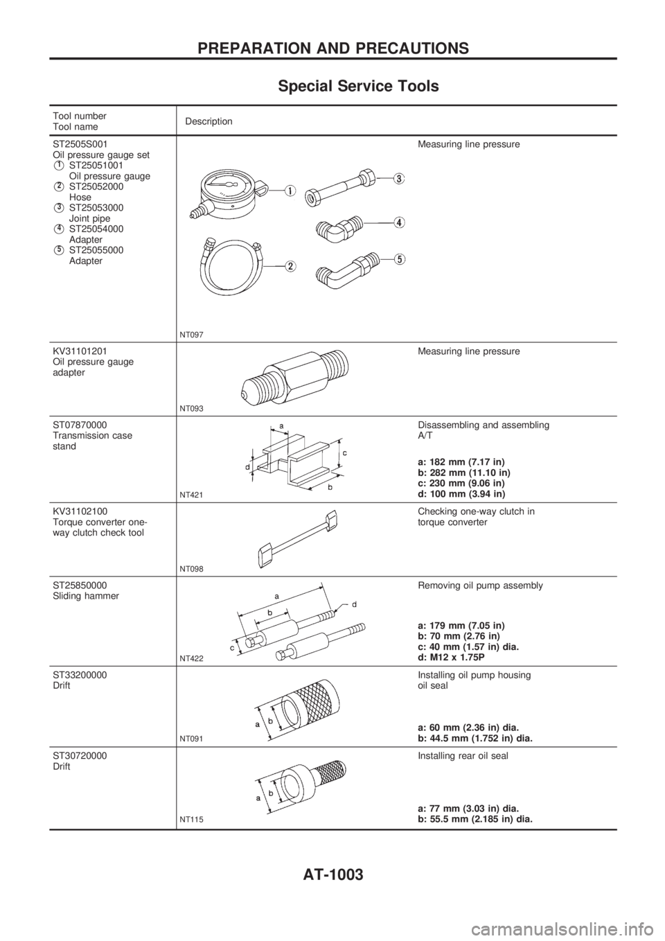
Special Service Tools
Tool number
Tool nameDescription
ST2505S001
Oil pressure gauge set
V1ST25051001
Oil pressure gauge
V2ST25052000
Hose
V3ST25053000
Joint pipe
V4ST25054000
Adapter
V5ST25055000
Adapter
NT097
Measuring line pressure
KV31101201
Oil pressure gauge
adapter
NT093
Measuring line pressure
ST07870000
Transmission case
stand
NT421
Disassembling and assembling
A/T
a: 182 mm (7.17 in)
b: 282 mm (11.10 in)
c: 230 mm (9.06 in)
d: 100 mm (3.94 in)
KV31102100
Torque converter one-
way clutch check tool
NT098
Checking one-way clutch in
torque converter
ST25850000
Sliding hammer
NT422
Removing oil pump assembly
a: 179 mm (7.05 in)
b: 70 mm (2.76 in)
c: 40 mm (1.57 in) dia.
d: M12 x 1.75P
ST33200000
Drift
NT091
Installing oil pump housing
oil seal
a: 60 mm (2.36 in) dia.
b: 44.5 mm (1.752 in) dia.
ST30720000
Drift
NT115
Installing rear oil seal
a: 77 mm (3.03 in) dia.
b: 55.5 mm (2.185 in) dia.
PREPARATION AND PRECAUTIONS
AT-1003
Page 46 of 1033
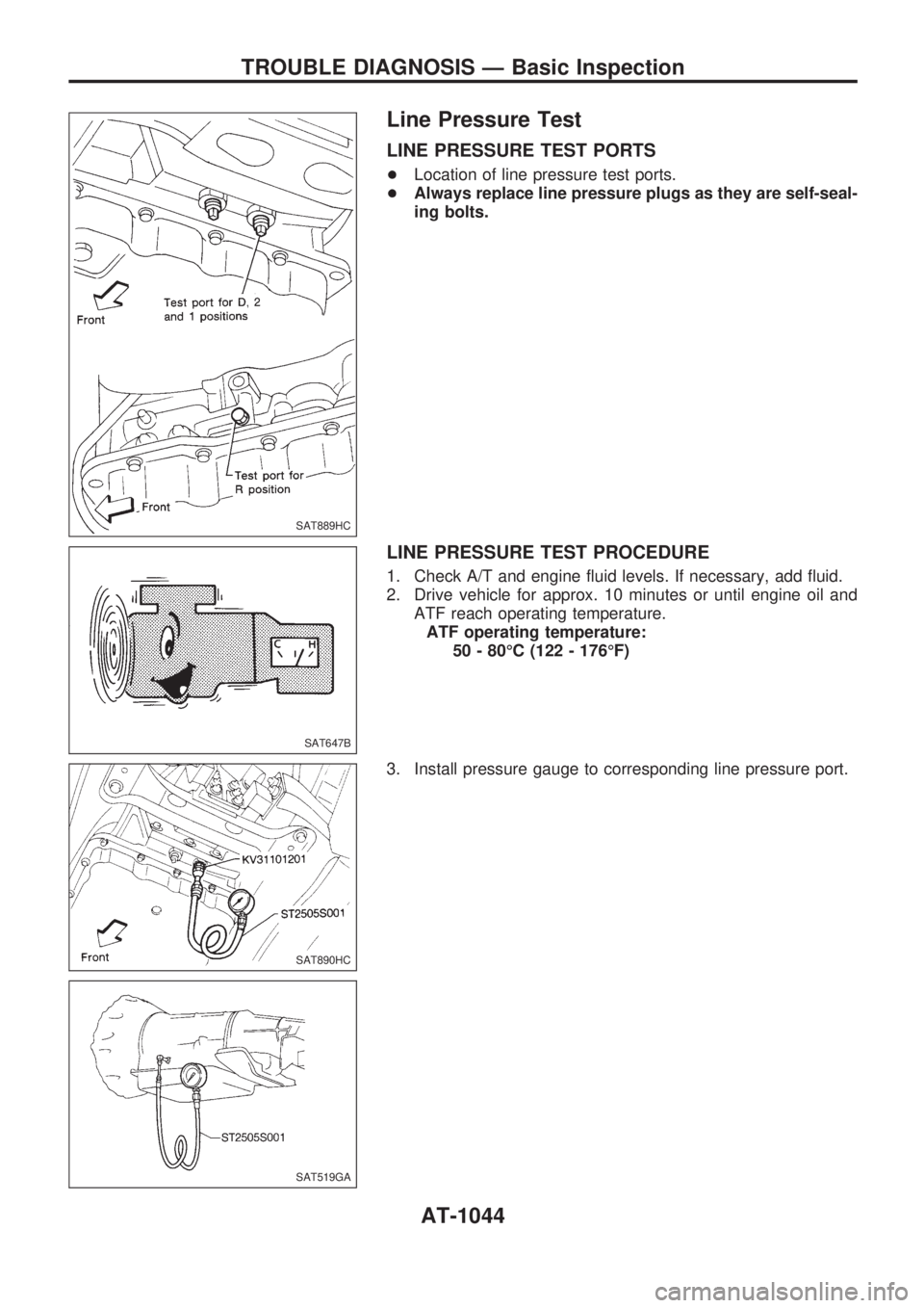
Line Pressure Test
LINE PRESSURE TEST PORTS
+Location of line pressure test ports.
+Always replace line pressure plugs as they are self-seal-
ing bolts.
LINE PRESSURE TEST PROCEDURE
1. Check A/T and engine fluid levels. If necessary, add fluid.
2. Drive vehicle for approx. 10 minutes or until engine oil and
ATF reach operating temperature.
ATF operating temperature:
50 - 80ÉC (122 - 176ÉF)
3. Install pressure gauge to corresponding line pressure port.
SAT889HC
SAT647B
SAT890HC
SAT519GA
TROUBLE DIAGNOSIS Ð Basic Inspection
AT-1044
Page 69 of 1033
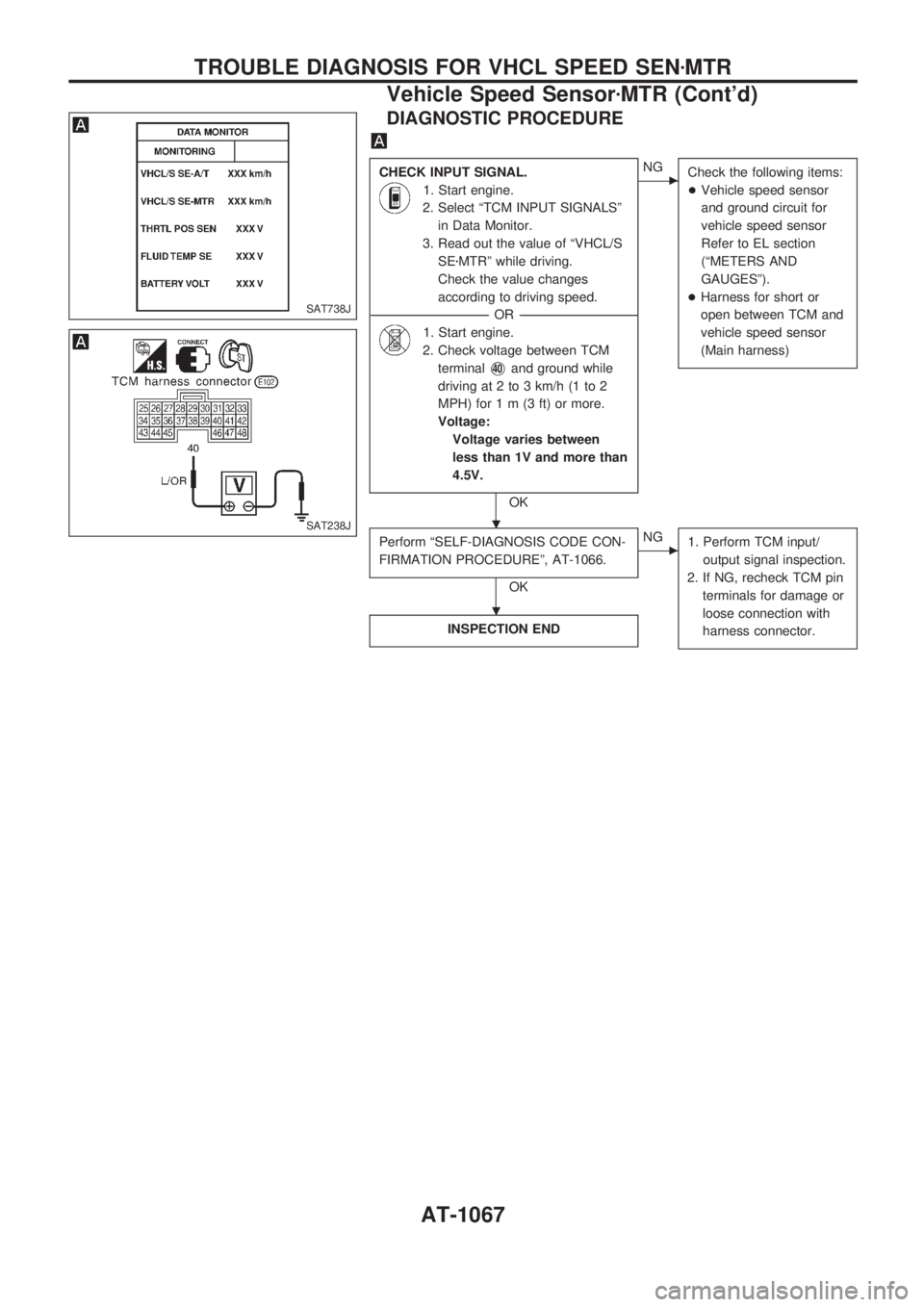
DIAGNOSTIC PROCEDURE
CHECK INPUT SIGNAL.
1. Start engine.
2. Select ªTCM INPUT SIGNALSº
in Data Monitor.
3. Read out the value of ªVHCL/S
SEzMTRº while driving.
Check the value changes
according to driving speed.
------------------------------------------------------------------------------------------------------------------------------------OR------------------------------------------------------------------------------------------------------------------------------------
1. Start engine.
2. Check voltage between TCM
terminal
V40and ground while
driving at 2 to 3 km/h (1 to 2
MPH) for1m(3ft)ormore.
Voltage:
Voltage varies between
less than 1V and more than
4.5V.
OK
cNG
Check the following items:
+Vehicle speed sensor
and ground circuit for
vehicle speed sensor
Refer to EL section
(ªMETERS AND
GAUGESº).
+Harness for short or
open between TCM and
vehicle speed sensor
(Main harness)
Perform ªSELF-DIAGNOSIS CODE CON-
FIRMATION PROCEDUREº, AT-1066.
OK
cNG
1. Perform TCM input/
output signal inspection.
2. If NG, recheck TCM pin
terminals for damage or
loose connection with
harness connector.
INSPECTION END
SAT738J
SAT238J.
.
TROUBLE DIAGNOSIS FOR VHCL SPEED SENzMTR
Vehicle Speed SensorzMTR (Cont'd)
AT-1067
Page 258 of 1033
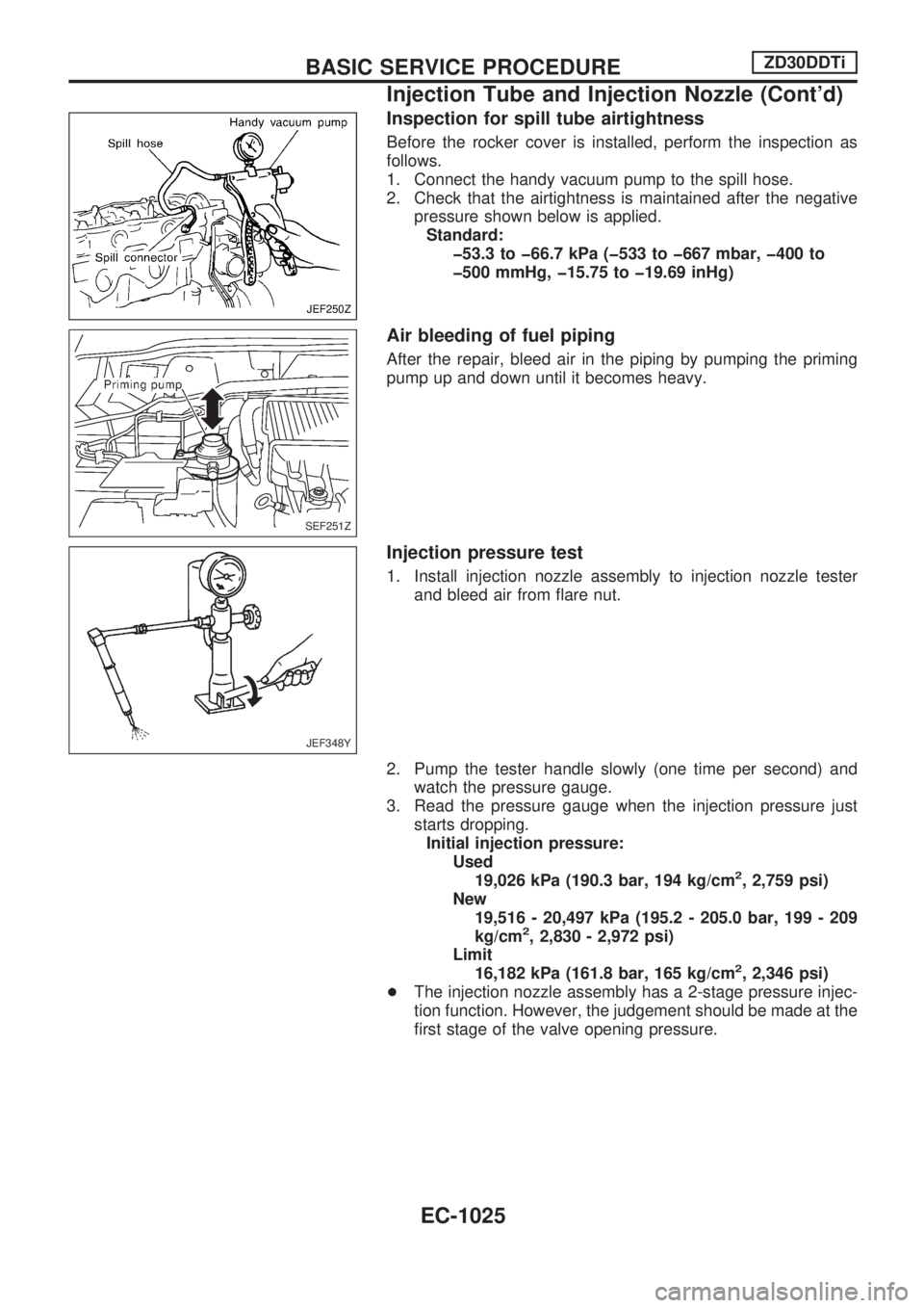
Inspection for spill tube airtightness
Before the rocker cover is installed, perform the inspection as
follows.
1. Connect the handy vacuum pump to the spill hose.
2. Check that the airtightness is maintained after the negative
pressure shown below is applied.
Standard:
þ53.3 to þ66.7 kPa (þ533 to þ667 mbar, þ400 to
þ500 mmHg, þ15.75 to þ19.69 inHg)
Air bleeding of fuel piping
After the repair, bleed air in the piping by pumping the priming
pump up and down until it becomes heavy.
Injection pressure test
1. Install injection nozzle assembly to injection nozzle tester
and bleed air from flare nut.
2. Pump the tester handle slowly (one time per second) and
watch the pressure gauge.
3. Read the pressure gauge when the injection pressure just
starts dropping.
Initial injection pressure:
Used
19,026 kPa (190.3 bar, 194 kg/cm
2, 2,759 psi)
New
19,516 - 20,497 kPa (195.2 - 205.0 bar, 199 - 209
kg/cm
2, 2,830 - 2,972 psi)
Limit
16,182 kPa (161.8 bar, 165 kg/cm
2, 2,346 psi)
+The injection nozzle assembly has a 2-stage pressure injec-
tion function. However, the judgement should be made at the
first stage of the valve opening pressure.
JEF250Z
SEF251Z
JEF348Y
BASIC SERVICE PROCEDUREZD30DDTi
Injection Tube and Injection Nozzle (Cont'd)
EC-1025
Page 260 of 1033
REMOVAL
1. Remove the following:
+Engine coolant draining
+Charge air cooler
+Air inlet pipe
+Throttle body
+Rocker cover
+Oil level gauge guide
+EGR guide tube
+EGR volume control solenoid valve
+Fuel hose
+Injection tube
+Radiator upper hose
+Radiator shroud
+Cooling fan
+Drive belt
+Vacuum pipe
+Vacuum pump
2. Move the power steering pump.
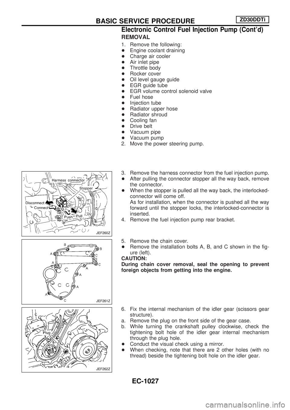
3. Remove the harness connector from the fuel injection pump.
+After pulling the connector stopper all the way back, remove
the connector.
+When the stopper is pulled all the way back, the interlocked-
connector will come off.
As for installation, when the connector is pushed all the way
forward until the stopper locks, the interlocked-connector is
inserted.
4. Remove the fuel injection pump rear bracket.
5. Remove the chain cover.
+Remove the installation bolts A, B, and C shown in the fig-
ure (left).
CAUTION:
During chain cover removal, seal the opening to prevent
foreign objects from getting into the engine.
6. Fix the internal mechanism of the idler gear (scissors gear
structure).
a. Remove the plug on the front side of the gear case.
b. While turning the crankshaft pulley clockwise, check the
tightening bolt hole of the idler gear internal mechanism
through the plug hole.
+Conduct the visual check using a mirror.
+When checking, note that there are 2 other holes (with no
thread) beside the tightening bolt hole on the idler gear.
JEF260Z
JEF261Z
JEF262Z
BASIC SERVICE PROCEDUREZD30DDTi
Electronic Control Fuel Injection Pump (Cont'd)
EC-1027
Page 349 of 1033
17 CHECK MAIN 12 CAUSES
If the cause cannot be isolated, go to ªMAIN 12 CAUSES OF OVERHEATINGº, EC-1116.
cINSPECTION END
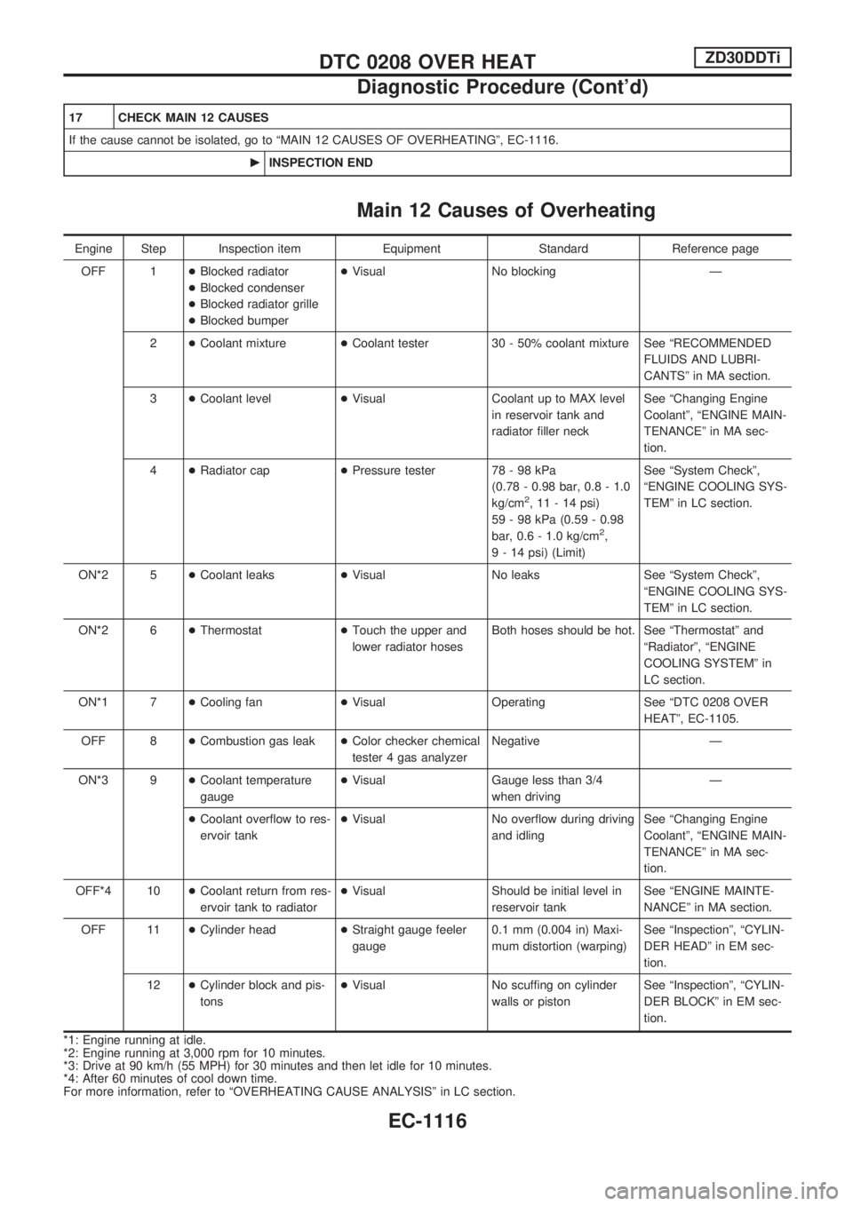
Main 12 Causes of Overheating
Engine Step Inspection item Equipment Standard Reference page
OFF 1+Blocked radiator
+Blocked condenser
+Blocked radiator grille
+Blocked bumper+Visual No blocking Ð
2+Coolant mixture+Coolant tester 30 - 50% coolant mixture See ªRECOMMENDED
FLUIDS AND LUBRI-
CANTSº in MA section.
3+Coolant level+Visual Coolant up to MAX level
in reservoir tank and
radiator filler neckSee ªChanging Engine
Coolantº, ªENGINE MAIN-
TENANCEº in MA sec-
tion.
4+Radiator cap+Pressure tester 78 - 98 kPa
(0.78 - 0.98 bar, 0.8 - 1.0
kg/cm
2, 11 - 14 psi)
59 - 98 kPa (0.59 - 0.98
bar, 0.6 - 1.0 kg/cm
2,
9 - 14 psi) (Limit)See ªSystem Checkº,
ªENGINE COOLING SYS-
TEMº in LC section.
ON*2 5+Coolant leaks+Visual No leaks See ªSystem Checkº,
ªENGINE COOLING SYS-
TEMº in LC section.
ON*2 6+Thermostat+Touch the upper and
lower radiator hosesBoth hoses should be hot. See ªThermostatº and
ªRadiatorº, ªENGINE
COOLING SYSTEMº in
LC section.
ON*1 7+Cooling fan+Visual Operating See ªDTC 0208 OVER
HEATº, EC-1105.
OFF 8+Combustion gas leak+Color checker chemical
tester 4 gas analyzerNegative Ð
ON*3 9+Coolant temperature
gauge+Visual Gauge less than 3/4
when drivingÐ
+Coolant overflow to res-
ervoir tank+Visual No overflow during driving
and idlingSee ªChanging Engine
Coolantº, ªENGINE MAIN-
TENANCEº in MA sec-
tion.
OFF*4 10+Coolant return from res-
ervoir tank to radiator+Visual Should be initial level in
reservoir tankSee ªENGINE MAINTE-
NANCEº in MA section.
OFF 11+Cylinder head+Straight gauge feeler
gauge0.1 mm (0.004 in) Maxi-
mum distortion (warping)See ªInspectionº, ªCYLIN-
DER HEADº in EM sec-
tion.
12+Cylinder block and pis-
tons+Visual No scuffing on cylinder
walls or pistonSee ªInspectionº, ªCYLIN-
DER BLOCKº in EM sec-
tion.
*1: Engine running at idle.
*2: Engine running at 3,000 rpm for 10 minutes.
*3: Drive at 90 km/h (55 MPH) for 30 minutes and then let idle for 10 minutes.
*4: After 60 minutes of cool down time.
For more information, refer to ªOVERHEATING CAUSE ANALYSISº in LC section.
DTC 0208 OVER HEATZD30DDTi
Diagnostic Procedure (Cont'd)
EC-1116
Page 439 of 1033
4 CHECK CHARGE AIR PRESSURE SENSOR INPUT SIGNAL CIRCUIT FOR OPEN AND SHORT
1. Disconnect ECM harness connector.
2. Check harness continuity between ECM terminal 46 and charge air pressure sensor terminal 2. Refer to Wiring Diagram.
Continuity should exist.
3. Also check harness for short to ground and short to power.
OK or NG
OKcGO TO 5.
NGcRepair open circuit or short to ground or short to power in harness or connectors.
5 CHECK CHARGE AIR PRESSURE SENSOR
1. Remove charge air pressure sensor with its harness connector connected.
2. Turn ignition switch ªONº.
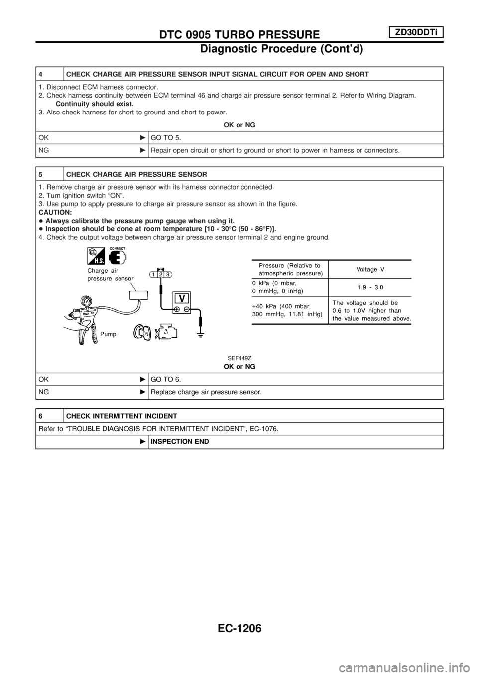
3. Use pump to apply pressure to charge air pressure sensor as shown in the figure.
CAUTION:
+Always calibrate the pressure pump gauge when using it.
+Inspection should be done at room temperature [10 - 30ÉC (50 - 86ÉF)].
4. Check the output voltage between charge air pressure sensor terminal 2 and engine ground.
SEF449Z
OK or NG
OKcGO TO 6.
NGcReplace charge air pressure sensor.
6 CHECK INTERMITTENT INCIDENT
Refer to ªTROUBLE DIAGNOSIS FOR INTERMITTENT INCIDENTº, EC-1076.
cINSPECTION END
DTC 0905 TURBO PRESSUREZD30DDTi
Diagnostic Procedure (Cont'd)
EC-1206
Page 459 of 1033
6 CHECK GLOW INDICATOR LAMP POWER SUPPLY CIRCUIT
1. Turn ignition switch ªOFFº.
2. Disconnect combination meter harness connector M32.
3. Turn ignition switch ªONº.
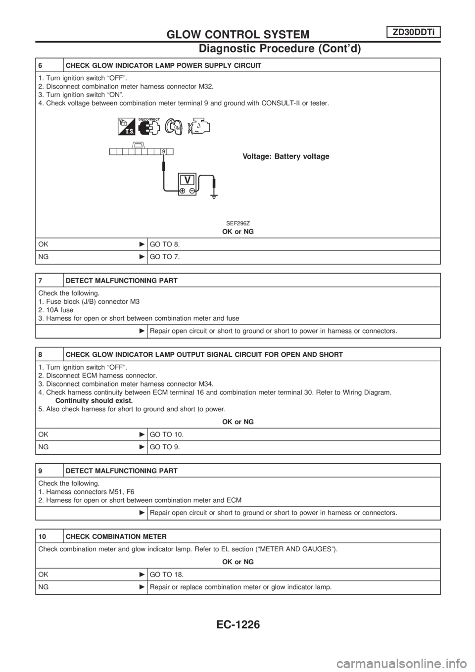
4. Check voltage between combination meter terminal 9 and ground with CONSULT-II or tester.
SEF296Z
OK or NG
OKcGO TO 8.
NGcGO TO 7.
7 DETECT MALFUNCTIONING PART
Check the following.
1. Fuse block (J/B) connector M3
2. 10A fuse
3. Harness for open or short between combination meter and fuse
cRepair open circuit or short to ground or short to power in harness or connectors.
8 CHECK GLOW INDICATOR LAMP OUTPUT SIGNAL CIRCUIT FOR OPEN AND SHORT
1. Turn ignition switch ªOFFº.
2. Disconnect ECM harness connector.
3. Disconnect combination meter harness connector M34.
4. Check harness continuity between ECM terminal 16 and combination meter terminal 30. Refer to Wiring Diagram.
Continuity should exist.
5. Also check harness for short to ground and short to power.
OK or NG
OKcGO TO 10.
NGcGO TO 9.
9 DETECT MALFUNCTIONING PART
Check the following.
1. Harness connectors M51, F6
2. Harness for open or short between combination meter and ECM
cRepair open circuit or short to ground or short to power in harness or connectors.
10 CHECK COMBINATION METER
Check combination meter and glow indicator lamp. Refer to EL section (ªMETER AND GAUGESº).
OK or NG
OKcGO TO 18.
NGcRepair or replace combination meter or glow indicator lamp.
GLOW CONTROL SYSTEMZD30DDTi
Diagnostic Procedure (Cont'd)
EC-1226