2000 NISSAN PATROL gauge
[x] Cancel search: gaugePage 881 of 1033
Engine coolant temperature sensor
(ECTS) .............................................. EC-1092
Engine oil filter replacement ................. MA-1013
Engine oil replacement ......................... MA-1012
Engine removal ..................................... EM-1064
Engine serial number ............................. GI-1008
F
F/FOG - Wiring diagram ........................ EL-1052
Final drive disassembly .............. PD-1004, 1005
Fluid temperature sensor (A/T) ............. AT-1081
Fluids .................................................... MA-1008
Flywheel runout .................................... EM-1095
Fog lamp, front ...................................... EL-1052
Fog lamp, rear ....................................... EL-1053
Forward clutch ....................................... AT-1167
Front axle .............................................. FA-1002
Front final drive disassembly (4WD) .... PD-1004
Front fog lamp ....................................... EL-1052
Front passenger air bag ....................... RS-1003
Front seat .............................................. BT-1006
Front washer .......................................... EL-1098
Front wiper ............................................. EL-1098
Fuel cut control (at no load & high
engine speed) ................................... EC-1021
Fuel filter replacement .......................... MA-1017
Fuel gauge ............................................. EL-1073
Fuel injection system ............................ EC-1019
Fuel line inspection ............................... MA-1018
Fuel precautions ..................................... GI-1002
Fuse block ............................................. EL-1229
Fuse ....................................................... EL-1230
Fusible link ............................................. EL-1230
G
GLOW - Wiring diagram ....................... EC-1221
Gauges .................................................. EL-1073
Glow plug .............................................. EC-1221
Glow relay ............................................. EC-1221
Grease ........................................ MA-1008, 1016
Ground distribution ................................ EL-1013
H
HEAT UP - Wiring diagram .................. EC-1242
HEATER - Wiring diagram .................... HA-1005
HLC - Wiring diagram ............................ EL-1099
HORN - Wiring diagram ........................ EL-1100
Harness layout ....................................... EL-1191
Hazard warning lamp ............................ EL-1058
Headlamp washer .................................. EL-1099
Headlamp wiper ..................................... EL-1099
Headlamp .............................................. EL-1044
Heat up switch ...................................... EC-1241
High clutch ............................................. AT-1165Horn ....................................................... EL-1100
How to erase DTC for OBD system ..... EC-1032
I
ILL - Wiring diagram .............................. EL-1061
Identification plate .................................. GI-1008
Idle speed ............................................. EC-1049
Illumination ............................................. EL-1060
Injection nozzle ..................................... EC-1023
Intake manifold ..................................... EM-1012
Interior lamp ........................................... EL-1067
Interior ................................................... BT-1004
J
Junction box (J/B) .................................. EL-1229
L
License lamp ......................................... EL-1046
Lifting points ........................................... GI-1009
Line pressure solenoid valve ................ AT-1086
Line pressure test (A/T) ........................ AT-1044
Liquid gasket application ...................... EM-1003
Location of electrical units ..................... EL-1185
Low and reverse brake ......................... AT-1171
Lubricants ............................................. MA-1008
Luggage room lamp .............................. EL-1067
M
MAFS - Wiring diagram ........................ EC-1086
MAIN - Wiring diagram ......................... EC-1077
MAJOR OVERHALL .............................. AT-1129
METER - Wiring diagram ...................... EL-1073
Maintenance (engine) ........................... MA-1011
Malfunction indicator lamp (MIL) .......... EC-1033
Manifold tightening torque (intake &
exhaust) ............................................ MA-1011
Mass air flow sensor (MAFS) ............... EC-1086
Meter ...................................................... EL-1073
Mirror, door ............................................ BT-1007
Mirror, outside ....................................... BT-1007
Model variation ....................................... GI-1005
N
NATS (Nissan Anti-theft System) .......... EL-1163
NATS - Wiring diagram ......................... EL-1166
NVH troubleshooting (EM) ................... EM-1008
ALPHABETICAL INDEX
IDX-1003
Page 883 of 1033
Tow truck towing .......................... GI-1009, 1010
Towing point ........................................... GI-1010
Trim ....................................................... BT-1004
Turbocharger charge air cooler ............ EM-1011
Turbocharger ........................................ EM-1014
Turn signal lamp .................................... EL-1058
V
VSS - Wiring diagram ........................... EC-1096
Vacuum hose drawing (Engine
control) ............................................... EC-1017
Valve clearance .................................... EM-1036
Valve guide ........................................... EM-1060
Valve lifter ............................................. EM-1033
Valve seat ............................................. EM-1061Valve spring .......................................... EM-1062
Vehicle identification number ....... GI-1005, 1007
Vehicle speed sensor (VSS) ................. EC-1096
W
WARN - Wiring diagram ........................ EL-1080
WINDOW - Wiring diagram ................... EL-1117
WIPER - Wiring diagram ....................... EL-1098
Warning chime ....................................... EL-1091
Warning lamps ....................................... EL-1078
Washer, front ......................................... EL-1098
Water temperature gauge ..................... EL-1073
Wiper, front ............................................ EL-1098
ALPHABETICAL INDEX
IDX-1005
Page 886 of 1033
Oil Pressure Check
WARNING:
+Be careful not to burn yourself, as the engine and oil
may be hot.
+Oil pressure check should be done in ªNeutralº gear
position.
1. Check oil level.
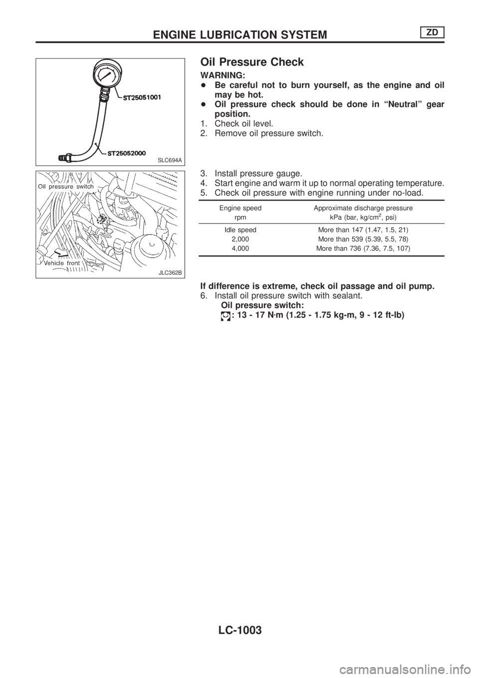
2. Remove oil pressure switch.
3. Install pressure gauge.
4. Start engine and warm it up to normal operating temperature.
5. Check oil pressure with engine running under no-load.
Engine speed
rpmApproximate discharge pressure
kPa (bar, kg/cm2, psi)
Idle speed
2,000
4,000More than 147 (1.47, 1.5, 21)
More than 539 (5.39, 5.5, 78)
More than 736 (7.36, 7.5, 107)
If difference is extreme, check oil passage and oil pump.
6. Install oil pressure switch with sealant.
Oil pressure switch:
:13-17Nzm (1.25 - 1.75 kg-m,9-12ft-lb)
SLC694A
JLC362B
ENGINE LUBRICATION SYSTEMZD
LC-1003
Page 888 of 1033
OIL PUMP INSPECTION
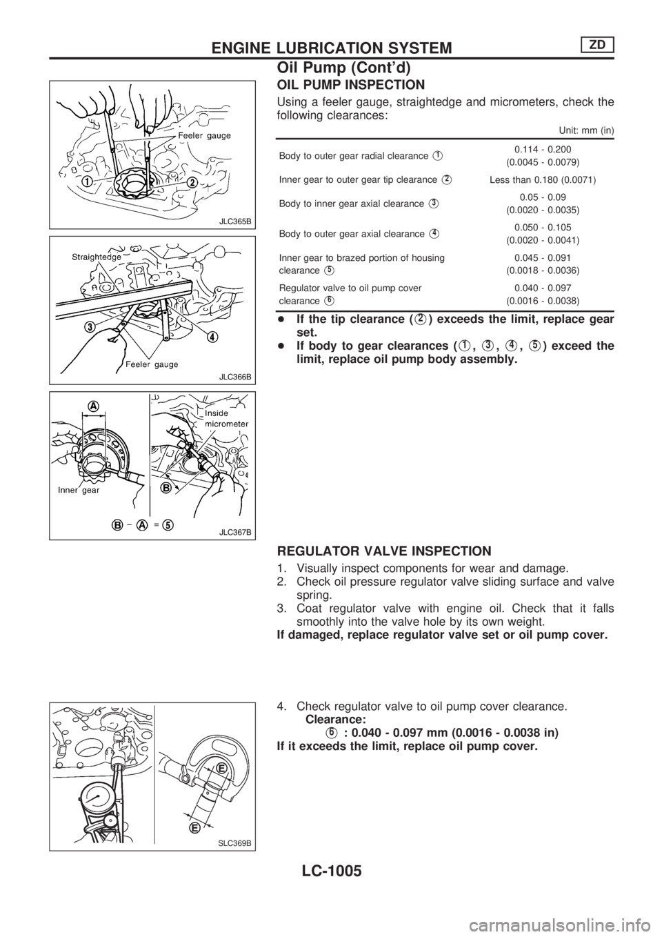
Using a feeler gauge, straightedge and micrometers, check the
following clearances:
Unit: mm (in)
Body to outer gear radial clearanceV10.114 - 0.200
(0.0045 - 0.0079)
Inner gear to outer gear tip clearance
V2Less than 0.180 (0.0071)
Body to inner gear axial clearance
V30.05 - 0.09
(0.0020 - 0.0035)
Body to outer gear axial clearance
V40.050 - 0.105
(0.0020 - 0.0041)
Inner gear to brazed portion of housing
clearance
V50.045 - 0.091
(0.0018 - 0.0036)
Regulator valve to oil pump cover
clearance
V60.040 - 0.097
(0.0016 - 0.0038)
+If the tip clearance (V2) exceeds the limit, replace gear
set.
+If body to gear clearances (
V1,V3,V4,V5) exceed the
limit, replace oil pump body assembly.
REGULATOR VALVE INSPECTION
1. Visually inspect components for wear and damage.
2. Check oil pressure regulator valve sliding surface and valve
spring.
3. Coat regulator valve with engine oil. Check that it falls
smoothly into the valve hole by its own weight.
If damaged, replace regulator valve set or oil pump cover.
4. Check regulator valve to oil pump cover clearance.
Clearance:
V6: 0.040 - 0.097 mm (0.0016 - 0.0038 in)
If it exceeds the limit, replace oil pump cover.
JLC365B
JLC366B
JLC367B
SLC369B
ENGINE LUBRICATION SYSTEMZD
Oil Pump (Cont'd)
LC-1005
Page 914 of 1033
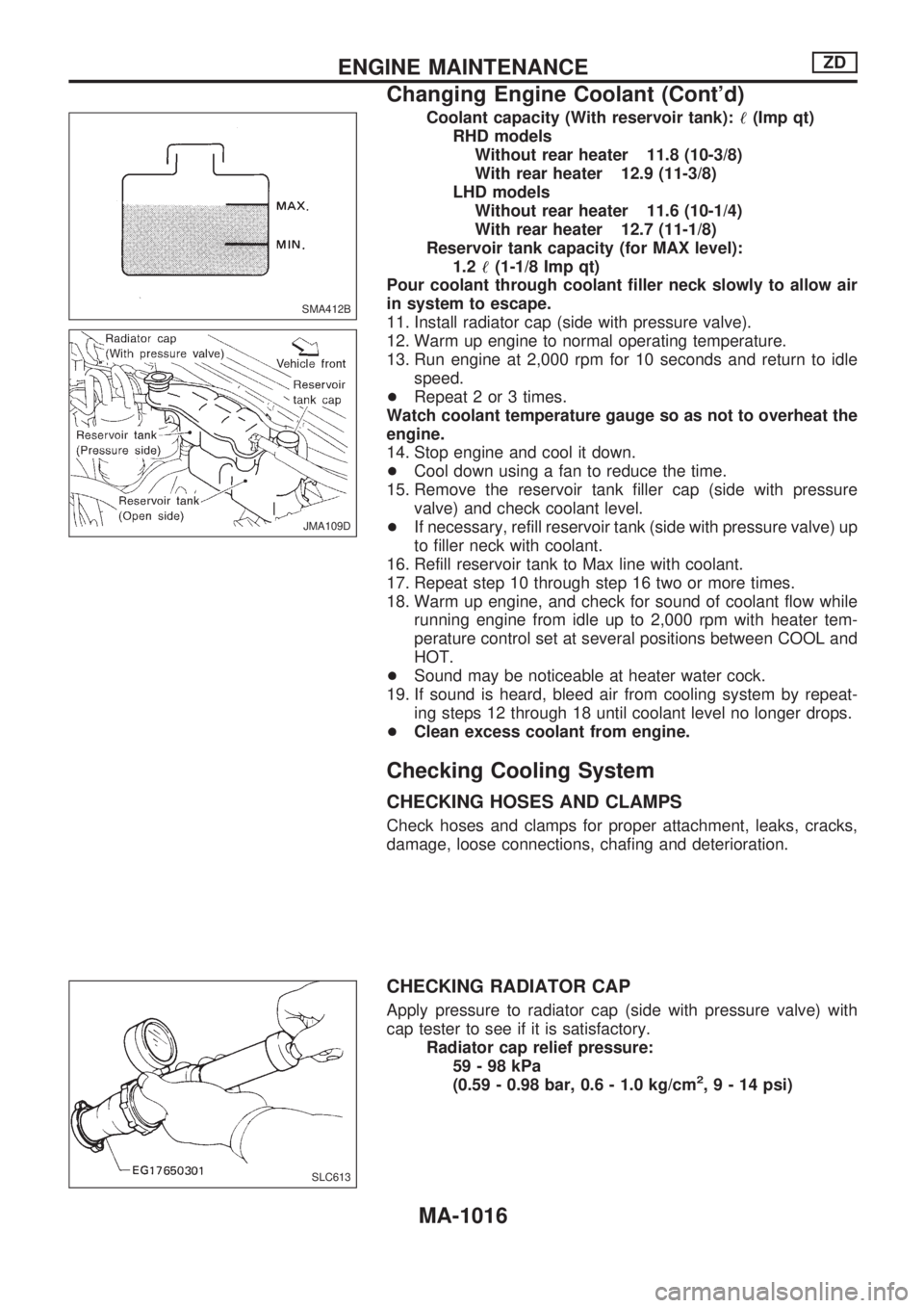
Coolant capacity (With reservoir tank):!(Imp qt)
RHD models
Without rear heater 11.8 (10-3/8)
With rear heater 12.9 (11-3/8)
LHD models
Without rear heater 11.6 (10-1/4)
With rear heater 12.7 (11-1/8)
Reservoir tank capacity (for MAX level):
1.2!(1-1/8 Imp qt)
Pour coolant through coolant filler neck slowly to allow air
in system to escape.
11. Install radiator cap (side with pressure valve).
12. Warm up engine to normal operating temperature.
13. Run engine at 2,000 rpm for 10 seconds and return to idle
speed.
+Repeat 2 or 3 times.
Watch coolant temperature gauge so as not to overheat the
engine.
14. Stop engine and cool it down.
+Cool down using a fan to reduce the time.
15. Remove the reservoir tank filler cap (side with pressure
valve) and check coolant level.
+If necessary, refill reservoir tank (side with pressure valve) up
to filler neck with coolant.
16. Refill reservoir tank to Max line with coolant.
17. Repeat step 10 through step 16 two or more times.
18. Warm up engine, and check for sound of coolant flow while
running engine from idle up to 2,000 rpm with heater tem-
perature control set at several positions between COOL and
HOT.
+Sound may be noticeable at heater water cock.
19. If sound is heard, bleed air from cooling system by repeat-
ing steps 12 through 18 until coolant level no longer drops.
+Clean excess coolant from engine.
Checking Cooling System
CHECKING HOSES AND CLAMPS
Check hoses and clamps for proper attachment, leaks, cracks,
damage, loose connections, chafing and deterioration.
CHECKING RADIATOR CAP
Apply pressure to radiator cap (side with pressure valve) with
cap tester to see if it is satisfactory.
Radiator cap relief pressure:
59-98kPa
(0.59 - 0.98 bar, 0.6 - 1.0 kg/cm
2,9-14psi)
SMA412B
JMA109D
SLC613
ENGINE MAINTENANCEZD
Changing Engine Coolant (Cont'd)
MA-1016
Page 918 of 1033
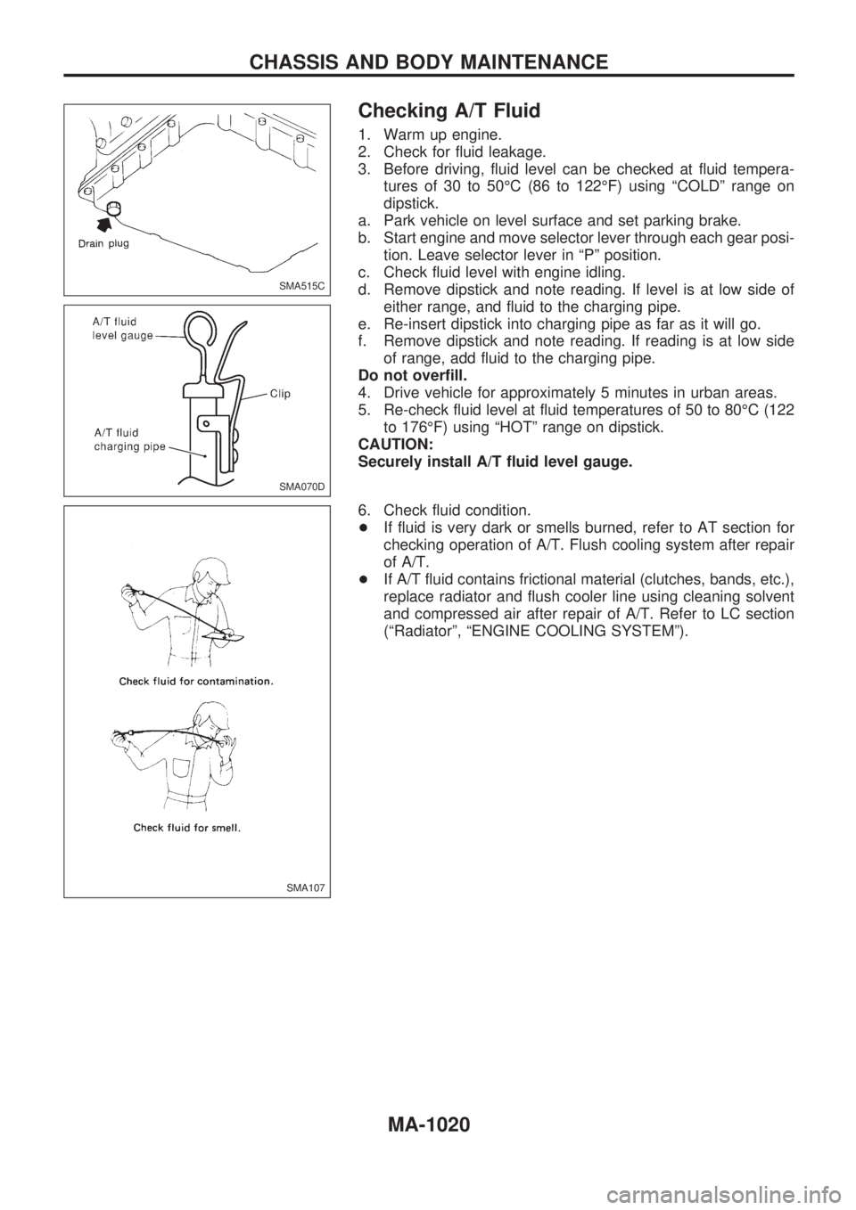
Checking A/T Fluid
1. Warm up engine.
2. Check for fluid leakage.
3. Before driving, fluid level can be checked at fluid tempera-
tures of 30 to 50ÉC (86 to 122ÉF) using ªCOLDº range on
dipstick.
a. Park vehicle on level surface and set parking brake.
b. Start engine and move selector lever through each gear posi-
tion. Leave selector lever in ªPº position.
c. Check fluid level with engine idling.
d. Remove dipstick and note reading. If level is at low side of
either range, and fluid to the charging pipe.
e. Re-insert dipstick into charging pipe as far as it will go.
f. Remove dipstick and note reading. If reading is at low side
of range, add fluid to the charging pipe.
Do not overfill.
4. Drive vehicle for approximately 5 minutes in urban areas.
5. Re-check fluid level at fluid temperatures of 50 to 80ÉC (122
to 176ÉF) using ªHOTº range on dipstick.
CAUTION:
Securely install A/T fluid level gauge.
6. Check fluid condition.
+If fluid is very dark or smells burned, refer to AT section for
checking operation of A/T. Flush cooling system after repair
of A/T.
+If A/T fluid contains frictional material (clutches, bands, etc.),
replace radiator and flush cooler line using cleaning solvent
and compressed air after repair of A/T. Refer to LC section
(ªRadiatorº, ªENGINE COOLING SYSTEMº).
SMA515C
SMA070D
SMA107
CHASSIS AND BODY MAINTENANCE
MA-1020
Page 938 of 1033
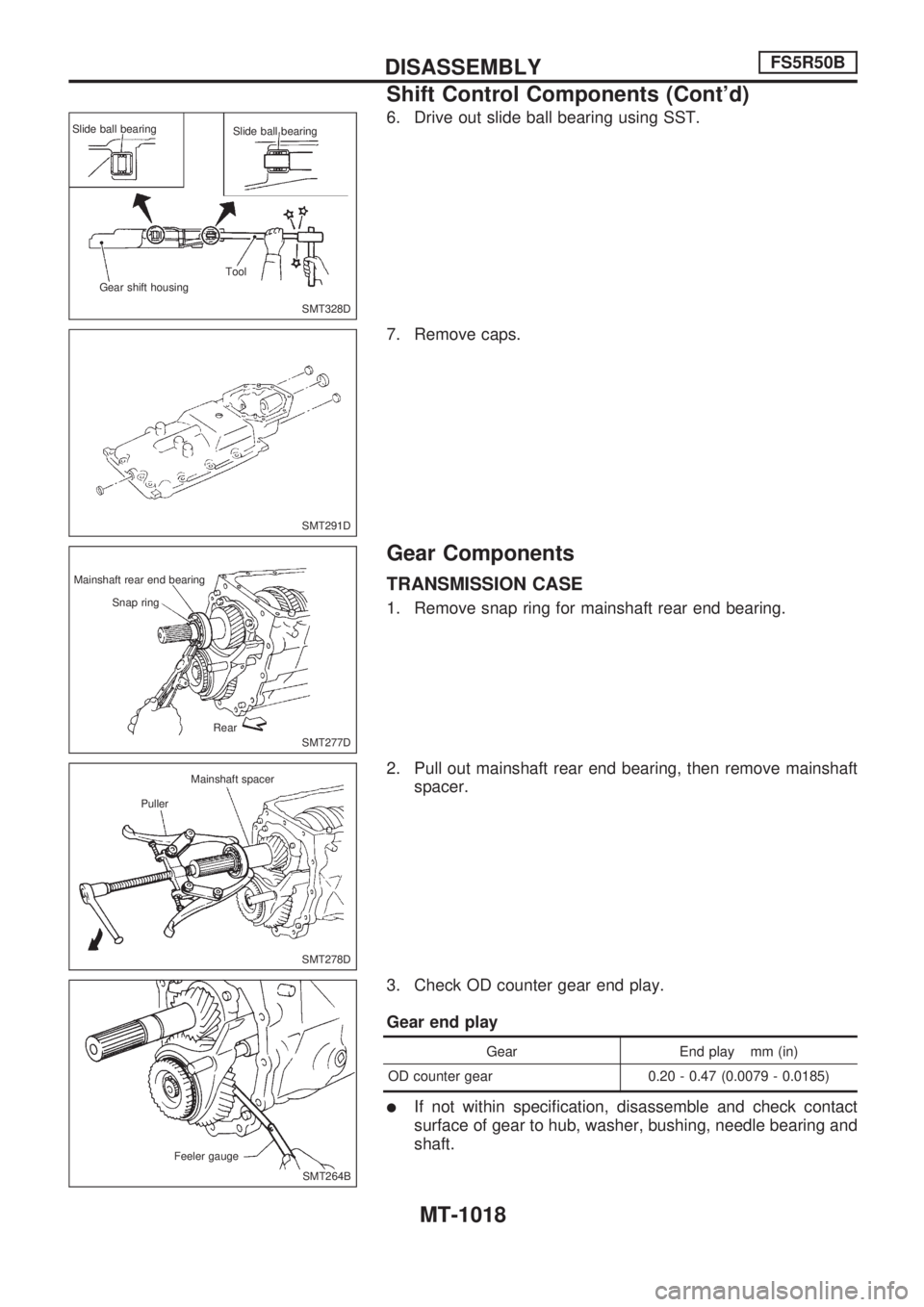
6. Drive out slide ball bearing using SST.
7. Remove caps.
Gear Components
TRANSMISSION CASE
1. Remove snap ring for mainshaft rear end bearing.
2. Pull out mainshaft rear end bearing, then remove mainshaft
spacer.
3. Check OD counter gear end play.
Gear end play
Gear End play mm (in)
OD counter gear 0.20 - 0.47 (0.0079 - 0.0185)
lIf not within specification, disassemble and check contact
surface of gear to hub, washer, bushing, needle bearing and
shaft.
SMT328D Slide ball bearing
Slide ball bearing
Tool
Gear shift housing
SMT291D
SMT277D Mainshaft rear end bearing
Snap ring
Rear
SMT278D Mainshaft spacer
Puller
SMT264B Feeler gauge
DISASSEMBLYFS5R50B
Shift Control Components (Cont'd)
MT-1018
Page 941 of 1033
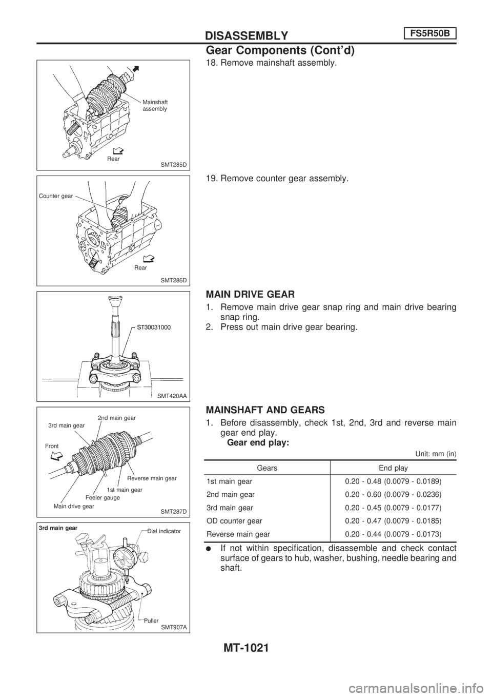
18. Remove mainshaft assembly.
19. Remove counter gear assembly.
MAIN DRIVE GEAR
1. Remove main drive gear snap ring and main drive bearing
snap ring.
2. Press out main drive gear bearing.
MAINSHAFT AND GEARS
1. Before disassembly, check 1st, 2nd, 3rd and reverse main
gear end play.
Gear end play:
Unit: mm (in)
Gears End play
1st main gear 0.20 - 0.48 (0.0079 - 0.0189)
2nd main gear 0.20 - 0.60 (0.0079 - 0.0236)
3rd main gear 0.20 - 0.45 (0.0079 - 0.0177)
OD counter gear 0.20 - 0.47 (0.0079 - 0.0185)
Reverse main gear 0.20 - 0.44 (0.0079 - 0.0173)
lIf not within specification, disassemble and check contact
surface of gears to hub, washer, bushing, needle bearing and
shaft.
SMT285D Mainshaft
assembly
Rear
SMT286D Counter gear
Rear
SMT420AA
SMT287D 2nd main gear
3rd main gear
Front
Main drive gearFeeler gauge1st main gearReverse main gear
SMT907A 3rd main gear
Dial indicator
Puller
DISASSEMBLYFS5R50B
Gear Components (Cont'd)
MT-1021