2000 NISSAN PATROL maintenance
[x] Cancel search: maintenancePage 1 of 1033
Edition: February 2000
Release: February 2000 (01)
Publication No.: SM0E-Y61AE0E
Reference No.: 7711346024GENERAL INFORMATIONGI
MAINTENANCEMA
ENGINE MECHANICALEM
ENGINE LUBRICATION &
COOLING SYSTEMSLC
ENGINE CONTROL SYSTEMEC
ACCELERATOR CONTROL,
FUEL & EXHAUST SYSTEMFE
CLUTCHCL
MANUAL TRANSMISSIONMT
AUTOMATIC TRANSMISSIONAT
TRANSFERTF
PROPELLER SHAFT &
DIFFERENTIAL CARRIERPD
FRONT AXLE & FRONT SUSPENSIONFA
REAR AXLE & REAR SUSPENSIONRA
BRAKE SYSTEMBR
STEERING SYSTEMST
RESTRAINT SYSTEMRS
BODY & TRIMBT
HEATER & AIR CONDITIONERHA
ELECTRICAL SYSTEMEL
ALPHABETICAL INDEXIDX
PATROL GR
MODEL Y61 SERIES
NISSAN EUROPE S.A.S.
2000 NISSAN EUROPE S.A.S.
Produced in The Netherlands
Not to be reproduced in whole or in part
without the prior written permission of
Nissan Europe S.A.S., Paris, France.
QUICK REFERENCE INDEX
Page 2 of 1033

FOREWORD
This manual contains maintenance and repair procedures for NISSAN
PATROL GR,modelY61 series.
In order to assure your safety and the efficient functioning of the vehicle,
this manual should be read thoroughly. It is especially important that the
PRECAUTIONS in the GI section be completely understood before starting
any repair task.
All information in this manual is based on the latest product information
at the time of publication. The right is reserved to make changes in speci-
®cations and methods at any time without notice.
IMPORTANT SAFETY NOTICE
The proper performance of service is essential for both the safety of the
technician and the efficient functioning of the vehicle.
The service methods in this Service Manual are described in such a man-
ner that the service may be performed safely and accurately.
Service varies with the procedures used, the skills of the technician and the
tools and parts available. Accordingly, anyone using service procedures,
tools or parts which are not speci®cally recommended by NISSAN must
®rst completely satisfy himself that neither his safety nor the vehicle's
safety will be jeopardized by the service method selected.
NISSAN EUROPE S.A.S.
Service Engineering SectionParis, France
Page 6 of 1033
Tool number
Tool nameDescription
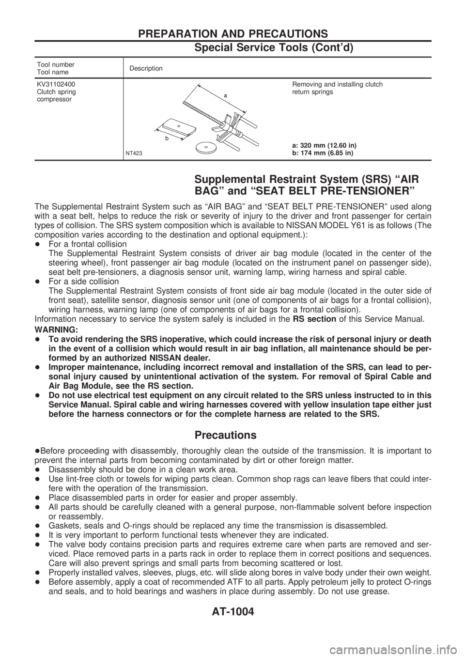
KV31102400
Clutch spring
compressor
NT423
Removing and installing clutch
return springs
a: 320 mm (12.60 in)
b: 174 mm (6.85 in)
Supplemental Restraint System (SRS) ªAIR
BAGº and ªSEAT BELT PRE-TENSIONERº
The Supplemental Restraint System such as ªAIR BAGº and ªSEAT BELT PRE-TENSIONERº used along
with a seat belt, helps to reduce the risk or severity of injury to the driver and front passenger for certain
types of collision. The SRS system composition which is available to NISSAN MODEL Y61 is as follows (The
composition varies according to the destination and optional equipment.):
+For a frontal collision
The Supplemental Restraint System consists of driver air bag module (located in the center of the
steering wheel), front passenger air bag module (located on the instrument panel on passenger side),
seat belt pre-tensioners, a diagnosis sensor unit, warning lamp, wiring harness and spiral cable.
+For a side collision
The Supplemental Restraint System consists of front side air bag module (located in the outer side of
front seat), satellite sensor, diagnosis sensor unit (one of components of air bags for a frontal collision),
wiring harness, warning lamp (one of components of air bags for a frontal collision).
Information necessary to service the system safely is included in theRS sectionof this Service Manual.
WARNING:
+To avoid rendering the SRS inoperative, which could increase the risk of personal injury or death
in the event of a collision which would result in air bag inflation, all maintenance should be per-
formed by an authorized NISSAN dealer.
+Improper maintenance, including incorrect removal and installation of the SRS, can lead to per-
sonal injury caused by unintentional activation of the system. For removal of Spiral Cable and
Air Bag Module, see the RS section.
+Do not use electrical test equipment on any circuit related to the SRS unless instructed to in this
Service Manual. Spiral cable and wiring harnesses covered with yellow insulation tape either just
before the harness connectors or for the complete harness are related to the SRS.
Precautions
+Before proceeding with disassembly, thoroughly clean the outside of the transmission. It is important to
prevent the internal parts from becoming contaminated by dirt or other foreign matter.
+Disassembly should be done in a clean work area.
+Use lint-free cloth or towels for wiping parts clean. Common shop rags can leave fibers that could inter-
fere with the operation of the transmission.
+Place disassembled parts in order for easier and proper assembly.
+All parts should be carefully cleaned with a general purpose, non-flammable solvent before inspection
or reassembly.
+Gaskets, seals and O-rings should be replaced any time the transmission is disassembled.
+It is very important to perform functional tests whenever they are indicated.
+The valve body contains precision parts and requires extreme care when parts are removed and ser-
viced. Place removed parts in a parts rack in order to replace them in correct positions and sequences.
Care will also prevent springs and small parts from becoming scattered or lost.
+Properly installed valves, sleeves, plugs, etc. will slide along bores in valve body under their own weight.
+Before assembly, apply a coat of recommended ATF to all parts. Apply petroleum jelly to protect O-rings
and seals, and to hold bearings and washers in place during assembly. Do not use grease.
PREPARATION AND PRECAUTIONS
Special Service Tools (Cont'd)
AT-1004
Page 43 of 1033
A/T Fluid Check
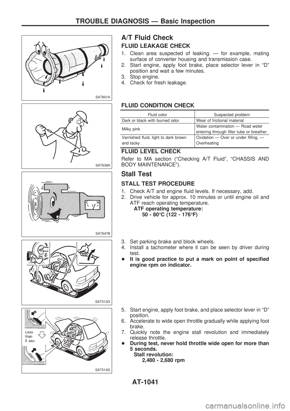
FLUID LEAKAGE CHECK
1. Clean area suspected of leaking. Ð for example, mating
surface of converter housing and transmission case.
2. Start engine, apply foot brake, place selector lever in ªDº
position and wait a few minutes.
3. Stop engine.
4. Check for fresh leakage.
FLUID CONDITION CHECK
Fluid color Suspected problem
Dark or black with burned odor Wear of frictional material
Milky pinkWater contamination Ð Road water
entering through filler tube or breather
Varnished fluid, light to dark brown
and tackyOxidation Ð Over or under filling, Ð
Overheating
FLUID LEVEL CHECK
Refer to MA section (ªChecking A/T Fluidº, ªCHASSIS AND
BODY MAINTENANCEº).
Stall Test
STALL TEST PROCEDURE
1. Check A/T and engine fluid levels. If necessary, add.
2. Drive vehicle for approx. 10 minutes or until engine oil and
ATF reach operating temperature.
ATF operating temperature:
50 - 80ÉC (122 - 176ÉF)
3. Set parking brake and block wheels.
4. Install a tachometer where it can be seen by driver during
test.
+It is good practice to put a mark on point of specified
engine rpm on indicator.
5. Start engine, apply foot brake, and place selector lever in ªDº
position.
6. Accelerate to wide open throttle gradually while applying foot
brake.
7. Quickly note the engine stall revolution and immediately
release throttle.
+During test, never hold throttle wide open for more than
5 seconds.
Stall revolution:
2,480 - 2,680 rpm
SAT801A
SAT638A
SAT647B
SAT513G
SAT514G
TROUBLE DIAGNOSIS Ð Basic Inspection
AT-1041
Page 207 of 1033
A/T Fluid Cooler
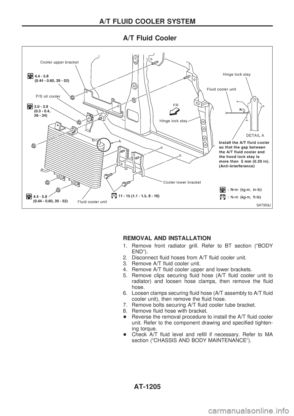
REMOVAL AND INSTALLATION
1. Remove front radiator grill. Refer to BT section (ªBODY
ENDº).
2. Disconnect fluid hoses from A/T fluid cooler unit.
3. Remove A/T fluid cooler unit.
4. Remove A/T fluid cooler upper and lower brackets.
5. Remove clips securing fluid hose (A/T fluid cooler unit to
radiator) and loosen hose clamps, then remove the fluid
hose.
6. Loosen clamps securing fluid hose (A/T assembly to A/T fluid
cooler unit), then remove the fluid hose.
7. Remove bolts securing A/T fluid cooler tube bracket.
8. Remove fluid hose with bracket.
+Reverse the removal procedure to install the A/T fluid cooler
unit. Refer to the component drawing and specified tighten-
ing torque.
+Check A/T fluid level and refill if necessary. Refer to MA
section (ªCHASSIS AND BODY MAINTENANCEº).
SAT959J
A/T FLUID COOLER SYSTEM
AT-1205
Page 224 of 1033
Supplemental Restraint System (SRS) ªAIR
BAGº and ªSEAT BELT PRE-TENSIONERº
The Supplemental Restraint System such as ªAIR BAGº and ªSEAT BELT PRE-TENSIONERº used along
with a seat belt, helps to reduce the risk or severity of injury to the driver and front passenger for certain
types of collision. The SRS system composition which is available to NISSAN MODEL Y61 is as follows (The
composition varies according to the destination and optional equipment.):
+For a frontal collision
The Supplemental Restraint System consists of driver air bag module (located in the center of the
steering wheel), front passenger air bag module (located on the instrument panel on passenger side),
seat belt pre-tensioners, a diagnosis sensor unit, warning lamp, wiring harness and spiral cable.
+ For a side collision
The Supplemental Restraint System consists of front side air bag module (located in the outer side of
front seat), satellite sensor, diagnosis sensor unit (one of components of air bags for a frontal collision),
wiring harness, warning lamp (one of components of air bags for a frontal collision).
Information necessary to service the system safely is included in the RS sectionof this Service Manual.
WARNING:
+ To avoid rendering the SRS inoperative, which could increase the risk of personal injury or death
in the event of a collision which would result in air bag inflation, all maintenance should be per-
formed by an authorized NISSAN dealer.
+ Improper maintenance, including incorrect removal and installation of the SRS, can lead to per-
sonal injury caused by intentional activation of the system. For removal of Spiral Cable and Air
Bag Module, see the RS section.
+ Do not use electrical test equipment on any circuit related to the SRS unless instructed to in this
Service Manual. Spiral cable and wiring harnesses covered with yellow insulation tape either just
before the harness connectors or for the complete harness are related to the SRS.
PRECAUTIONS
BT-1002
Page 238 of 1033
Special Service Tool
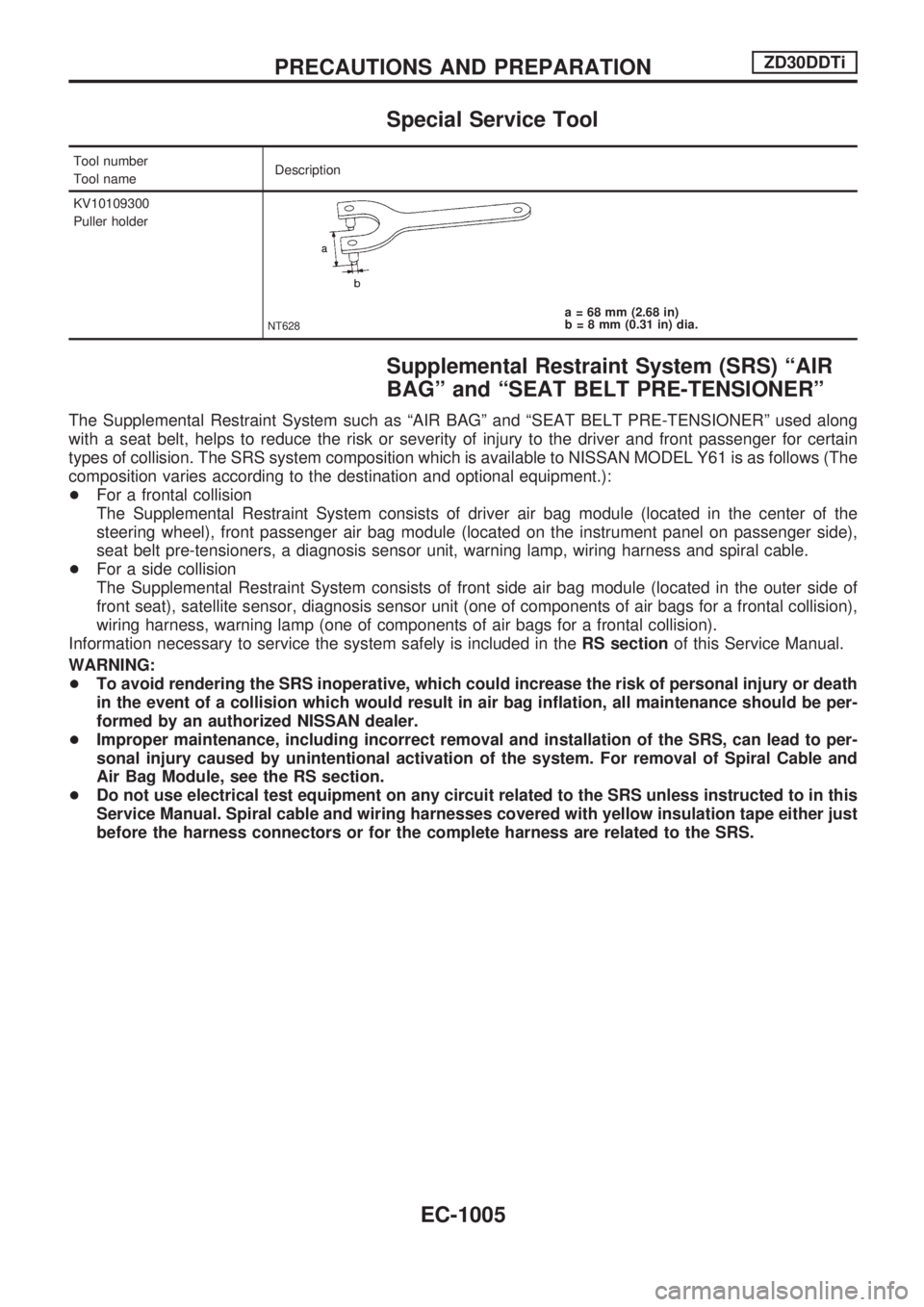
Tool number
Tool nameDescription
KV10109300
Puller holder
NT628a = 68 mm (2.68 in)
b = 8 mm (0.31 in) dia.
Supplemental Restraint System (SRS) ªAIR
BAGº and ªSEAT BELT PRE-TENSIONERº
The Supplemental Restraint System such as ªAIR BAGº and ªSEAT BELT PRE-TENSIONERº used along
with a seat belt, helps to reduce the risk or severity of injury to the driver and front passenger for certain
types of collision. The SRS system composition which is available to NISSAN MODEL Y61 is as follows (The
composition varies according to the destination and optional equipment.):
+For a frontal collision
The Supplemental Restraint System consists of driver air bag module (located in the center of the
steering wheel), front passenger air bag module (located on the instrument panel on passenger side),
seat belt pre-tensioners, a diagnosis sensor unit, warning lamp, wiring harness and spiral cable.
+For a side collision
The Supplemental Restraint System consists of front side air bag module (located in the outer side of
front seat), satellite sensor, diagnosis sensor unit (one of components of air bags for a frontal collision),
wiring harness, warning lamp (one of components of air bags for a frontal collision).
Information necessary to service the system safely is included in theRS sectionof this Service Manual.
WARNING:
+To avoid rendering the SRS inoperative, which could increase the risk of personal injury or death
in the event of a collision which would result in air bag inflation, all maintenance should be per-
formed by an authorized NISSAN dealer.
+Improper maintenance, including incorrect removal and installation of the SRS, can lead to per-
sonal injury caused by unintentional activation of the system. For removal of Spiral Cable and
Air Bag Module, see the RS section.
+Do not use electrical test equipment on any circuit related to the SRS unless instructed to in this
Service Manual. Spiral cable and wiring harnesses covered with yellow insulation tape either just
before the harness connectors or for the complete harness are related to the SRS.
PRECAUTIONS AND PREPARATIONZD30DDTi
EC-1005
Page 282 of 1033
Basic Inspection
Precaution:
Perform Basic Inspection without electrical or mechanical
loads applied;
+Shift lever is in neutral position,
+Heat up switch is OFF,
+Headlamp switch is OFF,
+Air conditioner switch is OFF,
+Rear defogger switch is OFF,
+Steering wheel is in the straight-ahead position, etc.
1 INSPECTION START
1. Check service records for any recent repairs that may indicate a related problem.
2. Check the current need for scheduled maintenance, especially for fuel filter and air cleaner filter. Refer to MA section.
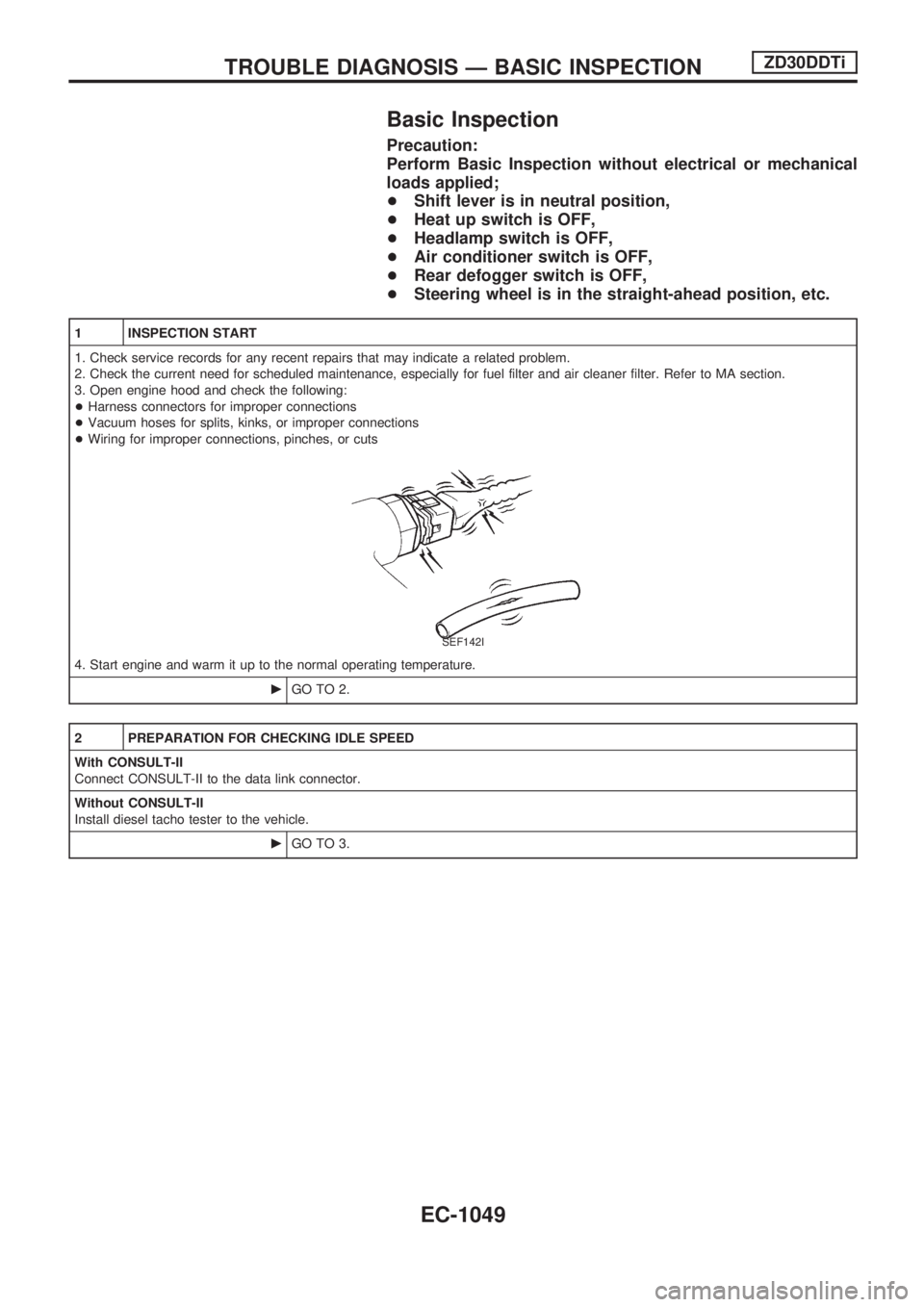
3. Open engine hood and check the following:
+Harness connectors for improper connections
+Vacuum hoses for splits, kinks, or improper connections
+Wiring for improper connections, pinches, or cuts
SEF142I
4. Start engine and warm it up to the normal operating temperature.
cGO TO 2.
2 PREPARATION FOR CHECKING IDLE SPEED
With CONSULT-II
Connect CONSULT-II to the data link connector.
Without CONSULT-II
Install diesel tacho tester to the vehicle.
cGO TO 3.
TROUBLE DIAGNOSIS Ð BASIC INSPECTIONZD30DDTi
EC-1049