Page 919 of 1033
Changing A/T Fluid
1. Warm up A/T fluid.
2. Stop engine.
3. Drain A/T fluid from drain plug and refill with new A/T fluid.
Always refill same volume with drained fluid.
Fluid grade:
Genuine Nissan ATF or equivalent. Refer to ªREC-
OMMENDED FLUIDS AND LUBRICANTSº,
MA-1008.
Fluid capacity (With torque converter):
11.8!(10-3/8 Imp qt)
Drain plug:
:29-39Nzm (3.0 - 4.0 kg-m, 22 - 29 ft-lb)
4. Run engine at idle speed for five minutes.
5. Check fluid level and condition. Refer to ªChecking A/T
Fluidº. If fluid is still dirty, repeat steps 2 through 5.
SMA515C
CHASSIS AND BODY MAINTENANCE
MA-1021
Page 920 of 1033
Engine Maintenance (ZD)
INSPECTION AND ADJUSTMENT
Oil capacity (Refill capacity)
Unit:!(Imp qt)
With oil filter change 5.7 (5)
Without oil filter change 5.2 (4-5/8)
Cooling system check
Unit: kPa (bar, kg/cm2, psi)
Cooling system testing pressure 98 (0.98, 1.0, 14)
Radiator cap relief pressure59-98
(0.59 - 0.98, 0.6 - 1.0,9-14)
SERVICE DATA AND SPECIFICATIONS (SDS)
MA-1022
Page 925 of 1033
NVH Troubleshooting Chart
Use the chart below to help you find the cause of the symptom. The numbers indicate the order of the
inspection. If necessary, repair or replace these parts.
Reference page
FS5R50B
Refer to MA section (``Checking M/T Oil'',
``CHASSIS AND BODY MAINTENANCE'').
MT-1011
MT-1011
MT-1014
MT-1014
MT-1012
MT-1012
MT-1012
MT-1012
SUSPECTED PARTS
(Possible cause)
Transmission model
OIL (Level low)
OIL (Wrong)
OIL (Level too high)
LIQUID GASKET (Damaged)
OIL SEAL (Worn or damaged)
CHECK PLUG RETURN SPRING AND
CHECK BALL (Worn or damaged)
SHIFT FORK (Worn)
GEAR (Worn or damaged)
BEARING (Worn or damaged)
BAULK RING (Worn or damaged)
INSERT SPRING (Damaged)
SymptomNoise 1 2 3 3
Oil leakage3122
Hard to shift or will not shift 1 1 2 2
Jumps out of gear 1 2 2
NOISE, VIBRATION AND HARSHNESS (NVH)
TROUBLESHOOTINGFS5R50B
MT-1005
Page 973 of 1033

RESTRAINT SYSTEM
SECTION
RS
MODIFICATION NOTICE:
+Side air bag has been adopted as optional equipment.
+Diagnosis sensor unit has been changed.
+Seat belt pre-tensioner with load limiter has been added.
+Deployment procedure of seat belt pre-tensioner has been changed.
CONTENTS
PRECAUTION...................................................... 1002
Supplemental Restraint System (SRS) ªAIR
BAGº and ªSEAT BELT PRE-TENSIONERº ... 1002
SUPPLEMENTAL RESTRAINT SYSTEM (SRS)1003
Precautions for SRS ªAIR BAGº and ªSEAT
BELT PRE-TENSIONERº Service ................... 1003
Special Service Tools ...................................... 1003
Description ....................................................... 1004
Built-in Type Side Air Bag ............................... 1004
Seat Belt Pre-tensioner with Load Limiter ....... 1005
SRS Component Parts Location...................... 1005
Maintenance Items........................................... 1006
Removal and Installation Ð Diagnosis Sensor
Unit, Seat Belt Pre-tensioner with Load Limiter
and Satellite Sensor......................................... 1008
Removal Ð Driver Air Bag Module and Spiral
Cable ................................................................ 1009Installation Ð Driver Air Bag Module and
Spiral Cable ..................................................... 1011
Removal Ð Side Air Bag Module.................... 1012
Installation Ð Side Air Bag Module................. 1013
Disposal of Air Bag Module and Seat Belt
Pre-tensioner.................................................... 1015
TROUBLE DIAGNOSES Ð Supplemental
Restraint System (SRS)..................................... 1019
Trouble Diagnoses Introduction ....................... 1019
How to Perform Trouble Diagnoses for Quick
and Accurate Repair ........................................ 1021
Schematic ........................................................ 1023
Wiring Diagram Ð SRS Ð/LHD Models ......... 1024
Wiring Diagram Ð SRS Ð/RHD Models ........ 1028
Self-diagnosis................................................... 1032
Trouble Diagnoses for Air Bag Warning Lamp1050
COLLISION DIAGNOSIS..................................... 1052
RS
Page 974 of 1033

Supplemental Restraint System (SRS) ªAIR
BAGº and ªSEAT BELT PRE-TENSIONERº
The Supplemental Restraint System such as ªAIR BAGº and ªSEAT BELT PRE-TENSIONERº used along
with a seat belt, helps to reduce the risk or severity of injury to the driver and front passenger for certain
types of collision. The SRS composition which is available to NISSAN MODEL Y61 is as follows (The com-
position varies according to the destination and optional equipment.):
+For a frontal collision
The Supplemental Restraint System consists of driver air bag module (located in the center of the
steering wheel), front passenger air bag module (located on the instrument panel on passenger side),
seat belt pre-tensioners, a diagnosis sensor unit, warning lamp, wiring harness and spiral cable.
+For a side collision
The Supplemental Restraint System consists of front side air bag module (located in the outer side of
front seat), satellite sensor, diagnosis sensor unit (one of components of air bags for a frontal collision),
wiring harness, warning lamp (one of components of air bags for a frontal collision).
WARNING:
+To avoid rendering the SRS inoperative, which could increase the risk of personal injury or death
in the event of a collision which would result in air bag inflation, all maintenance should be per-
formed by an authorized NISSAN dealer.
+Improper maintenance, including incorrect removal and installation of the SRS, can lead to per-
sonal injury caused by unintentional activation of the system.
+Do not use electrical test equipment on any circuit related to the SRS unless instructed to in this
Service Manual. Spiral cable and wiring harnesses covered with yellow insulation tape either just
before the harness connectors or for the complete harness are related to the SRS.
PRECAUTION
RS-1002
Page 978 of 1033

Maintenance Items
CAUTION:
Do not use electrical test equipment to check SRS circuit.
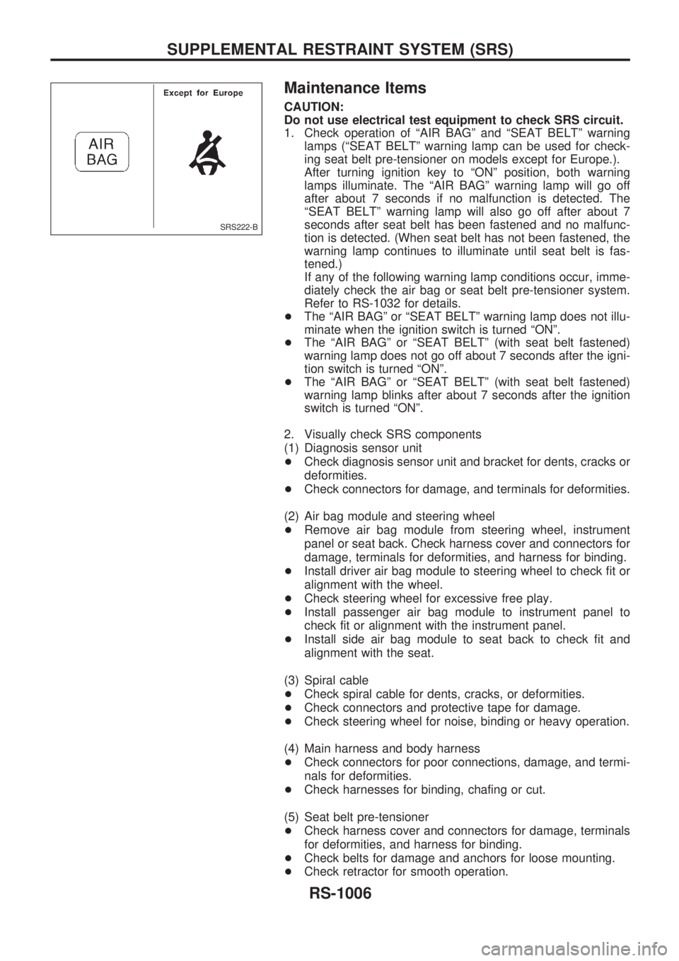
1. Check operation of ªAIR BAGº and ªSEAT BELTº warning
lamps (ªSEAT BELTº warning lamp can be used for check-
ing seat belt pre-tensioner on models except for Europe.).
After turning ignition key to ªONº position, both warning
lamps illuminate. The ªAIR BAGº warning lamp will go off
after about 7 seconds if no malfunction is detected. The
ªSEAT BELTº warning lamp will also go off after about 7
seconds after seat belt has been fastened and no malfunc-
tion is detected. (When seat belt has not been fastened, the
warning lamp continues to illuminate until seat belt is fas-
tened.)
If any of the following warning lamp conditions occur, imme-
diately check the air bag or seat belt pre-tensioner system.
Refer to RS-1032 for details.
+The ªAIR BAGº or ªSEAT BELTº warning lamp does not illu-
minate when the ignition switch is turned ªONº.
+The ªAIR BAGº or ªSEAT BELTº (with seat belt fastened)
warning lamp does not go off about 7 seconds after the igni-
tion switch is turned ªONº.
+The ªAIR BAGº or ªSEAT BELTº (with seat belt fastened)
warning lamp blinks after about 7 seconds after the ignition
switch is turned ªONº.
2. Visually check SRS components
(1) Diagnosis sensor unit
+Check diagnosis sensor unit and bracket for dents, cracks or
deformities.
+Check connectors for damage, and terminals for deformities.
(2) Air bag module and steering wheel
+Remove air bag module from steering wheel, instrument
panel or seat back. Check harness cover and connectors for
damage, terminals for deformities, and harness for binding.
+Install driver air bag module to steering wheel to check fit or
alignment with the wheel.
+Check steering wheel for excessive free play.
+Install passenger air bag module to instrument panel to
check fit or alignment with the instrument panel.
+Install side air bag module to seat back to check fit and
alignment with the seat.
(3) Spiral cable
+Check spiral cable for dents, cracks, or deformities.
+Check connectors and protective tape for damage.
+Check steering wheel for noise, binding or heavy operation.
(4) Main harness and body harness
+Check connectors for poor connections, damage, and termi-
nals for deformities.
+Check harnesses for binding, chafing or cut.
(5) Seat belt pre-tensioner
+Check harness cover and connectors for damage, terminals
for deformities, and harness for binding.
+Check belts for damage and anchors for loose mounting.
+Check retractor for smooth operation.
SRS222-B
SUPPLEMENTAL RESTRAINT SYSTEM (SRS)
RS-1006
Page 979 of 1033
+Perform self-diagnosis for seat belt pre-tensioner using seat
belt warning lamp or CONSULT-II. Refer to ªSelf-diagnosisº
for details.
(6) Satellite sensor
+Check satellite sensor (including bracket portion) for dents,
cracks or deformities.
+Check connectors for damage, and terminals for deformities.
CAUTION:
Replace previously used special bolts, ground bolt and nuts
coated with bonding agent.
SUPPLEMENTAL RESTRAINT SYSTEM (SRS)
Maintenance Items (Cont'd)
RS-1007
Page 1012 of 1033
DIAGNOSTIC PROCEDURE 4 (Continued from
DIAGNOSTIC PROCEDURE 2)
Inspecting SRS malfunctioning record
Is it the first time for maintenance of
SRS?
Yes
cNo
ªSELF-DIAG [PAST]º
(which was previously
entered) is still retained in
memory.
Go to DIAGNOSTIC PRO-
CEDURE 3 (RS-1038).
Go to DIAGNOSTIC PROCEDURE 5
(RS-1040).
DIAGNOSTIC PROCEDURE 5 (with CONSULT-II)
Inspecting SRS intermittent malfunction by using CON-
SULT-II Ð Diagnosis mode
1. Turn ignition switch ªOFFº.
2. Connect CONSULT-II to data link connector.
3. Turn ignition switch ªONº.
4. Touch ªSTARTº.
5. Touch ªAIR BAGº.
SRS468-A
SRS695
SRS771
.
TROUBLE DIAGNOSES Ð Supplemental Restraint System (SRS)
Self-diagnosis (Cont'd)
RS-1040