Page 780 of 1033
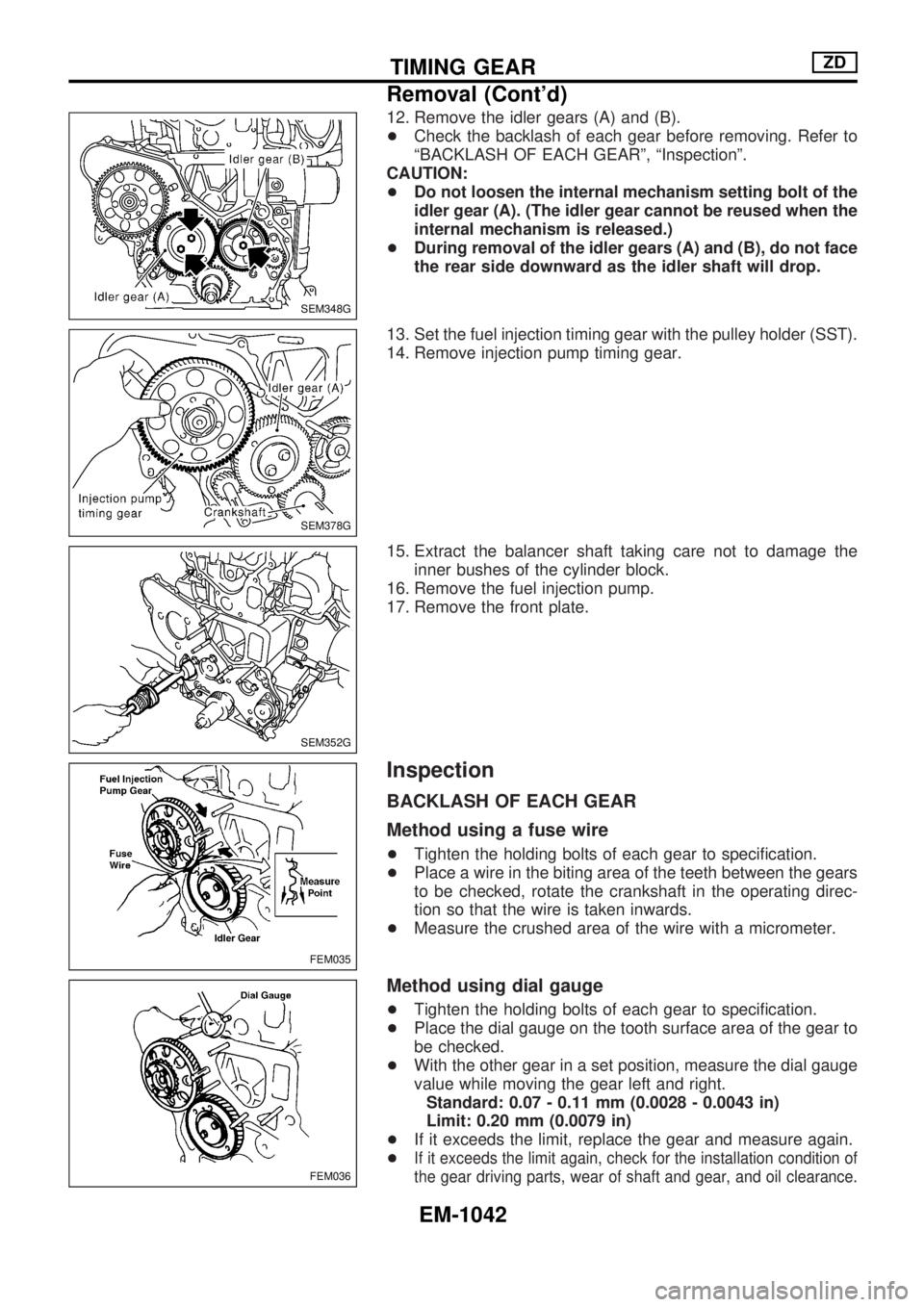
12. Remove the idler gears (A) and (B).
+Check the backlash of each gear before removing. Refer to
ªBACKLASH OF EACH GEARº, ªInspectionº.
CAUTION:
+Do not loosen the internal mechanism setting bolt of the
idler gear (A). (The idler gear cannot be reused when the
internal mechanism is released.)
+During removal of the idler gears (A) and (B), do not face
the rear side downward as the idler shaft will drop.
13. Set the fuel injection timing gear with the pulley holder (SST).
14. Remove injection pump timing gear.
15. Extract the balancer shaft taking care not to damage the
inner bushes of the cylinder block.
16. Remove the fuel injection pump.
17. Remove the front plate.
Inspection
BACKLASH OF EACH GEAR
Method using a fuse wire
+Tighten the holding bolts of each gear to specification.
+Place a wire in the biting area of the teeth between the gears
to be checked, rotate the crankshaft in the operating direc-
tion so that the wire is taken inwards.
+Measure the crushed area of the wire with a micrometer.
Method using dial gauge
+Tighten the holding bolts of each gear to specification.
+Place the dial gauge on the tooth surface area of the gear to
be checked.
+With the other gear in a set position, measure the dial gauge
value while moving the gear left and right.
Standard: 0.07 - 0.11 mm (0.0028 - 0.0043 in)
Limit: 0.20 mm (0.0079 in)
+If it exceeds the limit, replace the gear and measure again.
+
If it exceeds the limit again, check for the installation condition of
the gear driving parts, wear of shaft and gear, and oil clearance.
SEM348G
SEM378G
SEM352G
FEM035
FEM036
TIMING GEARZD
Removal (Cont'd)
EM-1042
Page 781 of 1033
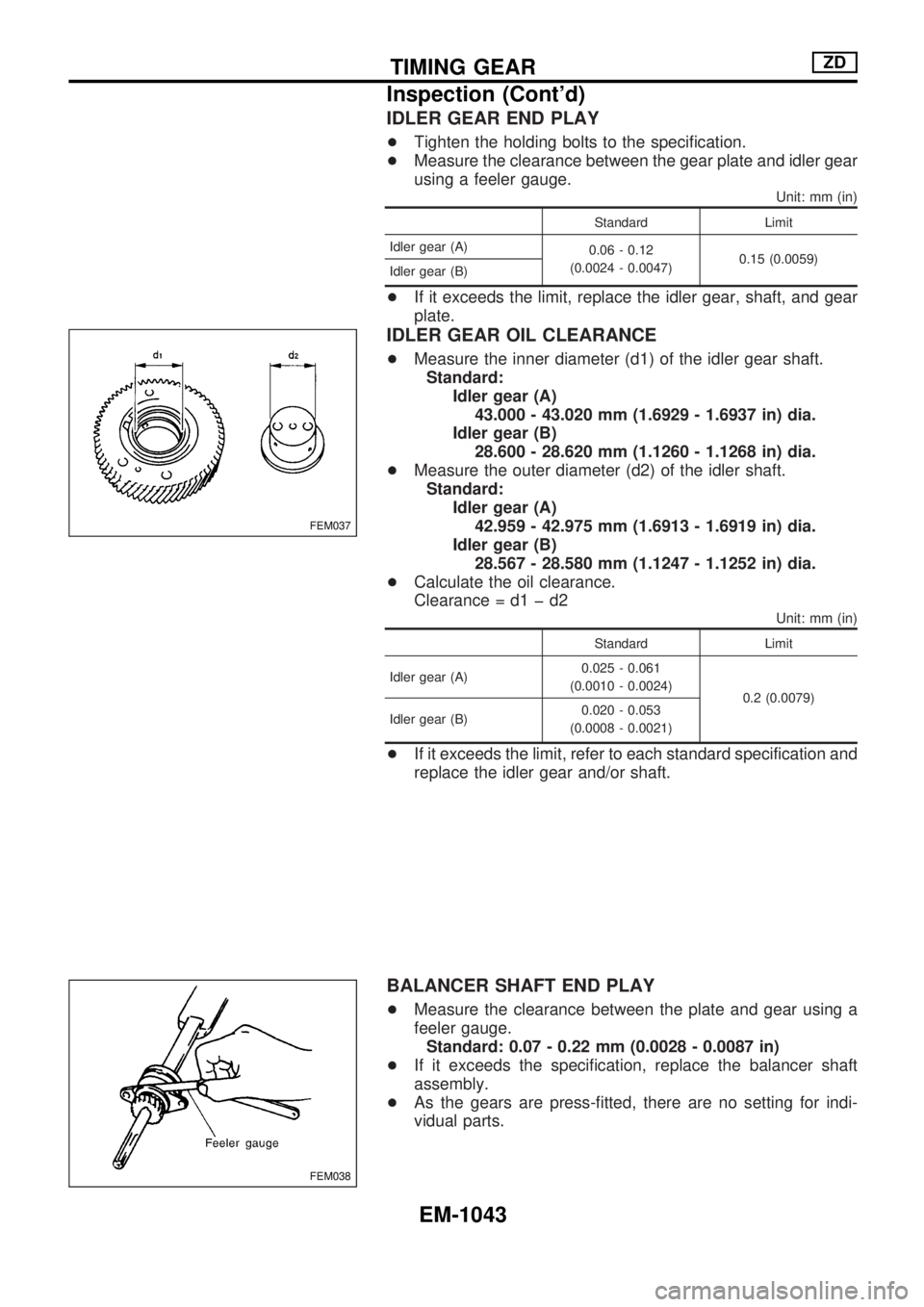
IDLER GEAR END PLAY
+Tighten the holding bolts to the specification.
+Measure the clearance between the gear plate and idler gear
using a feeler gauge.
Unit: mm (in)
Standard Limit
Idler gear (A)
0.06 - 0.12
(0.0024 - 0.0047)0.15 (0.0059)
Idler gear (B)
+If it exceeds the limit, replace the idler gear, shaft, and gear
plate.
IDLER GEAR OIL CLEARANCE
+Measure the inner diameter (d1) of the idler gear shaft.
Standard:
Idler gear (A)
43.000 - 43.020 mm (1.6929 - 1.6937 in) dia.
Idler gear (B)
28.600 - 28.620 mm (1.1260 - 1.1268 in) dia.
+Measure the outer diameter (d2) of the idler shaft.
Standard:
Idler gear (A)
42.959 - 42.975 mm (1.6913 - 1.6919 in) dia.
Idler gear (B)
28.567 - 28.580 mm (1.1247 - 1.1252 in) dia.
+Calculate the oil clearance.
Clearance = d1 þ d2
Unit: mm (in)
Standard Limit
Idler gear (A)0.025 - 0.061
(0.0010 - 0.0024)
0.2 (0.0079)
Idler gear (B)0.020 - 0.053
(0.0008 - 0.0021)
+If it exceeds the limit, refer to each standard specification and
replace the idler gear and/or shaft.
BALANCER SHAFT END PLAY
+Measure the clearance between the plate and gear using a
feeler gauge.
Standard: 0.07 - 0.22 mm (0.0028 - 0.0087 in)
+If it exceeds the specification, replace the balancer shaft
assembly.
+As the gears are press-fitted, there are no setting for indi-
vidual parts.
FEM037
FEM038
TIMING GEARZD
Inspection (Cont'd)
EM-1043
Page 782 of 1033
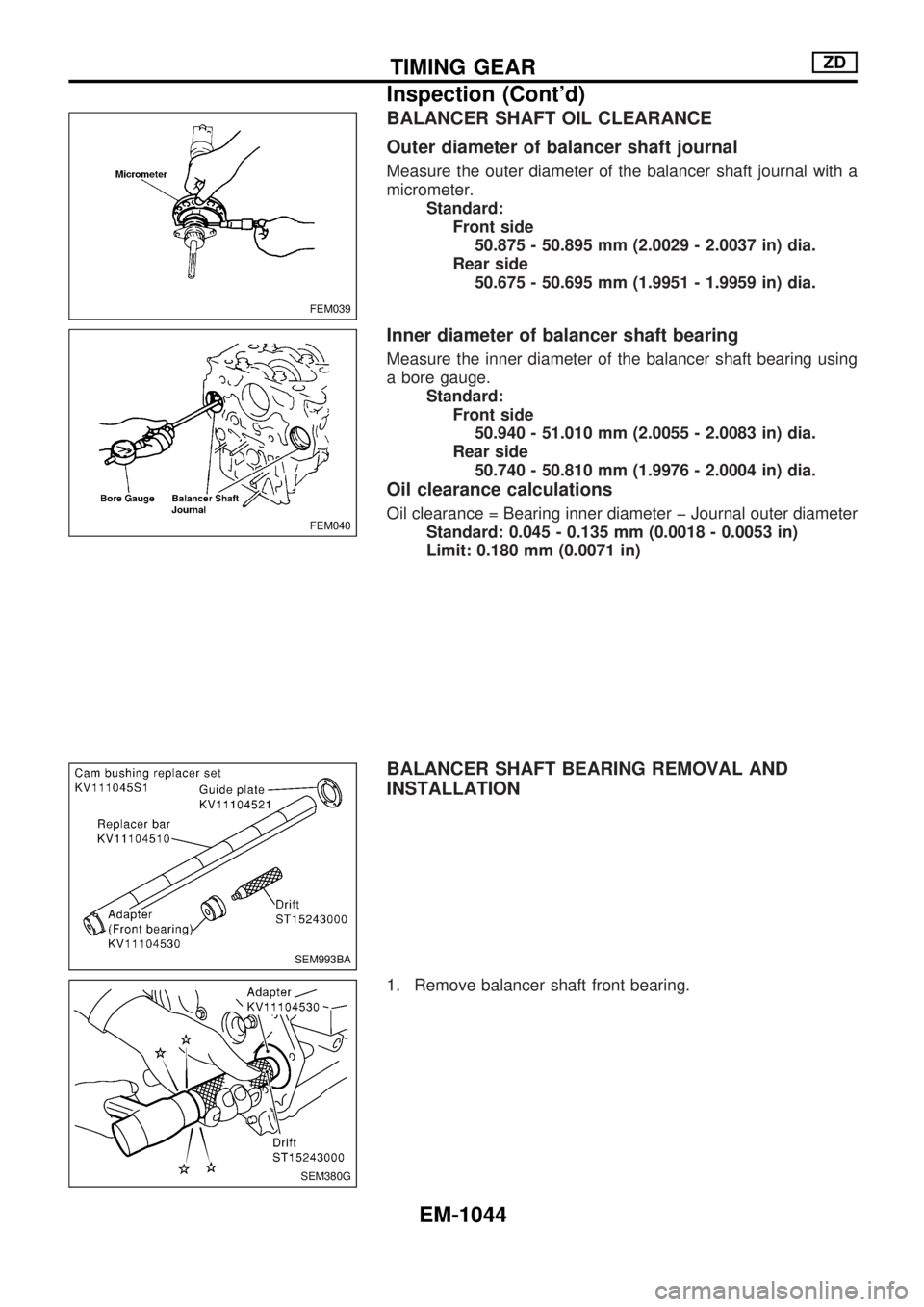
BALANCER SHAFT OIL CLEARANCE
Outer diameter of balancer shaft journal
Measure the outer diameter of the balancer shaft journal with a
micrometer.
Standard:
Front side
50.875 - 50.895 mm (2.0029 - 2.0037 in) dia.
Rear side
50.675 - 50.695 mm (1.9951 - 1.9959 in) dia.
Inner diameter of balancer shaft bearing
Measure the inner diameter of the balancer shaft bearing using
a bore gauge.
Standard:
Front side
50.940 - 51.010 mm (2.0055 - 2.0083 in) dia.
Rear side
50.740 - 50.810 mm (1.9976 - 2.0004 in) dia.
Oil clearance calculations
Oil clearance = Bearing inner diameter þ Journal outer diameter
Standard: 0.045 - 0.135 mm (0.0018 - 0.0053 in)
Limit: 0.180 mm (0.0071 in)
BALANCER SHAFT BEARING REMOVAL AND
INSTALLATION
1. Remove balancer shaft front bearing.
FEM039
FEM040
SEM993BA
SEM380G
TIMING GEARZD
Inspection (Cont'd)
EM-1044
Page 792 of 1033
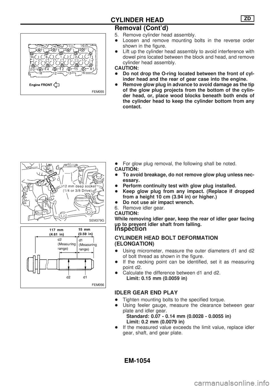
5. Remove cylinder head assembly.
+Loosen and remove mounting bolts in the reverse order
shown in the figure.
+Lift up the cylinder head assembly to avoid interference with
dowel pins located between the block and head, and remove
cylinder head assembly.
CAUTION:
+Do not drop the O-ring located between the front of cyl-
inder head and the rear of gear case into the engine.
+Remove glow plug in advance to avoid damage as the tip
of the glow plug projects from the bottom of the cylin-
der head, or, place wood blocks beneath both ends of
the cylinder head to keep the cylinder bottom from any
contact.
+For glow plug removal, the following shall be noted.
CAUTION:
+To avoid breakage, do not remove glow plug unless nec-
essary.
+Perform continuity test with glow plug installed.
+Keep glow plug from any impact. (Replace if dropped
from a height 10 cm (3.94 in) or higher.)
+Do not use air impact wrench.
6. Remove idler gear.
CAUTION:
While removing idler gear, keep the rear of idler gear facing
up to prevent idler shaft from falling.
Inspection
CYLINDER HEAD BOLT DEFORMATION
(ELONGATION)
+Using micrometer, measure the outer diameters d1 and d2
of bolt thread as shown in the figure.
+If the necking point can be identified, set it as measuring
point d2.
+Calculate the difference between d1 and d2.
Limit: 0.15 mm (0.0059 in)
IDLER GEAR END PLAY
+Tighten mounting bolts to the specified torque.
+Using feeler gauge, measure the clearance between gear
plate and idler gear.
Standard: 0.07 - 0.14 mm (0.0028 - 0.0055 in)
Limit: 0.2 mm (0.0079 in)
+If the measured value exceeds the limit value, replace idler
gear, shaft, and gear plate.
FEM055
SEM379G
FEM056
CYLINDER HEADZD
Removal (Cont'd)
EM-1054
Page 797 of 1033
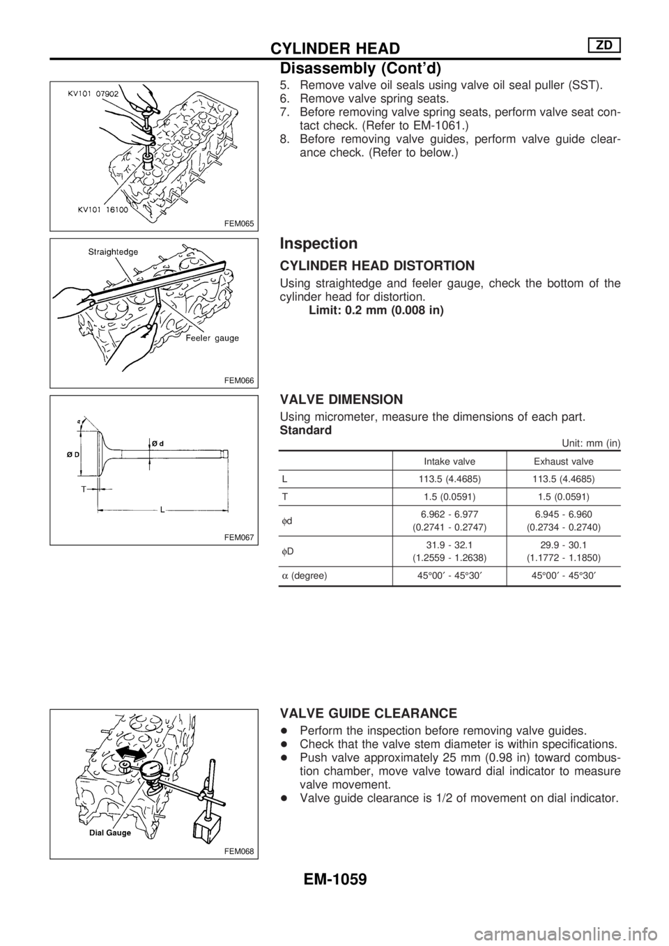
5. Remove valve oil seals using valve oil seal puller (SST).
6. Remove valve spring seats.
7. Before removing valve spring seats, perform valve seat con-
tact check. (Refer to EM-1061.)
8. Before removing valve guides, perform valve guide clear-
ance check. (Refer to below.)
Inspection
CYLINDER HEAD DISTORTION
Using straightedge and feeler gauge, check the bottom of the
cylinder head for distortion.
Limit: 0.2 mm (0.008 in)
VALVE DIMENSION
Using micrometer, measure the dimensions of each part.
Standard
Unit: mm (in)
Intake valve Exhaust valve
L 113.5 (4.4685) 113.5 (4.4685)
T 1.5 (0.0591) 1.5 (0.0591)
fd6.962 - 6.977
(0.2741 - 0.2747)6.945 - 6.960
(0.2734 - 0.2740)
fD31.9 - 32.1
(1.2559 - 1.2638)29.9 - 30.1
(1.1772 - 1.1850)
a(degree) 45É00¢- 45É30¢45É00¢- 45É30¢
VALVE GUIDE CLEARANCE
+Perform the inspection before removing valve guides.
+Check that the valve stem diameter is within specifications.
+Push valve approximately 25 mm (0.98 in) toward combus-
tion chamber, move valve toward dial indicator to measure
valve movement.
+Valve guide clearance is 1/2 of movement on dial indicator.
FEM065
FEM066
FEM067
FEM068
CYLINDER HEADZD
Disassembly (Cont'd)
EM-1059
Page 810 of 1033
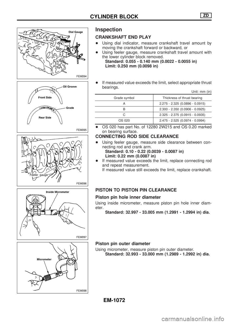
Inspection
CRANKSHAFT END PLAY
+Using dial indicator, measure crankshaft travel amount by
moving the crankshaft forward or backward, or
+Using feeler gauge, measure crankshaft travel amount with
the lower cylinder block removed.
Standard: 0.055 - 0.140 mm (0.0022 - 0.0055 in)
Limit: 0.250 mm (0.0098 in)
+If measured value exceeds the limit, select appropriate thrust
bearings.
Unit: mm (in)
Grade symbol Thickness of thrust bearing
A 2.275 - 2.325 (0.0896 - 0.0915)
B 2.300 - 2.350 (0.0906 - 0.0925)
C 2.325 - 2.375 (0.0915 - 0.0935)
OS 020 2.475 - 2.525 (0.0974 - 0.0994)
+OS 020 has part No. of 12280 2W215 and OS 0.20 marked
on bearing surface.
CONNECTING ROD SIDE CLEARANCE
+Using feeler gauge, measure side clearance between con-
necting rod and crank arm.
Standard: 0.10 - 0.22 (0.0039 - 0.0087 in)
Limit: 0.22 mm (0.0087 in)
+If measured value exceeds the limit, replace connecting rod
and repeat measurement.
If measured value still exceeds the limit, replace crankshaft.
PISTON TO PISTON PIN CLEARANCE
Piston pin hole inner diameter
Using inside micrometer, measure piston pin hole inner diam-
eter.
Standard: 32.997 - 33.005 mm (1.2991 - 1.2994 in) dia.
Piston pin outer diameter
Using micrometer, measure piston pin outer diameter.
Standard: 32.993 - 33.000 mm (1.2989 - 1.2992 in) dia.
FEM094
FEM095
FEM096
FEM097
FEM098
CYLINDER BLOCKZD
EM-1072
Page 811 of 1033
Calculation of piston to piston pin clearance
Piston pin clearance = Piston pin hole inner diameter þ Piston pin
outer diameter
Standard: þ0.003 (Tightening clearance) to 0.012 mm
(þ0.0001 to 0.0005 in)
If out of specifications, replace piston and piston pin assembly.
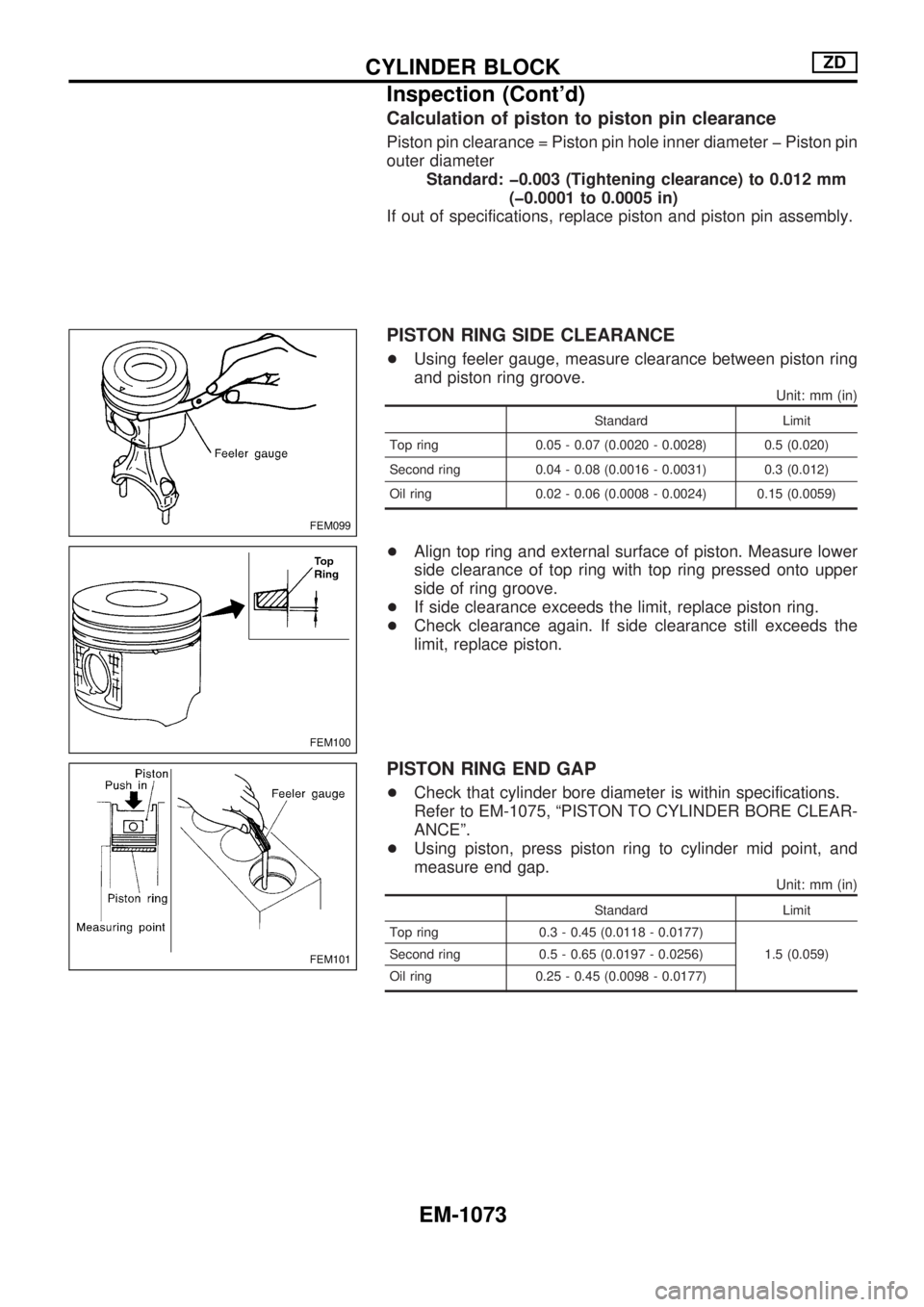
PISTON RING SIDE CLEARANCE
+Using feeler gauge, measure clearance between piston ring
and piston ring groove.
Unit: mm (in)
Standard Limit
Top ring 0.05 - 0.07 (0.0020 - 0.0028) 0.5 (0.020)
Second ring 0.04 - 0.08 (0.0016 - 0.0031) 0.3 (0.012)
Oil ring 0.02 - 0.06 (0.0008 - 0.0024) 0.15 (0.0059)
+Align top ring and external surface of piston. Measure lower
side clearance of top ring with top ring pressed onto upper
side of ring groove.
+If side clearance exceeds the limit, replace piston ring.
+Check clearance again. If side clearance still exceeds the
limit, replace piston.
PISTON RING END GAP
+Check that cylinder bore diameter is within specifications.
Refer to EM-1075, ªPISTON TO CYLINDER BORE CLEAR-
ANCEº.
+Using piston, press piston ring to cylinder mid point, and
measure end gap.
Unit: mm (in)
Standard Limit
Top ring 0.3 - 0.45 (0.0118 - 0.0177)
1.5 (0.059) Second ring 0.5 - 0.65 (0.0197 - 0.0256)
Oil ring 0.25 - 0.45 (0.0098 - 0.0177)
FEM099
FEM100
FEM101
CYLINDER BLOCKZD
Inspection (Cont'd)
EM-1073
Page 813 of 1033
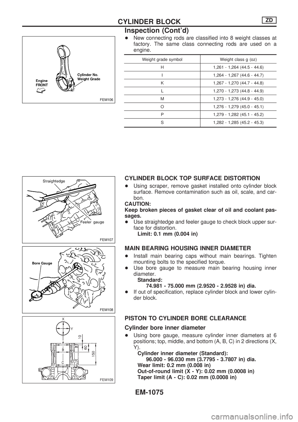
+New connecting rods are classified into 8 weight classes at
factory. The same class connecting rods are used on a
engine.
Weight grade symbol Weight class g (oz)
H 1,261 - 1,264 (44.5 - 44.6)
I 1,264 - 1,267 (44.6 - 44.7)
K 1,267 - 1,270 (44.7 - 44.8)
L 1,270 - 1,273 (44.8 - 44.9)
M 1,273 - 1,276 (44.9 - 45.0)
O 1,276 - 1,279 (45.0 - 45.1)
P 1,279 - 1,282 (45.1 - 45.2)
S 1,282 - 1,285 (45.2 - 45.3)
CYLINDER BLOCK TOP SURFACE DISTORTION
+Using scraper, remove gasket installed onto cylinder block
surface. Remove contamination such as oil, scale, and car-
bon.
CAUTION:
Keep broken pieces of gasket clear of oil and coolant pas-
sages.
+Use straightedge and feeler gauge to check block upper sur-
face for distortion.
Limit: 0.1 mm (0.004 in)
MAIN BEARING HOUSING INNER DIAMETER
+Install main bearing caps without main bearings. Tighten
mounting bolts to the specified torque.
+Use bore gauge to measure main bearing housing inner
diameter.
Standard:
74.981 - 75.000 mm (2.9520 - 2.9528 in) dia.
+If out of specification, replace cylinder block and lower cylin-
der block.
PISTON TO CYLINDER BORE CLEARANCE
Cylinder bore inner diameter
+Using bore gauge, measure cylinder inner diameters at 6
positions; top, middle, and bottom (A, B, C) in 2 directions (X,
Y).
Cylinder inner diameter (Standard):
96.000 - 96.030 mm (3.7795 - 3.7807 in) dia.
Wear limit: 0.2 mm (0.008 in)
Out-of-round limit (X - Y): 0.02 mm (0.0008 in)
Taper limit (A - C): 0.02 mm (0.0008 in)
FEM106
FEM107
FEM108
FEM109
CYLINDER BLOCKZD
Inspection (Cont'd)
EM-1075