2000 NISSAN PATROL relay
[x] Cancel search: relayPage 120 of 1033
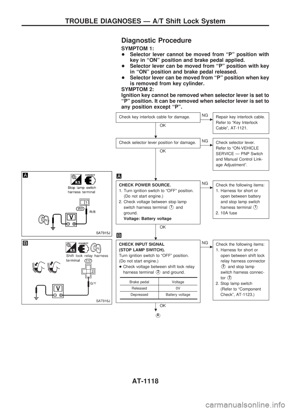
Diagnostic Procedure
SYMPTOM 1:
+Selector lever cannot be moved from ªPº position with
key in ªONº position and brake pedal applied.
+Selector lever can be moved from ªPº position with key
in ªONº position and brake pedal released.
+Selector lever can be moved from ªPº position when key
is removed from key cylinder.
SYMPTOM 2:
Ignition key cannot be removed when selector lever is set to
ªPº position. It can be removed when selector lever is set to
any position except ªPº.
Check key interlock cable for damage.
OK
cNG
Repair key interlock cable.
Refer to ªKey Interlock
Cableº, AT-1121.
Check selector lever position for damage.
OK
cNG
Check selector lever.
Refer to ªON-VEHICLE
SERVICE Ð PNP Switch
and Manual Control Link-
age Adjustmentº.
CHECK POWER SOURCE.
1. Turn ignition switch to ªOFFº position.
(Do not start engine.)
2. Check voltage between stop lamp
switch harness terminal
V1and
ground.
Voltage: Battery voltage
OK
cNG
Check the following items:
1. Harness for short or
open between battery
and stop lamp switch
harness terminal
V1
2. 10A fuse
CHECK INPUT SIGNAL
(STOP LAMP SWITCH).
Turn ignition switch to ªOFFº position.
(Do not start engine.)
+Check voltage between shift lock relay
harness terminal
V2and ground.
OK
cNG
Check the following items:
1. Harness for short or
open between shift lock
relay harness connector
V2and stop lamp
switch harness connec-
tor
V2
2. Stop lamp switch
(Refer to ªComponent
Checkº, AT-1123.)
VA
Brake pedal Voltage
Released 0V
Depressed Battery voltage
SAT915J
SAT916J
.
.
.
.
TROUBLE DIAGNOSES Ð A/T Shift Lock System
AT-1118
Page 121 of 1033
VA
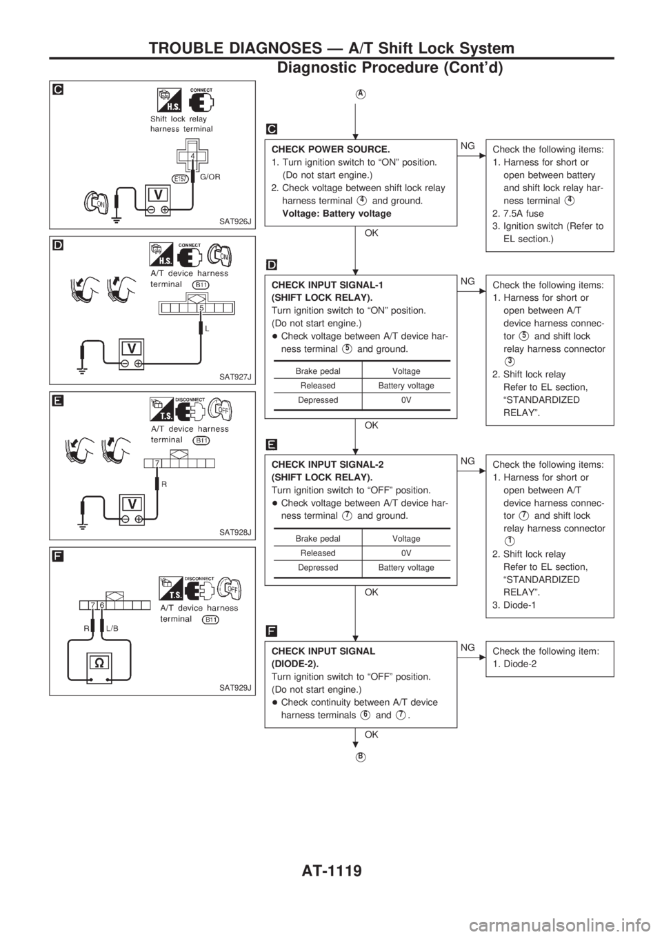
CHECK POWER SOURCE.
1. Turn ignition switch to ªONº position.
(Do not start engine.)
2. Check voltage between shift lock relay
harness terminal
V4and ground.
Voltage: Battery voltage
OK
cNG
Check the following items:
1. Harness for short or
open between battery
and shift lock relay har-
ness terminal
V4
2. 7.5A fuse
3. Ignition switch (Refer to
EL section.)
CHECK INPUT SIGNAL-1
(SHIFT LOCK RELAY).
Turn ignition switch to ªONº position.
(Do not start engine.)
+Check voltage between A/T device har-
ness terminal
V5and ground.
OK
cNG
Check the following items:
1. Harness for short or
open between A/T
device harness connec-
tor
V5and shift lock
relay harness connector
V3
2. Shift lock relay
Refer to EL section,
ªSTANDARDIZED
RELAYº.
CHECK INPUT SIGNAL-2
(SHIFT LOCK RELAY).
Turn ignition switch to ªOFFº position.
+Check voltage between A/T device har-
ness terminal
V7and ground.
OK
cNG
Check the following items:
1. Harness for short or
open between A/T
device harness connec-
tor
V7and shift lock
relay harness connector
V1
2. Shift lock relay
Refer to EL section,
ªSTANDARDIZED
RELAYº.
3. Diode-1
CHECK INPUT SIGNAL
(DIODE-2).
Turn ignition switch to ªOFFº position.
(Do not start engine.)
+Check continuity between A/T device
harness terminals
V6andV7.
OK
cNG
Check the following item:
1. Diode-2
VB
Brake pedal Voltage
Released Battery voltage
Depressed 0V
Brake pedal Voltage
Released 0V
Depressed Battery voltage
SAT926J
SAT927J
SAT928J
SAT929J
.
.
.
.
.
TROUBLE DIAGNOSES Ð A/T Shift Lock System
Diagnostic Procedure (Cont'd)
AT-1119
Page 158 of 1033
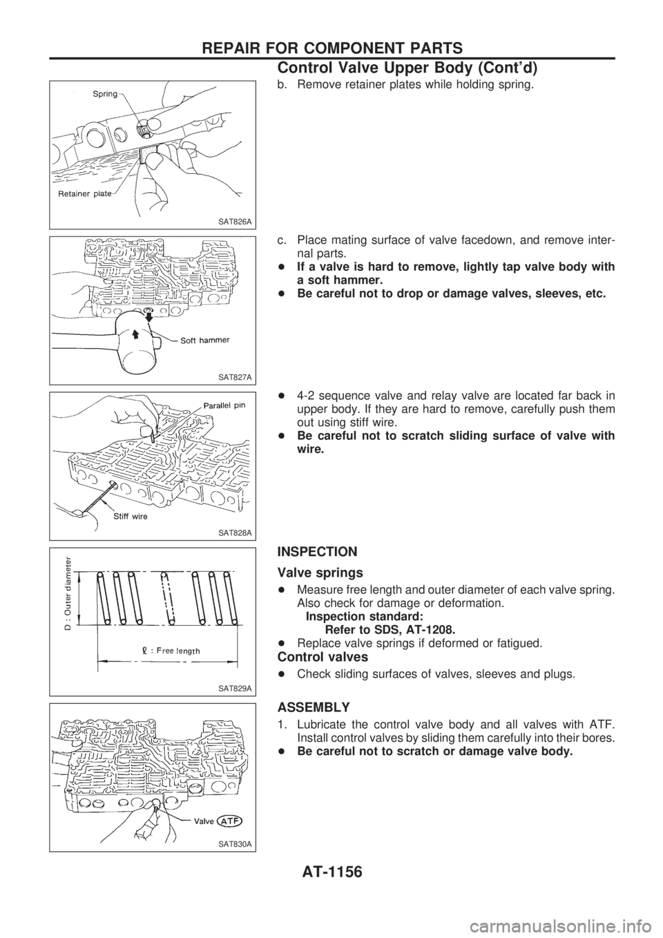
b. Remove retainer plates while holding spring.
c. Place mating surface of valve facedown, and remove inter-
nal parts.
+If a valve is hard to remove, lightly tap valve body with
a soft hammer.
+Be careful not to drop or damage valves, sleeves, etc.
+4-2 sequence valve and relay valve are located far back in
upper body. If they are hard to remove, carefully push them
out using stiff wire.
+Be careful not to scratch sliding surface of valve with
wire.
INSPECTION
Valve springs
+Measure free length and outer diameter of each valve spring.
Also check for damage or deformation.
Inspection standard:
Refer to SDS, AT-1208.
+Replace valve springs if deformed or fatigued.
Control valves
+Check sliding surfaces of valves, sleeves and plugs.
ASSEMBLY
1. Lubricate the control valve body and all valves with ATF.
Install control valves by sliding them carefully into their bores.
+Be careful not to scratch or damage valve body.
SAT826A
SAT827A
SAT828A
SAT829A
SAT830A
REPAIR FOR COMPONENT PARTS
Control Valve Upper Body (Cont'd)
AT-1156
Page 160 of 1033
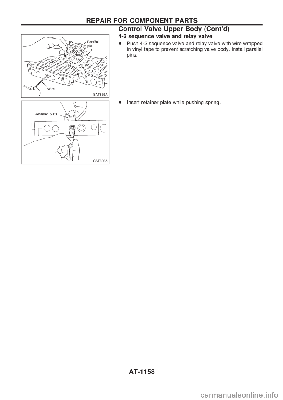
4-2 sequence valve and relay valve
+Push 4-2 sequence valve and relay valve with wire wrapped
in vinyl tape to prevent scratching valve body. Install parallel
pins.
+Insert retainer plate while pushing spring.
SAT835A
SAT836A
REPAIR FOR COMPONENT PARTS
Control Valve Upper Body (Cont'd)
AT-1158
Page 210 of 1033
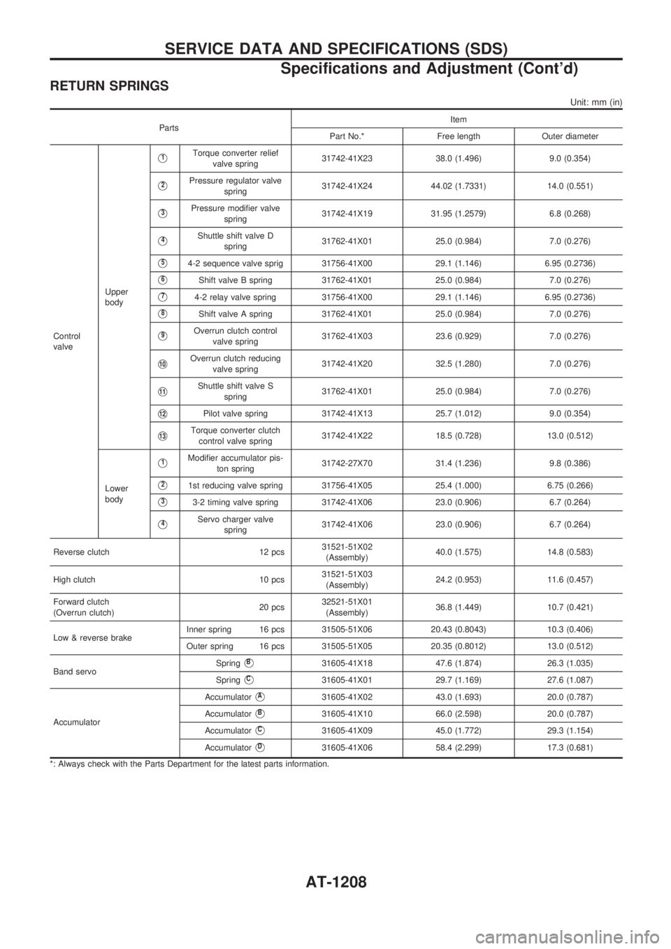
RETURN SPRINGS
Unit: mm (in)
PartsItem
Part No.* Free length Outer diameter
Control
valveUpper
body
V1Torque converter relief
valve spring31742-41X23 38.0 (1.496) 9.0 (0.354)
V2Pressure regulator valve
spring31742-41X24 44.02 (1.7331) 14.0 (0.551)
V3Pressure modifier valve
spring31742-41X19 31.95 (1.2579) 6.8 (0.268)
V4Shuttle shift valve D
spring31762-41X01 25.0 (0.984) 7.0 (0.276)
V54-2 sequence valve sprig 31756-41X00 29.1 (1.146) 6.95 (0.2736)
V6Shift valve B spring 31762-41X01 25.0 (0.984) 7.0 (0.276)
V74-2 relay valve spring 31756-41X00 29.1 (1.146) 6.95 (0.2736)
V8Shift valve A spring 31762-41X01 25.0 (0.984) 7.0 (0.276)
V9Overrun clutch control
valve spring31762-41X03 23.6 (0.929) 7.0 (0.276)
V10Overrun clutch reducing
valve spring31742-41X20 32.5 (1.280) 7.0 (0.276)
V11Shuttle shift valve S
spring31762-41X01 25.0 (0.984) 7.0 (0.276)
V12Pilot valve spring 31742-41X13 25.7 (1.012) 9.0 (0.354)
V13Torque converter clutch
control valve spring31742-41X22 18.5 (0.728) 13.0 (0.512)
Lower
body
V1Modifier accumulator pis-
ton spring31742-27X70 31.4 (1.236) 9.8 (0.386)
V21st reducing valve spring 31756-41X05 25.4 (1.000) 6.75 (0.266)
V33-2 timing valve spring 31742-41X06 23.0 (0.906) 6.7 (0.264)
V4Servo charger valve
spring31742-41X06 23.0 (0.906) 6.7 (0.264)
Reverse clutch 12 pcs31521-51X02
(Assembly)40.0 (1.575) 14.8 (0.583)
High clutch 10 pcs31521-51X03
(Assembly)24.2 (0.953) 11.6 (0.457)
Forward clutch
(Overrun clutch)20 pcs32521-51X01
(Assembly)36.8 (1.449) 10.7 (0.421)
Low & reverse brakeInner spring 16 pcs 31505-51X06 20.43 (0.8043) 10.3 (0.406)
Outer spring 16 pcs 31505-51X05 20.35 (0.8012) 13.0 (0.512)
Band servoSpring
VB31605-41X18 47.6 (1.874) 26.3 (1.035)
Spring
VC31605-41X01 29.7 (1.169) 27.6 (1.087)
AccumulatorAccumulator
VA31605-41X02 43.0 (1.693) 20.0 (0.787)
Accumulator
VB31605-41X10 66.0 (2.598) 20.0 (0.787)
Accumulator
VC31605-41X09 45.0 (1.772) 29.3 (1.154)
Accumulator
VD31605-41X06 58.4 (2.299) 17.3 (0.681)
*: Always check with the Parts Department for the latest parts information.
SERVICE DATA AND SPECIFICATIONS (SDS)
Specifications and Adjustment (Cont'd)
AT-1208
Page 251 of 1033
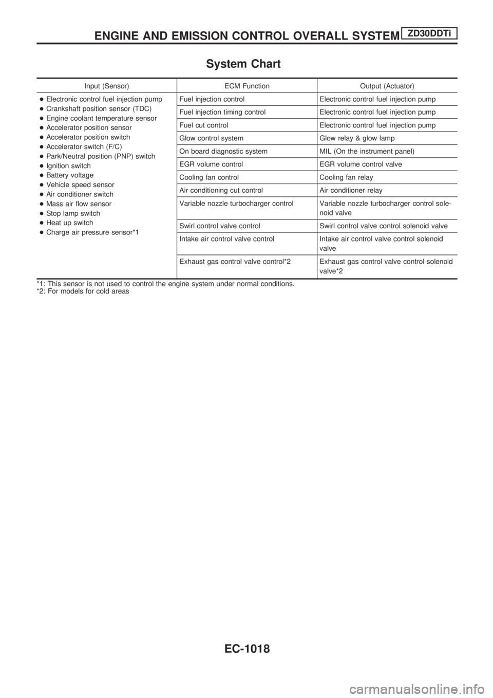
System Chart
Input (Sensor) ECM Function Output (Actuator)
+Electronic control fuel injection pump
+Crankshaft position sensor (TDC)
+Engine coolant temperature sensor
+Accelerator position sensor
+Accelerator position switch
+Accelerator switch (F/C)
+Park/Neutral position (PNP) switch
+Ignition switch
+Battery voltage
+Vehicle speed sensor
+Air conditioner switch
+Mass air flow sensor
+Stop lamp switch
+Heat up switch
+Charge air pressure sensor*1Fuel injection control Electronic control fuel injection pump
Fuel injection timing control Electronic control fuel injection pump
Fuel cut control Electronic control fuel injection pump
Glow control system Glow relay & glow lamp
On board diagnostic system MIL (On the instrument panel)
EGR volume control EGR volume control valve
Cooling fan control Cooling fan relay
Air conditioning cut control Air conditioner relay
Variable nozzle turbocharger control Variable nozzle turbocharger control sole-
noid valve
Swirl control valve control Swirl control valve control solenoid valve
Intake air control valve control Intake air control valve control solenoid
valve
Exhaust gas control valve control*2 Exhaust gas control valve control solenoid
valve*2
*1: This sensor is not used to control the engine system under normal conditions.
*2: For models for cold areas
ENGINE AND EMISSION CONTROL OVERALL SYSTEMZD30DDTi
EC-1018
Page 254 of 1033
Fuel Injection Timing Control System
DESCRIPTION
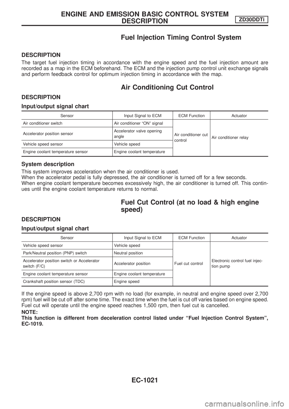
The target fuel injection timing in accordance with the engine speed and the fuel injection amount are
recorded as a map in the ECM beforehand. The ECM and the injection pump control unit exchange signals
and perform feedback control for optimum injection timing in accordance with the map.
Air Conditioning Cut Control
DESCRIPTION
Input/output signal chart
Sensor Input Signal to ECM ECM Function Actuator
Air conditioner switch Air conditioner ªONº signal
Air conditioner cut
controlAir conditioner relay Accelerator position sensorAccelerator valve opening
angle
Vehicle speed sensor Vehicle speed
Engine coolant temperature sensor Engine coolant temperature
System description
This system improves acceleration when the air conditioner is used.
When the accelerator pedal is fully depressed, the air conditioner is turned off for a few seconds.
When engine coolant temperature becomes excessively high, the air conditioner is turned off. This contin-
ues until the engine coolant temperature returns to normal.
Fuel Cut Control (at no load & high engine
speed)
DESCRIPTION
Input/output signal chart
Sensor Input Signal to ECM ECM Function Actuator
Vehicle speed sensor Vehicle speed
Fuel cut controlElectronic control fuel injec-
tion pump Park/Neutral position (PNP) switch Neutral position
Accelerator position switch or Accelerator
switch (F/C)Accelerator position
Engine coolant temperature sensor Engine coolant temperature
Crankshaft position sensor (TDC) Engine speed
If the engine speed is above 2,700 rpm with no load (for example, in neutral and engine speed over 2,700
rpm) fuel will be cut off after some time. The exact time when the fuel is cut off varies based on engine speed.
Fuel cut will operate until the engine speed reaches 1,500 rpm, then fuel cut is cancelled.
NOTE:
This function is different from deceleration control listed under ªFuel Injection Control Systemº,
EC-1019.
ENGINE AND EMISSION BASIC CONTROL SYSTEM
DESCRIPTIONZD30DDTi
EC-1021
Page 272 of 1033
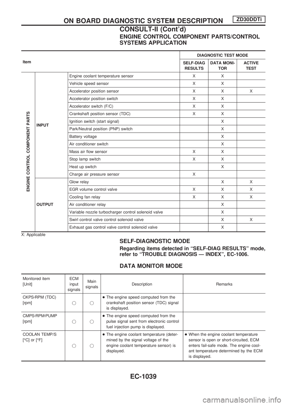
ENGINE CONTROL COMPONENT PARTS/CONTROL
SYSTEMS APPLICATION
ItemDIAGNOSTIC TEST MODE
SELF-DIAG
RESULTSDATA MONI-
TORACTIVE
TEST
ENGINE CONTROL COMPONENT PARTS
INPUTEngine coolant temperature sensor X X
Vehicle speed sensor X X
Accelerator position sensor X X X
Accelerator position switch X X
Accelerator switch (F/C) X X
Crankshaft position sensor (TDC) X X
Ignition switch (start signal) X
Park/Neutral position (PNP) switch X
Battery voltage X
Air conditioner switch X
Mass air flow sensor X X
Stop lamp switch X X
Heat up switch X
Charge air pressure sensor X
OUTPUTGlow relayXX
EGR volume control valve X X X
Cooling fan relay X X X
Air conditioner relay X
Variable nozzle turbocharger control solenoid valve X
Swirl control valve control solenoid valve X X
Exhaust gas control valve control solenoid valve X
X: Applicable
SELF-DIAGNOSTIC MODE
Regarding items detected in ªSELF-DIAG RESULTSº mode,
refer to ªTROUBLE DIAGNOSIS Ð INDEXº, EC-1006.
DATA MONITOR MODE
Monitored item
[Unit]ECM
input
signalsMain
signalsDescription Remarks
CKPSzRPM (TDC)
[rpm]jj+The engine speed computed from the
crankshaft position sensor (TDC) signal
is displayed.
CMPSzRPMzPUMP
[rpm]jj+The engine speed computed from the
pulse signal sent from electronic control
fuel injection pump is displayed.
COOLAN TEMP/S
[ÉC] or [ÉF]
jj+The engine coolant temperature (deter-
mined by the signal voltage of the
engine coolant temperature sensor) is
displayed.+When the engine coolant temperature
sensor is open or short-circuited, ECM
enters fail-safe mode. The engine cool-
ant temperature determined by the ECM
is displayed.
ON BOARD DIAGNOSTIC SYSTEM DESCRIPTIONZD30DDTi
CONSULT-II (Cont'd)
EC-1039