2000 NISSAN PATROL wheel alignment
[x] Cancel search: wheel alignmentPage 901 of 1033
![NISSAN PATROL 2000 Electronic Repair Manual Chassis and Body Maintenance
Abbreviations: R = Replace, I = Inspect: Correct or replace if necessary, L = Lubricate, T = Tighten, [ ] = At the specified mileage only
MAINTENANCE OPERATIONMAINTENANCE NISSAN PATROL 2000 Electronic Repair Manual Chassis and Body Maintenance
Abbreviations: R = Replace, I = Inspect: Correct or replace if necessary, L = Lubricate, T = Tighten, [ ] = At the specified mileage only
MAINTENANCE OPERATIONMAINTENANCE](/manual-img/5/57367/w960_57367-900.png)
Chassis and Body Maintenance
Abbreviations: R = Replace, I = Inspect: Correct or replace if necessary, L = Lubricate, T = Tighten, [ ] = At the specified mileage only
MAINTENANCE OPERATIONMAINTENANCE INTERVAL
Perform on a kilometer basis, but on an annual basis
when driving less than 15,000 km (9,000 miles) per
year.km x 1,000 15 30 45 60 75 90
(miles x 1,000) (9) (18) (27) (36) (45) (54)
Months 12 24 36 48 60 72
Underhood and under vehicleReference
pages
Headlamp aimingIIIIII Ð
When alignment (if necessary, balance & rotate wheels)IIIIII Ð
Brake pads, rotors & other brake componentsHIIIIII Ð
Foot brake, parking brake & clutch (for free play, stroke & operation)IIIIII Ð
Brake booster vacuum hoses, connections & check valve I I I Ð
Brake & clutch, systems and fluid (for level and leaks)IIIIII Ð
Brake fluidHRRRÐ
Power steering fluid and lines (for level and leaks)IIIIII Ð
Supplemental air bag systems See NOTE (1)RS-1007
Ventilation air filterHRRRÐ
Manual transmission oil (Inspect for leaks. Replace if leaks are found.)IIIII[R] Ð
Automatic transmission fluid (for level and leaks)HIIIIII Ð
Greasing point of propeller shaft See NOTE (2)LLLLLL Ð
Transfer fluid and limited-slip differential (LSD) gear oil (for
level & leaks or replace)HSee NOTE (3) I I I R I I Ð
Drive shafts & steering damperHIIIIII Ð
Front wheel bearing greaseHIRIRIR Ð
Front axle joint in knuckle flangeLLLÐ
Free-running hub greaseHIIIIII Ð
Body mounting bolts & nutsTTTTTT Ð
Steering gear & linkage, axle & suspension parts, propeller shaft & exhaust systemHIIIIII Ð
Body corrosion See NOTE (4)Ð
NOTE: (1) Inspect after 10 years, then every 2 years.
(2) The propeller shaft should be re-greased after being immersed in water.
(3) Including differential gear with differential lock.
(4) Inspect once per year.
HMaintenance items with ªHº should be performed more frequently according to ªMaintenance under severe driv-
ing conditionsº.
PERIODIC MAINTENANCE
MA-1003
Page 904 of 1033

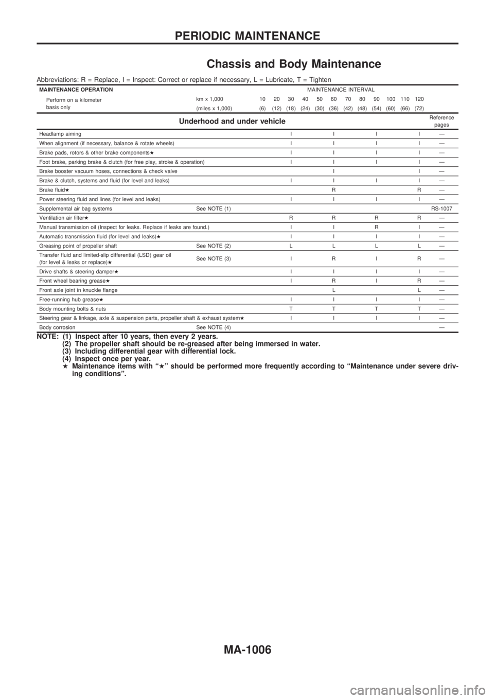
Chassis and Body Maintenance
Abbreviations: R = Replace, I = Inspect: Correct or replace if necessary, L = Lubricate, T = Tighten
MAINTENANCE OPERATIONMAINTENANCE INTERVAL
Perform on a kilometer
basis onlykm x 1,000 10 20 30 40 50 60 70 80 90 100 110 120
(miles x 1,000) (6) (12) (18) (24) (30) (36) (42) (48) (54) (60) (66) (72)
Underhood and under vehicleReference
pages
Headlamp aimingIIIIÐ
When alignment (if necessary, balance & rotate wheels)IIIIÐ
Brake pads, rotors & other brake componentsHIIIIÐ
Foot brake, parking brake & clutch (for free play, stroke & operation)IIIIÐ
Brake booster vacuum hoses, connections & check valve I I Ð
Brake & clutch, systems and fluid (for level and leaks)IIIIÐ
Brake fluidHRRÐ
Power steering fluid and lines (for level and leaks)IIIIÐ
Supplemental air bag systems See NOTE (1)RS-1007
Ventilation air filterHRRRRÐ
Manual transmission oil (Inspect for leaks. Replace if leaks are found.) I I R I Ð
Automatic transmission fluid (for level and leaks)HIIIIÐ
Greasing point of propeller shaft See NOTE (2)LLLLÐ
Transfer fluid and limited-slip differential (LSD) gear oil
(for level & leaks or replace)HSee NOTE (3) I R I R Ð
Drive shafts & steering damperHIIIIÐ
Front wheel bearing greaseHIRIRÐ
Front axle joint in knuckle flangeLLÐ
Free-running hub greaseHIIIIÐ
Body mounting bolts & nutsTTTTÐ
Steering gear & linkage, axle & suspension parts, propeller shaft & exhaust systemHIIIIÐ
Body corrosion See NOTE (4)Ð
NOTE: (1) Inspect after 10 years, then every 2 years.
(2) The propeller shaft should be re-greased after being immersed in water.
(3) Including differential gear with differential lock.
(4) Inspect once per year.
HMaintenance items with ªHº should be performed more frequently according to ªMaintenance under severe driv-
ing conditionsº.
PERIODIC MAINTENANCE
MA-1006
Page 978 of 1033

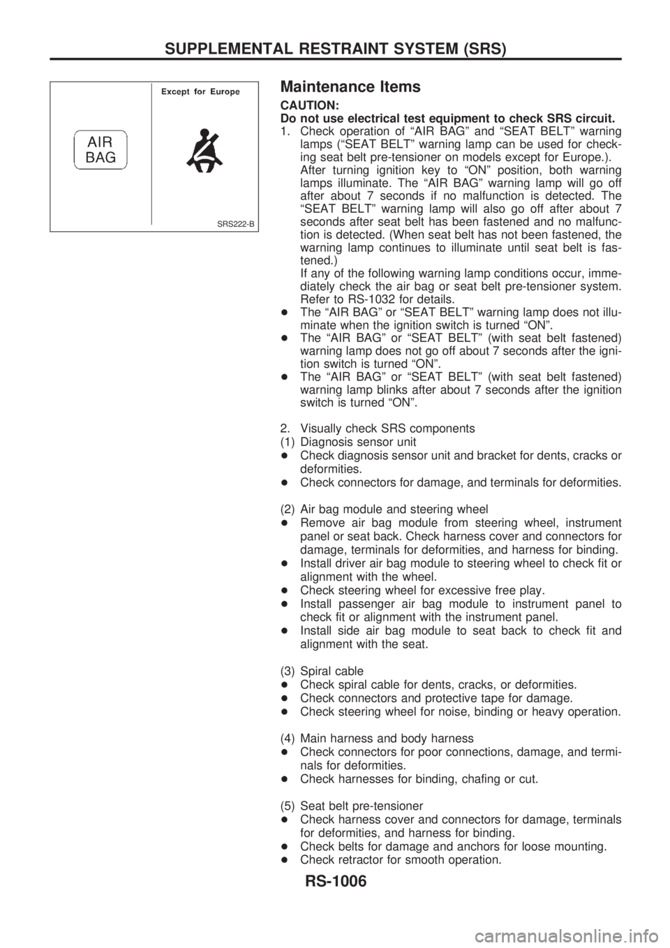
Maintenance Items
CAUTION:
Do not use electrical test equipment to check SRS circuit.
1. Check operation of ªAIR BAGº and ªSEAT BELTº warning
lamps (ªSEAT BELTº warning lamp can be used for check-
ing seat belt pre-tensioner on models except for Europe.).
After turning ignition key to ªONº position, both warning
lamps illuminate. The ªAIR BAGº warning lamp will go off
after about 7 seconds if no malfunction is detected. The
ªSEAT BELTº warning lamp will also go off after about 7
seconds after seat belt has been fastened and no malfunc-
tion is detected. (When seat belt has not been fastened, the
warning lamp continues to illuminate until seat belt is fas-
tened.)
If any of the following warning lamp conditions occur, imme-
diately check the air bag or seat belt pre-tensioner system.
Refer to RS-1032 for details.
+The ªAIR BAGº or ªSEAT BELTº warning lamp does not illu-
minate when the ignition switch is turned ªONº.
+The ªAIR BAGº or ªSEAT BELTº (with seat belt fastened)
warning lamp does not go off about 7 seconds after the igni-
tion switch is turned ªONº.
+The ªAIR BAGº or ªSEAT BELTº (with seat belt fastened)
warning lamp blinks after about 7 seconds after the ignition
switch is turned ªONº.
2. Visually check SRS components
(1) Diagnosis sensor unit
+Check diagnosis sensor unit and bracket for dents, cracks or
deformities.
+Check connectors for damage, and terminals for deformities.
(2) Air bag module and steering wheel
+Remove air bag module from steering wheel, instrument
panel or seat back. Check harness cover and connectors for
damage, terminals for deformities, and harness for binding.
+Install driver air bag module to steering wheel to check fit or
alignment with the wheel.
+Check steering wheel for excessive free play.
+Install passenger air bag module to instrument panel to
check fit or alignment with the instrument panel.
+Install side air bag module to seat back to check fit and
alignment with the seat.
(3) Spiral cable
+Check spiral cable for dents, cracks, or deformities.
+Check connectors and protective tape for damage.
+Check steering wheel for noise, binding or heavy operation.
(4) Main harness and body harness
+Check connectors for poor connections, damage, and termi-
nals for deformities.
+Check harnesses for binding, chafing or cut.
(5) Seat belt pre-tensioner
+Check harness cover and connectors for damage, terminals
for deformities, and harness for binding.
+Check belts for damage and anchors for loose mounting.
+Check retractor for smooth operation.
SRS222-B
SUPPLEMENTAL RESTRAINT SYSTEM (SRS)
RS-1006
Page 1024 of 1033

FOR FRONTAL COLLISION
To repair the SRS for a frontal collision, perform the following steps.
When SRS (except the side air bag) is activated in a collision:
V1Replace the diagnosis sensor unit.
V2Remove the air bag modules (except the side air bag module) and seat belt pre-tensioner assemblies.
V3Check the SRS components using the table shown below:
+Replace any SRS components showing visible signs of damage (dents, cracks, deformation).
V4Install new air bag modules (except the side air bag module) and seat belt pre-tensioner assemblies.
V5Conduct self-diagnosis using CONSULT-II, and ªAIR BAGº and ªSEAT BELTº warning lamps (Models
except for Europe). Refer to ªSelf-diagnosisº for details (RS-1032). Ensure entire SRS operates prop-
erly.
When SRS is not activated in a collision:
V1Check the SRS components using the table shown below:
+Replace any SRS components showing visible signs of damage (dents, cracks, deformation).
V2Conduct self-diagnosis using CONSULT-II, and ªAIR BAGº and ªSEAT BELTº warning lamps (Models
except for Europe). Refer to ªSelf-diagnosisº for details (RS-1032). Ensure entire SRS operates prop-
erly.
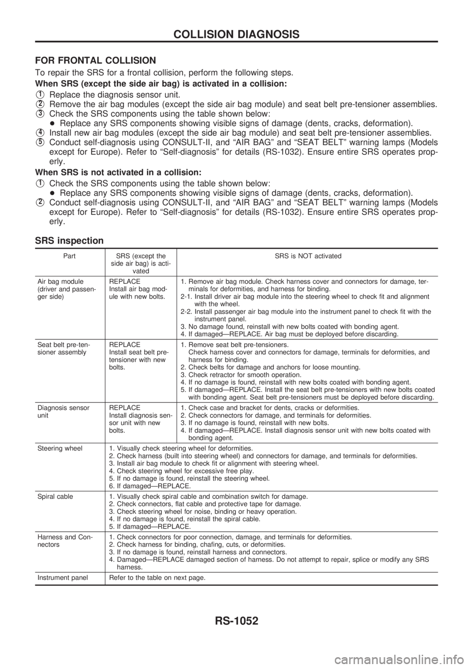
SRS inspection
Part SRS (except the
side air bag) is acti-
vatedSRS is NOT activated
Air bag module
(driver and passen-
ger side)REPLACE
Install air bag mod-
ule with new bolts.1. Remove air bag module. Check harness cover and connectors for damage, ter-
minals for deformities, and harness for binding.
2-1. Install driver air bag module into the steering wheel to check fit and alignment
with the wheel.
2-2. Install passenger air bag module into the instrument panel to check fit with the
instrument panel.
3. No damage found, reinstall with new bolts coated with bonding agent.
4. If damagedÐREPLACE. Air bag must be deployed before discarding.
Seat belt pre-ten-
sioner assemblyREPLACE
Install seat belt pre-
tensioner with new
bolts.1. Remove seat belt pre-tensioners.
Check harness cover and connectors for damage, terminals for deformities, and
harness for binding.
2. Check belts for damage and anchors for loose mounting.
3. Check retractor for smooth operation.
4. If no damage is found, reinstall with new bolts coated with bonding agent.
5. If damagedÐREPLACE. Install the seat belt pre-tensioners with new bolts coated
with bonding agent. Seat belt pre-tensioners must be deployed before discarding.
Diagnosis sensor
unitREPLACE
Install diagnosis sen-
sor unit with new
bolts.1. Check case and bracket for dents, cracks or deformities.
2. Check connectors for damage, and terminals for deformities.
3. If no damage is found, reinstall with new bolts.
4. If damagedÐREPLACE. Install diagnosis sensor unit with new bolts coated with
bonding agent.
Steering wheel 1. Visually check steering wheel for deformities.
2. Check harness (built into steering wheel) and connectors for damage, and terminals for deformities.
3. Install air bag module to check fit or alignment with steering wheel.
4. Check steering wheel for excessive free play.
5. If no damage is found, reinstall the steering wheel.
6. If damagedÐREPLACE.
Spiral cable 1. Visually check spiral cable and combination switch for damage.
2. Check connectors, flat cable and protective tape for damage.
3. Check steering wheel for noise, binding or heavy operation.
4. If no damage is found, reinstall the spiral cable.
5. If damagedÐREPLACE.
Harness and Con-
nectors1. Check connectors for poor connection, damage, and terminals for deformities.
2. Check harness for binding, chafing, cuts, or deformities.
3. If no damage is found, reinstall harness and connectors.
4. DamagedÐREPLACE damaged section of harness. Do not attempt to repair, splice or modify any SRS
harness.
Instrument panel Refer to the table on next page.
COLLISION DIAGNOSIS
RS-1052