2000 NISSAN PATROL relay
[x] Cancel search: relayPage 616 of 1033
Trouble Diagnoses
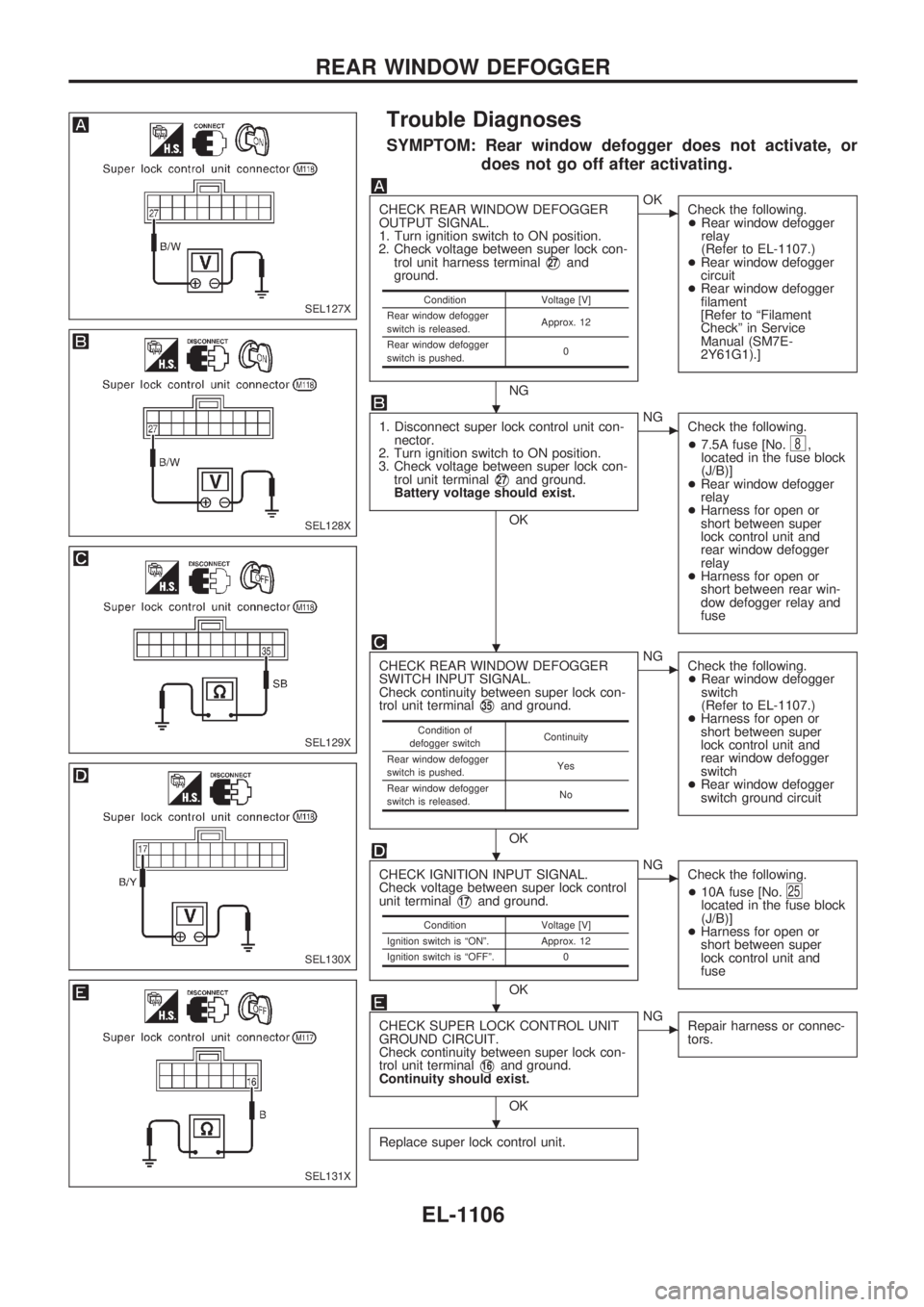
SYMPTOM: Rear window defogger does not activate, or
does not go off after activating.
CHECK REAR WINDOW DEFOGGER
OUTPUT SIGNAL.
1. Turn ignition switch to ON position.
2. Check voltage between super lock con-
trol unit harness terminal
V27and
ground.
NG
cOK
Check the following.
+Rear window defogger
relay
(Refer to EL-1107.)
+Rear window defogger
circuit
+Rear window defogger
filament
[Refer to ªFilament
Checkº in Service
Manual (SM7E-
2Y61G1).]
1. Disconnect super lock control unit con-
nector.
2. Turn ignition switch to ON position.
3. Check voltage between super lock con-
trol unit terminal
V27and ground.
Battery voltage should exist.
OK
cNG
Check the following.
+7.5A fuse [No.
8,
located in the fuse block
(J/B)]
+Rear window defogger
relay
+Harness for open or
short between super
lock control unit and
rear window defogger
relay
+Harness for open or
short between rear win-
dow defogger relay and
fuse
CHECK REAR WINDOW DEFOGGER
SWITCH INPUT SIGNAL.
Check continuity between super lock con-
trol unit terminal
V35and ground.
OK
cNG
Check the following.
+Rear window defogger
switch
(Refer to EL-1107.)
+Harness for open or
short between super
lock control unit and
rear window defogger
switch
+Rear window defogger
switch ground circuit
CHECK IGNITION INPUT SIGNAL.
Check voltage between super lock control
unit terminal
V17and ground.
OK
cNG
Check the following.
+10A fuse [No.
25located in the fuse block
(J/B)]
+Harness for open or
short between super
lock control unit and
fuse
CHECK SUPER LOCK CONTROL UNIT
GROUND CIRCUIT.
Check continuity between super lock con-
trol unit terminal
V16and ground.
Continuity should exist.
OK
cNG
Repair harness or connec-
tors.
Replace super lock control unit.
Condition Voltage [V]
Rear window defogger
switch is released.Approx. 12
Rear window defogger
switch is pushed.0
Condition of
defogger switchContinuity
Rear window defogger
switch is pushed.Yes
Rear window defogger
switch is released.No
Condition Voltage [V]
Ignition switch is ªONº. Approx. 12
Ignition switch is ªOFFº. 0
SEL127X
SEL128X
SEL129X
SEL130X
SEL131X
.
.
.
.
.
REAR WINDOW DEFOGGER
EL-1106
Page 617 of 1033
Electrical Components Inspection
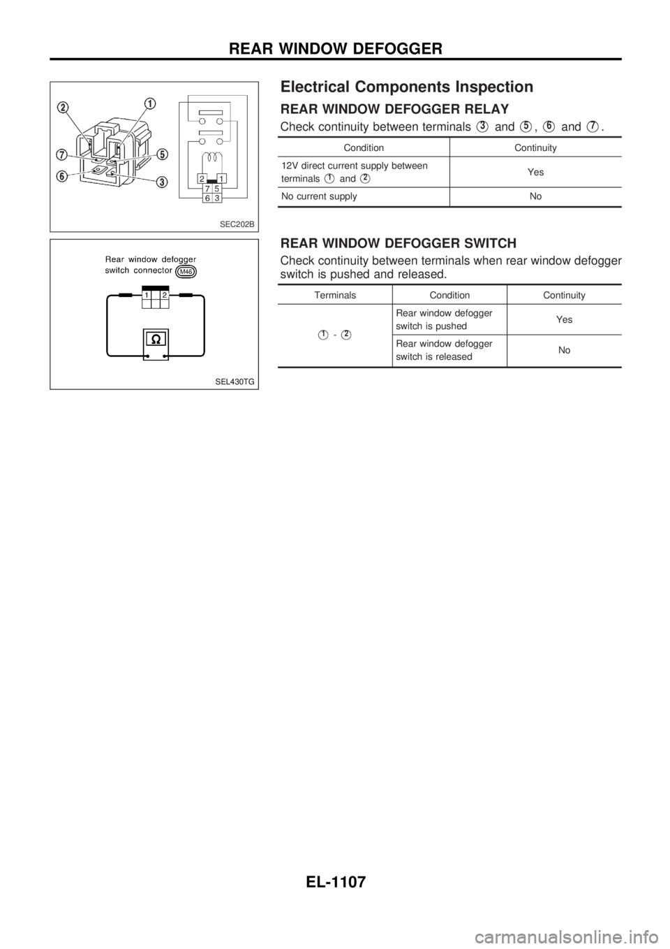
REAR WINDOW DEFOGGER RELAY
Check continuity between terminalsV3andV5,V6andV7.
Condition Continuity
12V direct current supply between
terminals
V1andV2Yes
No current supply No
REAR WINDOW DEFOGGER SWITCH
Check continuity between terminals when rear window defogger
switch is pushed and released.
Terminals Condition Continuity
V1-V2
Rear window defogger
switch is pushedYes
Rear window defogger
switch is releasedNo
SEC202B
SEL430TG
REAR WINDOW DEFOGGER
EL-1107
Page 632 of 1033
Trouble Diagnoses
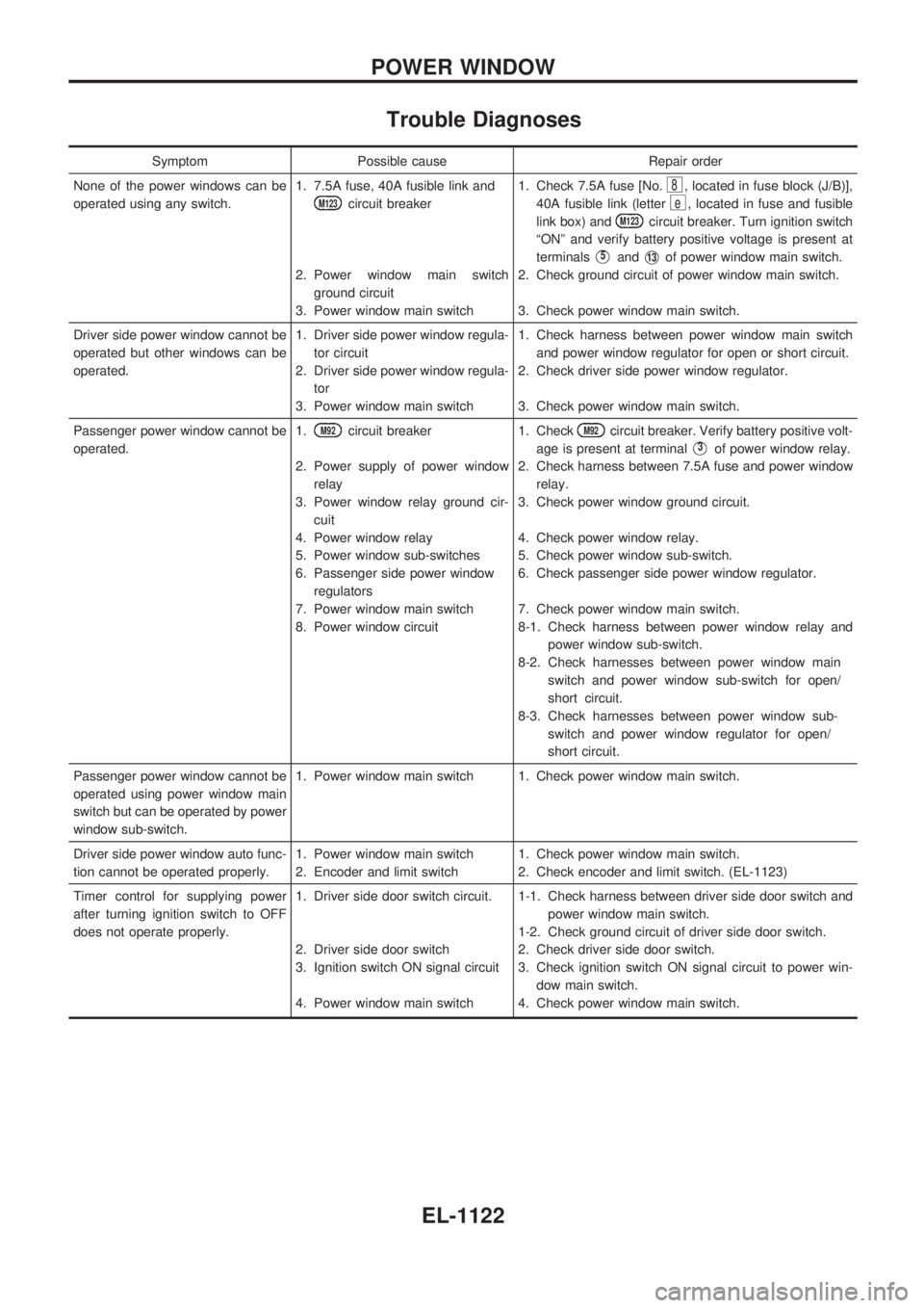
Symptom Possible cause Repair order
None of the power windows can be
operated using any switch.1. 7.5A fuse, 40A fusible link and
M123circuit breaker
2. Power window main switch
ground circuit
3. Power window main switch1. Check 7.5A fuse [No.
8, located in fuse block (J/B)],
40A fusible link (letter
e, located in fuse and fusible
link box) and
M123circuit breaker. Turn ignition switch
ªONº and verify battery positive voltage is present at
terminals
V5andV13of power window main switch.
2. Check ground circuit of power window main switch.
3. Check power window main switch.
Driver side power window cannot be
operated but other windows can be
operated.1. Driver side power window regula-
tor circuit
2. Driver side power window regula-
tor
3. Power window main switch1. Check harness between power window main switch
and power window regulator for open or short circuit.
2. Check driver side power window regulator.
3. Check power window main switch.
Passenger power window cannot be
operated.1.
M92circuit breaker
2. Power supply of power window
relay
3. Power window relay ground cir-
cuit
4. Power window relay
5. Power window sub-switches
6. Passenger side power window
regulators
7. Power window main switch
8. Power window circuit1. CheckM92circuit breaker. Verify battery positive volt-
age is present at terminal
V3of power window relay.
2. Check harness between 7.5A fuse and power window
relay.
3. Check power window ground circuit.
4. Check power window relay.
5. Check power window sub-switch.
6. Check passenger side power window regulator.
7. Check power window main switch.
8-1. Check harness between power window relay and
power window sub-switch.
8-2. Check harnesses between power window main
switch and power window sub-switch for open/
short circuit.
8-3. Check harnesses between power window sub-
switch and power window regulator for open/
short circuit.
Passenger power window cannot be
operated using power window main
switch but can be operated by power
window sub-switch.1. Power window main switch 1. Check power window main switch.
Driver side power window auto func-
tion cannot be operated properly.1. Power window main switch
2. Encoder and limit switch1. Check power window main switch.
2. Check encoder and limit switch. (EL-1123)
Timer control for supplying power
after turning ignition switch to OFF
does not operate properly.1. Driver side door switch circuit.
2. Driver side door switch
3. Ignition switch ON signal circuit
4. Power window main switch1-1. Check harness between driver side door switch and
power window main switch.
1-2. Check ground circuit of driver side door switch.
2. Check driver side door switch.
3. Check ignition switch ON signal circuit to power win-
dow main switch.
4. Check power window main switch.
POWER WINDOW
EL-1122
Page 669 of 1033
Description
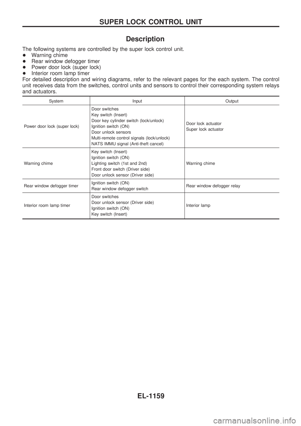
The following systems are controlled by the super lock control unit.
+Warning chime
+Rear window defogger timer
+Power door lock (super lock)
+Interior room lamp timer
For detailed description and wiring diagrams, refer to the relevant pages for the each system. The control
unit receives data from the switches, control units and sensors to control their corresponding system relays
and actuators.
System Input Output
Power door lock (super lock)Door switches
Key switch (Insert)
Door key cylinder switch (lock/unlock)
Ignition switch (ON)
Door unlock sensors
Multi-remote control signals (lock/unlock)
NATS IMMU signal (Anti-theft cancel)Door lock actuator
Super lock actuator
Warning chimeKey switch (Insert)
Ignition switch (ON)
Lighting switch (1st and 2nd)
Front door switch (Driver side)
Door unlock sensor (Driver side)Warning chime
Rear window defogger timerIgnition switch (ON)
Rear window defogger switchRear window defogger relay
Interior room lamp timerDoor switches
Door unlock sensor (Driver side)
Ignition switch (ON)
Key switch (Insert)Interior lamp
SUPER LOCK CONTROL UNIT
EL-1159
Page 672 of 1033
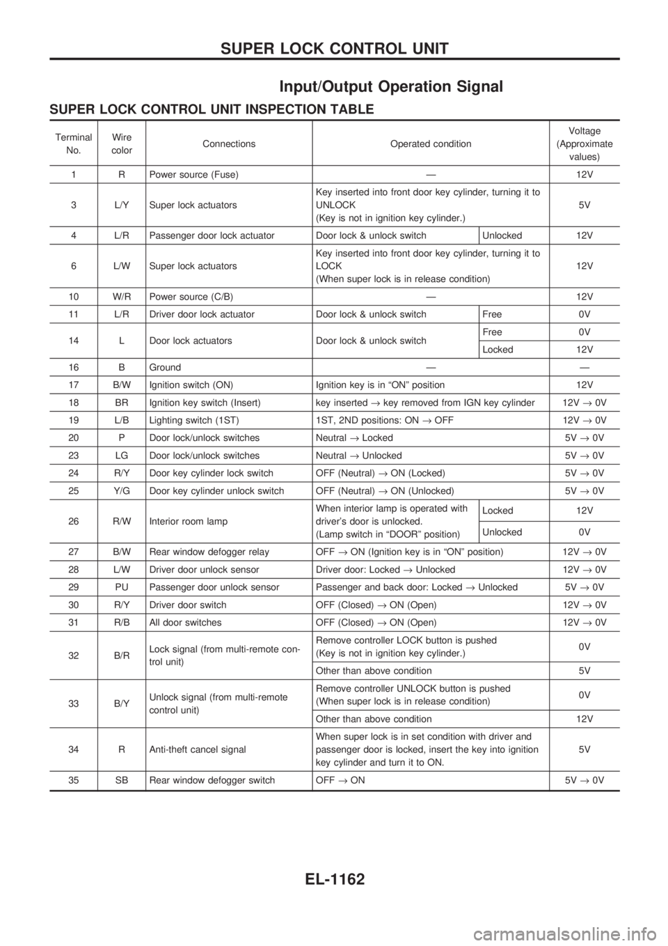
Input/Output Operation Signal
SUPER LOCK CONTROL UNIT INSPECTION TABLE
Terminal
No.Wire
colorConnections Operated conditionVoltage
(Approximate
values)
1 R Power source (Fuse) Ð 12V
3 L/Y Super lock actuatorsKey inserted into front door key cylinder, turning it to
UNLOCK
(Key is not in ignition key cylinder.)5V
4 L/R Passenger door lock actuator Door lock & unlock switch Unlocked 12V
6 L/W Super lock actuatorsKey inserted into front door key cylinder, turning it to
LOCK
(When super lock is in release condition)12V
10 W/R Power source (C/B) Ð 12V
11 L/R Driver door lock actuator Door lock & unlock switch Free 0V
14 L Door lock actuators Door lock & unlock switchFree 0V
Locked 12V
16 B Ground Ð Ð
17 B/W Ignition switch (ON) Ignition key is in ªONº position 12V
18 BR Ignition key switch (Insert) key inserted®key removed from IGN key cylinder 12V®0V
19 L/B Lighting switch (1ST) 1ST, 2ND positions: ON®OFF 12V®0V
20 P Door lock/unlock switches Neutral®Locked 5V®0V
23 LG Door lock/unlock switches Neutral®Unlocked 5V®0V
24 R/Y Door key cylinder lock switch OFF (Neutral)®ON (Locked) 5V®0V
25 Y/G Door key cylinder unlock switch OFF (Neutral)®ON (Unlocked) 5V®0V
26 R/W Interior room lampWhen interior lamp is operated with
driver's door is unlocked.
(Lamp switch in ªDOORº position)Locked 12V
Unlocked 0V
27 B/W Rear window defogger relay OFF®ON (Ignition key is in ªONº position) 12V®0V
28 L/W Driver door unlock sensor Driver door: Locked®Unlocked 12V®0V
29 PU Passenger door unlock sensor Passenger and back door: Locked®Unlocked 5V®0V
30 R/Y Driver door switch OFF (Closed)®ON (Open) 12V®0V
31 R/B All door switches OFF (Closed)®ON (Open) 12V®0V
32 B/RLock signal (from multi-remote con-
trol unit)Remove controller LOCK button is pushed
(Key is not in ignition key cylinder.)0V
Other than above condition 5V
33 B/YUnlock signal (from multi-remote
control unit)Remove controller UNLOCK button is pushed
(When super lock is in release condition)0V
Other than above condition 12V
34 R Anti-theft cancel signalWhen super lock is in set condition with driver and
passenger door is locked, insert the key into ignition
key cylinder and turn it to ON.5V
35 SB Rear window defogger switch OFF®ON 5V®0V
SUPER LOCK CONTROL UNIT
EL-1162
Page 701 of 1033
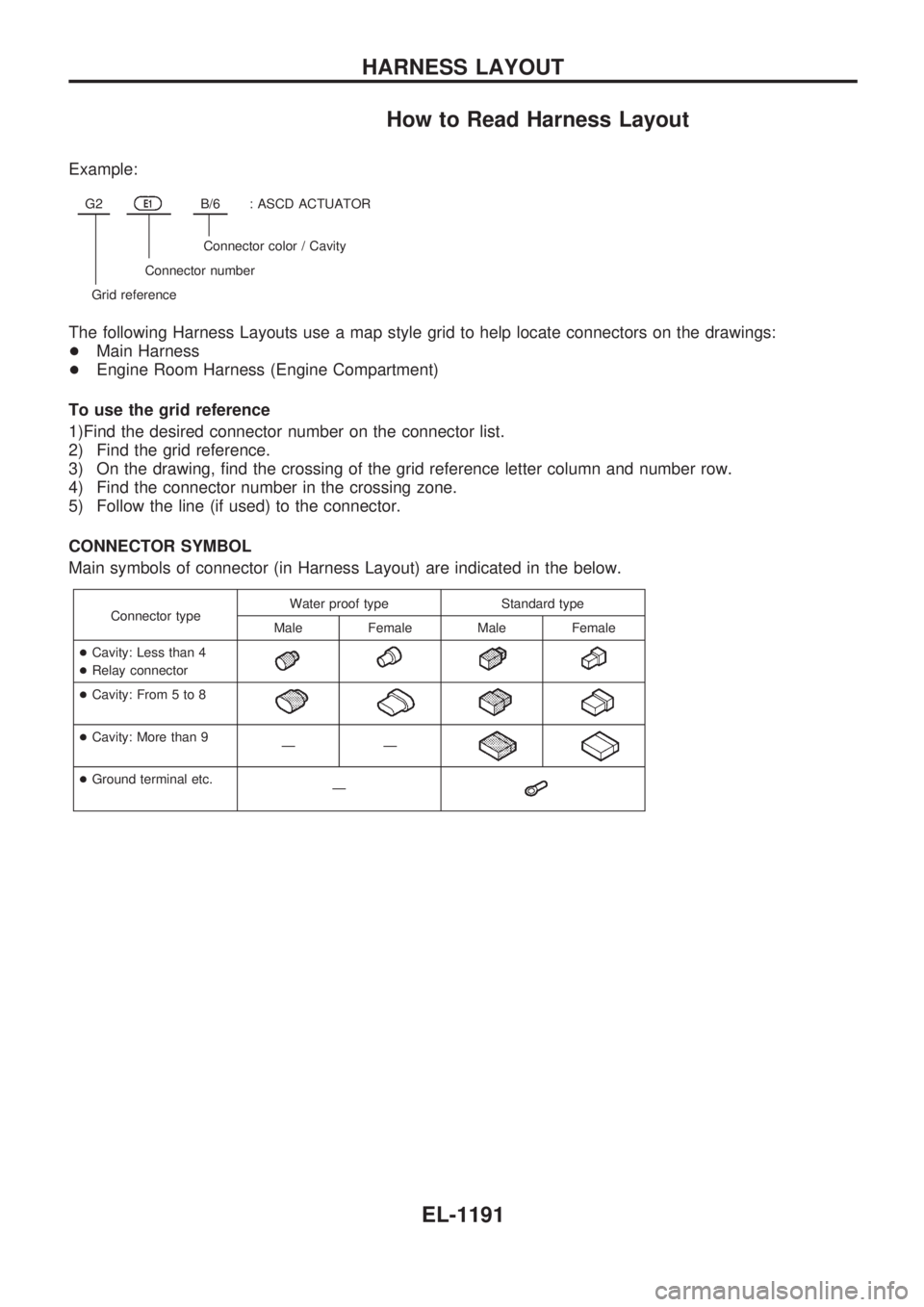
How to Read Harness Layout
Example:
G2E1B/6: ASCD ACTUATOR
Connector color / Cavity
Connector number
Grid reference
The following Harness Layouts use a map style grid to help locate connectors on the drawings:
+Main Harness
+Engine Room Harness (Engine Compartment)
To use the grid reference
1)Find the desired connector number on the connector list.
2) Find the grid reference.
3) On the drawing, find the crossing of the grid reference letter column and number row.
4) Find the connector number in the crossing zone.
5) Follow the line (if used) to the connector.
CONNECTOR SYMBOL
Main symbols of connector (in Harness Layout) are indicated in the below.
Connector typeWater proof type Standard type
Male Female Male Female
+Cavity: Less than 4
+Relay connector
+Cavity: From 5 to 8
+Cavity: More than 9
ÐÐ
+Ground terminal etc.
Ð
HARNESS LAYOUT
EL-1191
Page 737 of 1033
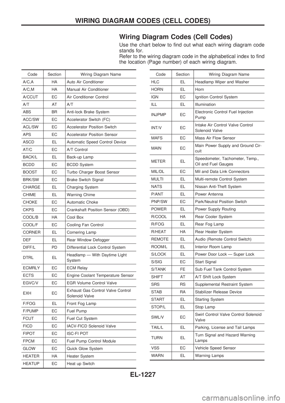
Wiring Diagram Codes (Cell Codes)
Use the chart below to find out what each wiring diagram code
stands for.
Refer to the wiring diagram code in the alphabetical index to find
the location (Page number) of each wiring diagram.
Code Section Wiring Diagram Name
A/C,A HA Auto Air Conditioner
A/C,M HA Manual Air Conditioner
A/CCUT EC Air Conditioner Control
A/T AT A/T
ABS BR Anti-lock Brake System
ACC/SW EC Accelerator Switch (FC)
ACL/SW EC Accelerator Position Switch
APS EC Accelerator Position Sensor
ASCD EL Automatic Speed Control Device
AT/C EC A/T Control
BACK/L EL Back-up Lamp
BCDD EC BCDD System
BOOST EC Turbo Charger Boost Sensor
BRK/SW EC Brake Switch Signal
CHARGE EL Charging System
CHIME EL Warning Chime
CHOKE EC Automatic Choke
CKPS EC Crankshaft Position Sensor (OBD)
COOL/B HA Cool Box
COOL/F EC Cooling Fan Control
CORNER EL Cornering Lamp
DEF EL Rear Window Defogger
DIFF/L PD Differential Lock Control System
DTRL ELHeadlamp Ð With Daytime Light
System
ECMRLY EC ECM Relay
ECTS EC Engine Coolant Temperature Sensor
EGVC/V EC EGR Volume Control Valve
EXH ECExhaust Gas Control Valve Control
Solenoid Valve
F/FOG EL Front Fog Lamp
F/PUMP EC Fuel Pump
FCUT EC Fuel Cut System
FICD EC IACV-FICD Solenoid Valve
FIPOT EC ISC-FI POT
FPCM EC Fuel Pump Control Module
GLOW EC Quick Glow System
HEATER HA Heater System
HEATUP EC Heat up SwitchCode Section Wiring Diagram Name
HLC EL Headlamp Wiper and Washer
HORN EL Horn
IGN EC Ignition Control System
ILL EL Illumination
INJPMP ECElectronic Control Fuel Injection
Pump
INT/V ECIntake Air Control Valve Control
Solenoid Valve
MAFS EC Mass Air Flow Sensor
MAIN ECMain Power Supply and Ground Cir-
cuit
METER ELSpeedometer, Tachometer, Temp.,
Oil and Fuel Gauges
MIL/DL EC Mil and Data Link Connectors
MULTI EL Multi-remote Control System
NATS EL Nissan Anti-Theft System
P/ANT EL Power Antenna
PNP/SW EC Park/Neutral Position Switch
POWER EL Power Supply Routing
R/COOL HA Rear Cooler System
R/FOG EL Rear Fog Lamp
R/HEAT HA Rear Heater System
REMOTE EL Audio (Remote Control Switch)
ROOM/L EL Interior Room Lamp
S/LOCK EL Power Door Lock Ð Super Lock
S/SIG EC Start Signal
S/TANK FE Sub Fuel Tank Control System
SHIFT AT A/T Shift Lock System
SRS RS Supplemental Restraint System
STAB RA Stabilizer Release Device
START EL Starting System
STOP/L EL Stop Lamp
SWL/V ECSwirl Control Valve Control Solenoid
Valve
TAIL/L EL Parking, License and Tail Lamps
TURN ELTurn Signal and Hazard Warning
Lamps
VSS EC Vehicle Speed Sensor
WARN EL Warning Lamps
WIRING DIAGRAM CODES (CELL CODES)
EL-1227
Page 881 of 1033
Engine coolant temperature sensor
(ECTS) .............................................. EC-1092
Engine oil filter replacement ................. MA-1013
Engine oil replacement ......................... MA-1012
Engine removal ..................................... EM-1064
Engine serial number ............................. GI-1008
F
F/FOG - Wiring diagram ........................ EL-1052
Final drive disassembly .............. PD-1004, 1005
Fluid temperature sensor (A/T) ............. AT-1081
Fluids .................................................... MA-1008
Flywheel runout .................................... EM-1095
Fog lamp, front ...................................... EL-1052
Fog lamp, rear ....................................... EL-1053
Forward clutch ....................................... AT-1167
Front axle .............................................. FA-1002
Front final drive disassembly (4WD) .... PD-1004
Front fog lamp ....................................... EL-1052
Front passenger air bag ....................... RS-1003
Front seat .............................................. BT-1006
Front washer .......................................... EL-1098
Front wiper ............................................. EL-1098
Fuel cut control (at no load & high
engine speed) ................................... EC-1021
Fuel filter replacement .......................... MA-1017
Fuel gauge ............................................. EL-1073
Fuel injection system ............................ EC-1019
Fuel line inspection ............................... MA-1018
Fuel precautions ..................................... GI-1002
Fuse block ............................................. EL-1229
Fuse ....................................................... EL-1230
Fusible link ............................................. EL-1230
G
GLOW - Wiring diagram ....................... EC-1221
Gauges .................................................. EL-1073
Glow plug .............................................. EC-1221
Glow relay ............................................. EC-1221
Grease ........................................ MA-1008, 1016
Ground distribution ................................ EL-1013
H
HEAT UP - Wiring diagram .................. EC-1242
HEATER - Wiring diagram .................... HA-1005
HLC - Wiring diagram ............................ EL-1099
HORN - Wiring diagram ........................ EL-1100
Harness layout ....................................... EL-1191
Hazard warning lamp ............................ EL-1058
Headlamp washer .................................. EL-1099
Headlamp wiper ..................................... EL-1099
Headlamp .............................................. EL-1044
Heat up switch ...................................... EC-1241
High clutch ............................................. AT-1165Horn ....................................................... EL-1100
How to erase DTC for OBD system ..... EC-1032
I
ILL - Wiring diagram .............................. EL-1061
Identification plate .................................. GI-1008
Idle speed ............................................. EC-1049
Illumination ............................................. EL-1060
Injection nozzle ..................................... EC-1023
Intake manifold ..................................... EM-1012
Interior lamp ........................................... EL-1067
Interior ................................................... BT-1004
J
Junction box (J/B) .................................. EL-1229
L
License lamp ......................................... EL-1046
Lifting points ........................................... GI-1009
Line pressure solenoid valve ................ AT-1086
Line pressure test (A/T) ........................ AT-1044
Liquid gasket application ...................... EM-1003
Location of electrical units ..................... EL-1185
Low and reverse brake ......................... AT-1171
Lubricants ............................................. MA-1008
Luggage room lamp .............................. EL-1067
M
MAFS - Wiring diagram ........................ EC-1086
MAIN - Wiring diagram ......................... EC-1077
MAJOR OVERHALL .............................. AT-1129
METER - Wiring diagram ...................... EL-1073
Maintenance (engine) ........................... MA-1011
Malfunction indicator lamp (MIL) .......... EC-1033
Manifold tightening torque (intake &
exhaust) ............................................ MA-1011
Mass air flow sensor (MAFS) ............... EC-1086
Meter ...................................................... EL-1073
Mirror, door ............................................ BT-1007
Mirror, outside ....................................... BT-1007
Model variation ....................................... GI-1005
N
NATS (Nissan Anti-theft System) .......... EL-1163
NATS - Wiring diagram ......................... EL-1166
NVH troubleshooting (EM) ................... EM-1008
ALPHABETICAL INDEX
IDX-1003