Page 455 of 1033
ECM Terminals and Reference Value
Specification data are reference values and are measured between each terminal and ground.
CAUTION:
Do not use ECM ground terminals when measuring input/output voltage. Doing so may damage the
ECM's transistor. Use a ground other than ECM terminals, such as the ground.
TER-
MINAL
NO.WIRE
COLORITEM CONDITION DATA (DC Voltage)
16 L/W Glow indicator lampIgnition switch ªONº
Glow indicator lamp is ªONºApproximately 1V
Ignition switch ªONº
Glow indicator lamp is ªOFFºBATTERY VOLTAGE
(11 - 14V)
111 LG/B Glow relay Refer to ªSYSTEM DESCRIPTIONº, EC-1221.
GLOW CONTROL SYSTEMZD30DDTi
EC-1222
Page 460 of 1033
11 CHECK GLOW RELAY POWER SUPPLY CIRCUIT
1. Turn ignition switch ªOFFº.
2. Disconnect glow relay.
SEF235Z
3. Check voltage between glow relay terminals 1, 3 and ground with CONSULT-II or tester.
SEF451Z
OK or NG
OKcGO TO 13.
NGcGO TO 12.
12 DETECT MALFUNCTIONING PART
Check the following.
+100A fusible link
+Harness for open or short between glow relay and battery
cRepair harness or connectors.
13 CHECK GLOW RELAY OUTPUT SIGNAL CIRCUIT FOR OPEN AND SHORT
1. Disconnect ECM harness connector.
2. Check harness continuity between ECM terminal 111 and glow relay terminal 2. Refer to Wiring Diagram.
Continuity should exist.
3. Also check harness for short to ground and short to power.
OK or NG
OKcGO TO 15.
NGcGO TO 14.
GLOW CONTROL SYSTEMZD30DDTi
Diagnostic Procedure (Cont'd)
EC-1227
Page 461 of 1033
14 DETECT MALFUNCTIONING PART
Check the following.
+Harness connectors E127, M21
+Harness connectors M51, F6
+Harness for open or short between glow relay and ECM
cRepair open circuit or short to ground or short to power in harness or connectors.
15 CHECK HARNESS CONTINUITY BETWEEN GLOW RELAY AND GLOW PLUG FOR OPEN AND SHORT
1. Disconnect glow plug harness connector.
2. Check harness continuity between glow relay terminal 5 and glow plug harness connector. Refer to Wiring Diagram.
Continuity should exist.
3. Also check harness for short to ground and short to power.
OK or NG
OKcGO TO 16.
NGcRepair open circuit or short to ground or short to power in harness or connectors.
16 DETECT MALFUNCTIONING PART
Check the following.
+Harness connectors E67, E223
+Harness connectors E225, E241
+Harness for open or short between glow relay and glow plug
cRepair open circuit or short to ground or short to power in harness or connectors.
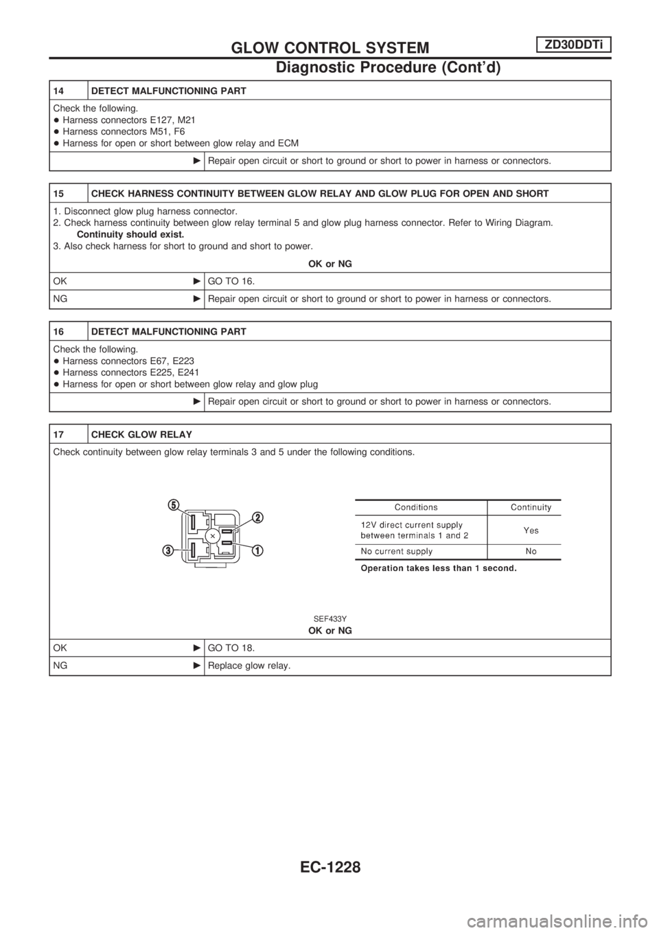
17 CHECK GLOW RELAY
Check continuity between glow relay terminals 3 and 5 under the following conditions.
SEF433Y
OK or NG
OKcGO TO 18.
NGcReplace glow relay.
GLOW CONTROL SYSTEMZD30DDTi
Diagnostic Procedure (Cont'd)
EC-1228
Page 492 of 1033
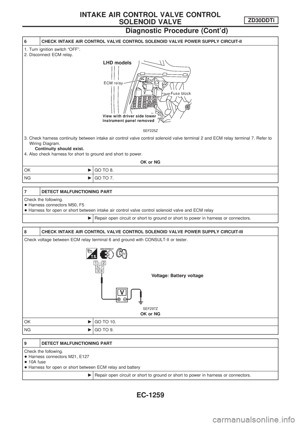
6 CHECK INTAKE AIR CONTROL VALVE CONTROL SOLENOID VALVE POWER SUPPLY CIRCUIT-II
1. Turn ignition switch ªOFFº.
2. Disconnect ECM relay.
SEF225Z
3. Check harness continuity between intake air control valve control solenoid valve terminal 2 and ECM relay terminal 7. Refer to
Wiring Diagram.
Continuity should exist.
4. Also check harness for short to ground and short to power.
OK or NG
OKcGO TO 8.
NGcGO TO 7.
7 DETECT MALFUNCTIONING PART
Check the following.
+Harness connectors M50, F5
+Harness for open or short between intake air control valve control solenoid valve and ECM relay
cRepair open circuit or short to ground or short to power in harness or connectors.
8 CHECK INTAKE AIR CONTROL VALVE CONTROL SOLENOID VALVE POWER SUPPLY CIRCUIT-III
Check voltage between ECM relay terminal 6 and ground with CONSULT-II or tester.
SEF297Z
OK or NG
OKcGO TO 10.
NGcGO TO 9.
9 DETECT MALFUNCTIONING PART
Check the following.
+Harness connectors M21, E127
+10A fuse
+Harness for open or short between ECM relay and battery
cRepair open circuit or short to ground or short to power in harness or connectors.
INTAKE AIR CONTROL VALVE CONTROL
SOLENOID VALVEZD30DDTi
Diagnostic Procedure (Cont'd)
EC-1259
Page 493 of 1033
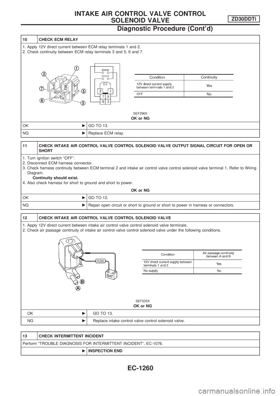
10 CHECK ECM RELAY
1. Apply 12V direct current between ECM relay terminals 1 and 2.
2. Check continuity between ECM relay terminals 3 and 5, 6 and 7.
SEF296X
OK or NG
OKcGO TO 13.
NGcReplace ECM relay.
11 CHECK INTAKE AIR CONTROL VALVE CONTROL SOLENOID VALVE OUTPUT SIGNAL CIRCUIT FOR OPEN OR
SHORT
1. Turn ignition switch ªOFFº.
2. Disconnect ECM harness connector.
3. Check harness continuity between ECM terminal 2 and intake air control valve control solenoid valve terminal 1. Refer to Wiring
Diagram.
Continuity should exist.
4. Also check harness for short to ground and short to power.
OK or NG
OKcGO TO 12.
NGcRepair open circuit or short to ground or short to power in harness or connectors.
12 CHECK INTAKE AIR CONTROL VALVE CONTROL SOLENOID VALVE
1. Apply 12V direct current between intake air control valve control solenoid valve terminals.
2. Check air passage continuity of intake air control valve control solenoid valve under the following conditions.
SEF335X
OK or NG
OKcGO TO 13.
NGcReplace intake control valve control solenoid valve.
13 CHECK INTERMITTENT INCIDENT
Perform ªTROUBLE DIAGNOSIS FOR INTERMITTENT INCIDENTº, EC-1076.
cINSPECTION END
INTAKE AIR CONTROL VALVE CONTROL
SOLENOID VALVEZD30DDTi
Diagnostic Procedure (Cont'd)
EC-1260
Page 565 of 1033
System Description/RHD Models
The cornering lamp operation is controlled by the lighting switch which is built into the combination switch
and cornering lamp relay unit.
Power is supplied at all times
+to lighting switch terminal
V11
+through 10A fuse [No.15, located in the fuse block (J/B)].
Lighting operation by lighting switch
When lighting switch is in 1ST (or 2ND) position, power is supplied
+to cornering lamp relay unit terminal
V3
+through lighting switch terminalV12.
With the ignition switch in the ON or START position, power is supplied to cornering lamp relay unit termi-
nal
V2
+through 7.5A fuse [No.11, located in the fuse block (J/B)].
RH turn
When the turn signal lever is moved to the RH position, ground is supplied
+to cornering lamp relay unit terminal
V6
+through turn signal lamp switch terminalsV2andV1
+through body groundsE25andE40.
Power is supplied
+from terminal
V5of the cornering lamp relay unit
+to front combination lamp RH terminal
V3.
Ground is supplied to terminal
V4of front combination lamp RH through body groundsE25andE40.
The RH cornering lamp illuminates until the turn signal lever returns to NEUTRAL position.
LH turn
When the turn signal lever is moved to the LH position, ground is supplied
+to cornering lamp relay unit terminal
V8
+through turn signal lamp switch terminalsV3andV1
+through body groundsE25andE40.
Power is supplied
+from terminal
V10of the cornering lamp relay unit
+to front combination lamp LH terminal
V3.
Ground is supplied to terminal
V4of front combination lamp LH through body groundsE25andE40.
The LH cornering lamp illuminates until the turn signal lever returns to NEUTRAL position.
CORNERING LAMP
EL-1055
Page 567 of 1033
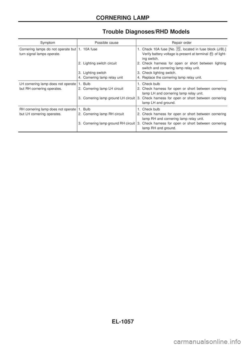
Trouble Diagnoses/RHD Models
Symptom Possible cause Repair order
Cornering lamps do not operate but
turn signal lamps operate.1. 10A fuse
2. Lighting switch circuit
3. Lighting switch
4. Cornering lamp relay unit1. Chack 10A fuse [No.
15, located in fuse block (J/B).]
Verify battery voltage is present at terminal
V11of light-
ing switch.
2. Check harness for open or short between lighting
switch and cornering lamp relay unit.
3. Check lighting switch.
4. Replace the cornering lamp relay unit.
LH cornering lamp does not operate
but RH cornering operates.1. Bulb
2. Cornering lamp LH circuit
3. Cornering lamp ground LH circuit1. Check bulb
2. Check harness for open or short between cornering
lamp LH and cornering lamp relay unit.
3. Check harness for open or short between cornering
lamp LH and ground.
RH cornering lamp does not operate
but LH cornering operates.1. Bulb
2. Cornering lamp RH circuit
3. Cornering lamp ground RH circuit1. Check bulb
2. Check harness for open or short between cornering
lamp RH and cornering lamp relay unit.
3. Check harness for open or short between cornering
lamp RH and ground.
CORNERING LAMP
EL-1057
Page 611 of 1033
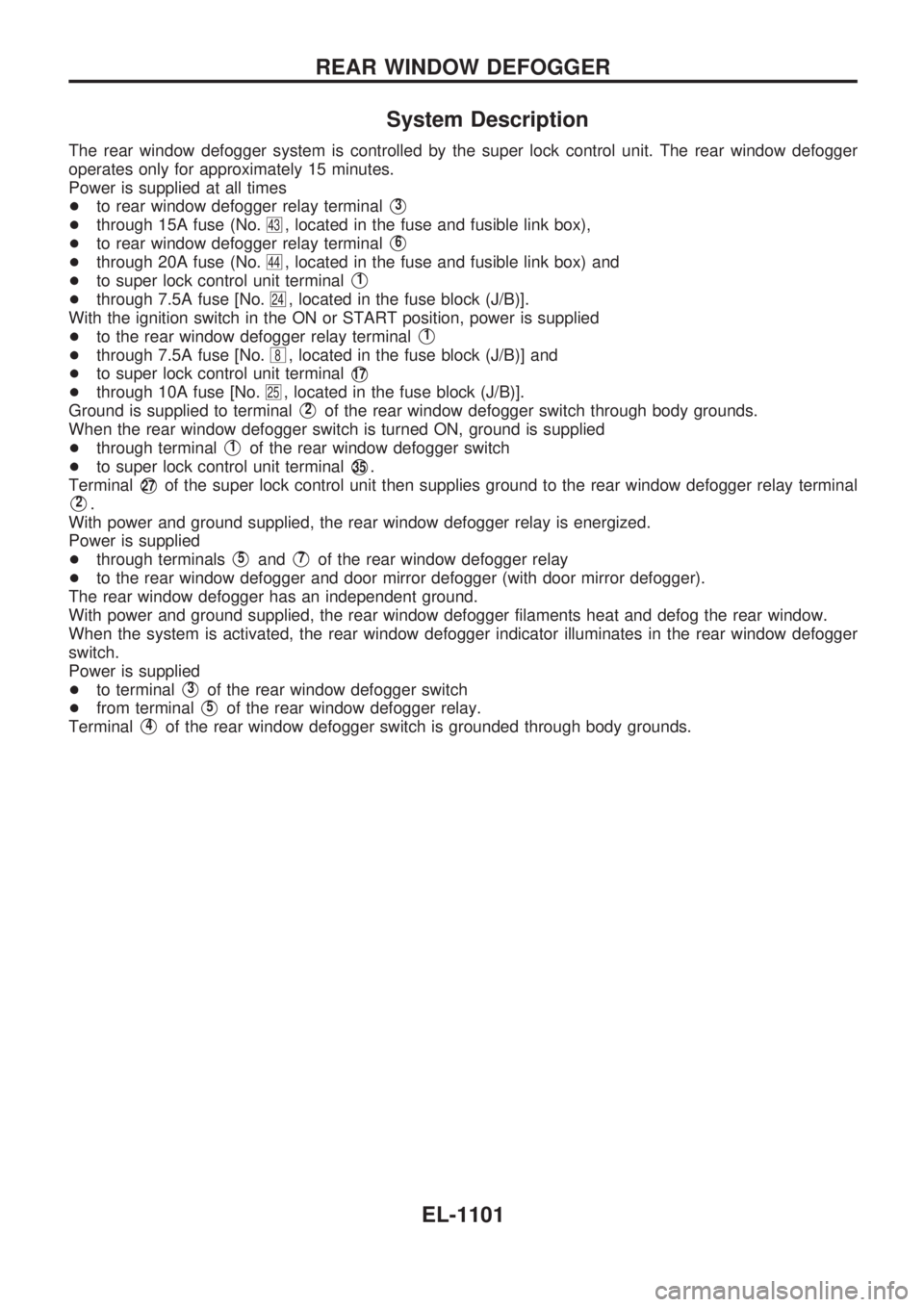
System Description
The rear window defogger system is controlled by the super lock control unit. The rear window defogger
operates only for approximately 15 minutes.
Power is supplied at all times
+to rear window defogger relay terminal
V3
+through 15A fuse (No.43, located in the fuse and fusible link box),
+to rear window defogger relay terminal
V6
+through 20A fuse (No.44, located in the fuse and fusible link box) and
+to super lock control unit terminal
V1
+through 7.5A fuse [No.24, located in the fuse block (J/B)].
With the ignition switch in the ON or START position, power is supplied
+to the rear window defogger relay terminal
V1
+through 7.5A fuse [No.8, located in the fuse block (J/B)] and
+to super lock control unit terminal
V17
+through 10A fuse [No.25, located in the fuse block (J/B)].
Ground is supplied to terminal
V2of the rear window defogger switch through body grounds.
When the rear window defogger switch is turned ON, ground is supplied
+through terminal
V1of the rear window defogger switch
+to super lock control unit terminal
V35.
Terminal
V27of the super lock control unit then supplies ground to the rear window defogger relay terminal
V2.
With power and ground supplied, the rear window defogger relay is energized.
Power is supplied
+through terminals
V5andV7of the rear window defogger relay
+to the rear window defogger and door mirror defogger (with door mirror defogger).
The rear window defogger has an independent ground.
With power and ground supplied, the rear window defogger filaments heat and defog the rear window.
When the system is activated, the rear window defogger indicator illuminates in the rear window defogger
switch.
Power is supplied
+to terminal
V3of the rear window defogger switch
+from terminal
V5of the rear window defogger relay.
Terminal
V4of the rear window defogger switch is grounded through body grounds.
REAR WINDOW DEFOGGER
EL-1101