Page 126 of 1033
Control Valve Assembly and Accumulators
REMOVAL
1. Drain ATF.
2. Remove oil pan and gasket.
3. Remove A/T fluid temperature sensor if necessary.
4. Remove oil strainer.
5. Remove control valve assembly by removing fixing bolts and
disconnecting harness connector.
Bolt length and location
Bolt symbol!mm (in)
VA33 (1.30)
VB45 (1.77)
6. Remove solenoids and valves from valve body if necessary.
7. Remove terminal cord assembly if necessary.
8. Remove accumulator
VA,VB,VCandVDby applying com-
pressed air if necessary.
+Hold each piston with rag.
9. Reinstall any part removed.
+Always use new sealing parts.
SAT260J
SAT073BA
SAT353B
SAT074BA
ON-VEHICLE SERVICE
AT-1124
Page 205 of 1033

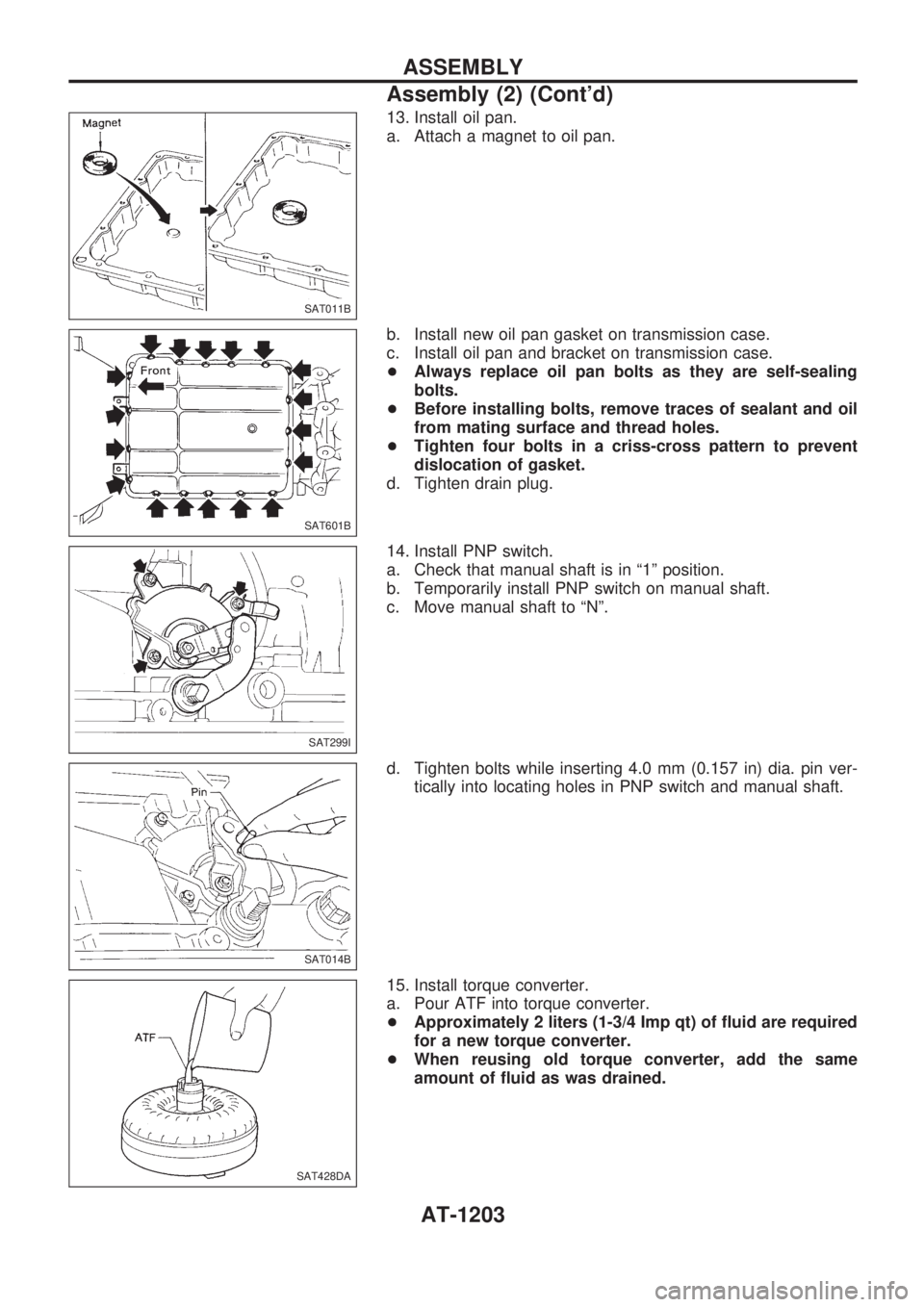
13. Install oil pan.
a. Attach a magnet to oil pan.
b. Install new oil pan gasket on transmission case.
c. Install oil pan and bracket on transmission case.
+Always replace oil pan bolts as they are self-sealing
bolts.
+Before installing bolts, remove traces of sealant and oil
from mating surface and thread holes.
+Tighten four bolts in a criss-cross pattern to prevent
dislocation of gasket.
d. Tighten drain plug.
14. Install PNP switch.
a. Check that manual shaft is in ª1º position.
b. Temporarily install PNP switch on manual shaft.
c. Move manual shaft to ªNº.
d. Tighten bolts while inserting 4.0 mm (0.157 in) dia. pin ver-
tically into locating holes in PNP switch and manual shaft.
15. Install torque converter.
a. Pour ATF into torque converter.
+Approximately 2 liters (1-3/4 Imp qt) of fluid are required
for a new torque converter.
+When reusing old torque converter, add the same
amount of fluid as was drained.
SAT011B
SAT601B
SAT299I
SAT014B
SAT428DA
ASSEMBLY
Assembly (2) (Cont'd)
AT-1203
Page 260 of 1033

REMOVAL
1. Remove the following:
+Engine coolant draining
+Charge air cooler
+Air inlet pipe
+Throttle body
+Rocker cover
+Oil level gauge guide
+EGR guide tube
+EGR volume control solenoid valve
+Fuel hose
+Injection tube
+Radiator upper hose
+Radiator shroud
+Cooling fan
+Drive belt
+Vacuum pipe
+Vacuum pump
2. Move the power steering pump.
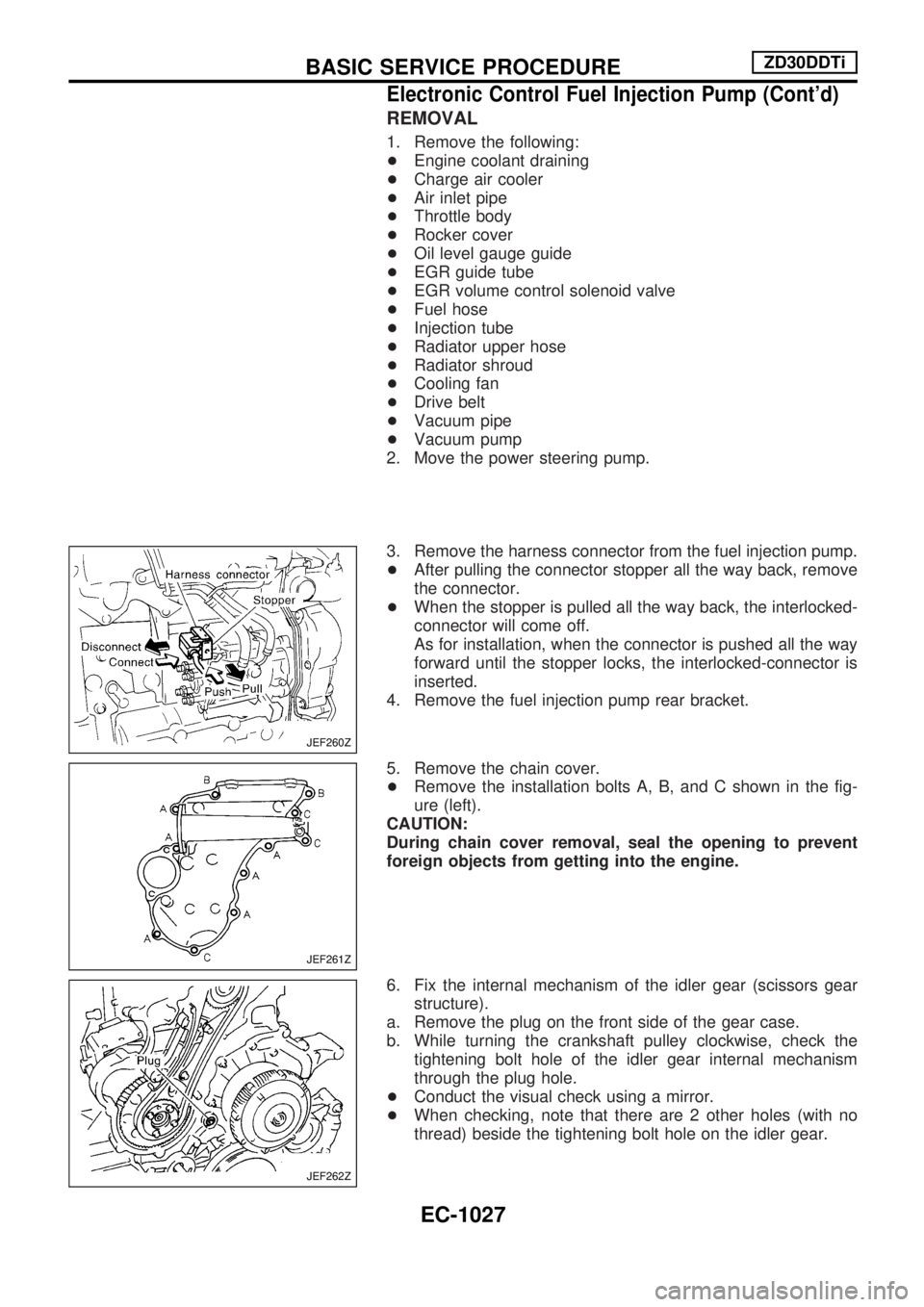
3. Remove the harness connector from the fuel injection pump.
+After pulling the connector stopper all the way back, remove
the connector.
+When the stopper is pulled all the way back, the interlocked-
connector will come off.
As for installation, when the connector is pushed all the way
forward until the stopper locks, the interlocked-connector is
inserted.
4. Remove the fuel injection pump rear bracket.
5. Remove the chain cover.
+Remove the installation bolts A, B, and C shown in the fig-
ure (left).
CAUTION:
During chain cover removal, seal the opening to prevent
foreign objects from getting into the engine.
6. Fix the internal mechanism of the idler gear (scissors gear
structure).
a. Remove the plug on the front side of the gear case.
b. While turning the crankshaft pulley clockwise, check the
tightening bolt hole of the idler gear internal mechanism
through the plug hole.
+Conduct the visual check using a mirror.
+When checking, note that there are 2 other holes (with no
thread) beside the tightening bolt hole on the idler gear.
JEF260Z
JEF261Z
JEF262Z
BASIC SERVICE PROCEDUREZD30DDTi
Electronic Control Fuel Injection Pump (Cont'd)
EC-1027
Page 765 of 1033
Removal and Installation
CAUTION:
As the internal mechanism of the idler gear must first of all,
and always, be set by a bolt when removing the timing chain
before removing the fuel injection pump and timing gear,
follow the procedures on EM-1039, ªRemoval of timing
chain after setting idler gearº, ªElectronic controlled fuel
injection pumpº.
+This chapter will deal with the summary of removing the tim-
ing chain before removing the camshaft and cylinder head.
Removal
1. Remove the following parts.
+Engine cover
+Intercooler
+Air inlet pipe
+Throttle body
+Rocker cover
+Spill tube
+Coolant (Drain)
+Radiator upper hose
+Water outlet
+Radiator shroud
+Cooling fan
+Auxilary belt
FEM003
TIMING CHAINZD
EM-1027
Page 778 of 1033

Removal
1. Remove the following parts.
+Undercover
+Engine oil (Drain)
+Engine coolant (Drain)
+Engine cover
+Intercooler
+Air inlet pipe
+Air cleaner case
+Throttle body
+Swirl and intake air control valve control solenoid valve and
bracket
+Vacuum tank
+Glow plate
+Rocker cover
+Spill tube
+Radiator shrouds (Rear and Lower)
+Cooling fan
+Radiator hose (Upper and Lower)
+Auxiliary belt and auto tensioner.
2. Remove the alternator.
3. Remove the A/C compressor and bracket with piping con-
nected. Move and support it at the LH side of engine bay with
a rope to avoid putting load on piping.
Refer to HA section in Nissan Service Manual (Supplement
I: Publication No. SM0E-Y61AE0E.)
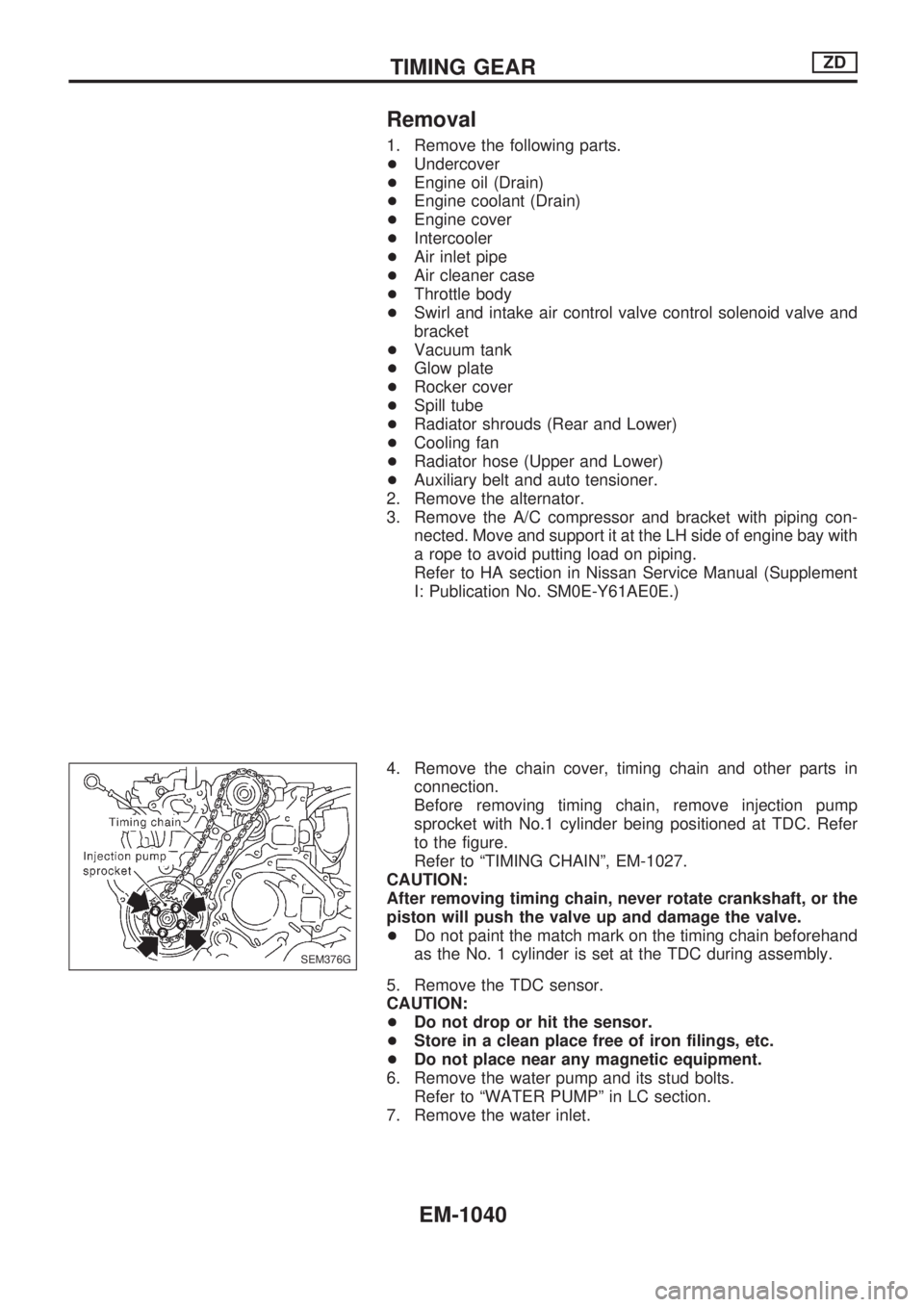
4. Remove the chain cover, timing chain and other parts in
connection.
Before removing timing chain, remove injection pump
sprocket with No.1 cylinder being positioned at TDC. Refer
to the figure.
Refer to ªTIMING CHAINº, EM-1027.
CAUTION:
After removing timing chain, never rotate crankshaft, or the
piston will push the valve up and damage the valve.
+Do not paint the match mark on the timing chain beforehand
as the No. 1 cylinder is set at the TDC during assembly.
5. Remove the TDC sensor.
CAUTION:
+Do not drop or hit the sensor.
+Store in a clean place free of iron filings, etc.
+Do not place near any magnetic equipment.
6. Remove the water pump and its stud bolts.
Refer to ªWATER PUMPº in LC section.
7. Remove the water inlet.
SEM376G
TIMING GEARZD
EM-1040
Page 791 of 1033
Removal and Installation
Removal
1. Remove the following. (Refer to corresponding chapter for
detailed auxiliary work.)
+Drain coolant
+Rocker cover
+Injection tube
+Spill tube
+High pressure injection nozzle assembly
+Timing chain
+Camshaft
+Catalytic converter
+Turbocharger assembly
+Exhaust manifold
2. Remove mounting bolts of the gear case and water pump as
shown by arrows in the figure.
3. Remove oil return pipe from the rear side of cylinder head.
4. Remove intake manifold.
SEM359G
FEM054
CYLINDER HEADZD
EM-1053
Page 807 of 1033

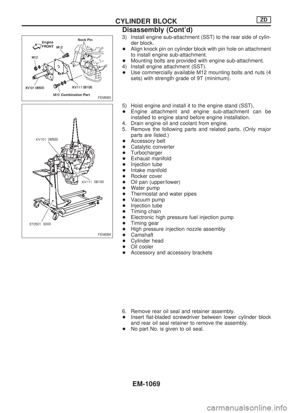
3) Install engine sub-attachment (SST) to the rear side of cylin-
der block.
+Align knock pin on cylinder block with pin hole on attachment
to install engine sub-attachment.
+Mounting bolts are provided with engine sub-attachment.
4) Install engine attachment (SST).
+Use commercially available M12 mounting bolts and nuts (4
sets) with strength grade of 9T (minimum).
5) Hoist engine and install it to the engine stand (SST).
+Engine attachment and engine sub-attachment can be
installed to engine stand before engine installation.
4. Drain engine oil and coolant from engine.
5. Remove the following parts and related parts. (Only major
parts are listed.)
+Accessory belt
+Catalytic converter
+Turbocharger
+Exhaust manifold
+Injection tube
+Intake manifold
+Rocker cover
+Oil pan (upper/lower)
+Water pump
+Thermostat and water pipes
+Vacuum pump
+Injection tube
+Timing chain
+Electronic high pressure fuel injection pump
+Timing gear
+High pressure injection nozzle assembly
+Camshaft
+Cylinder head
+Oil cooler
+Accessory and accessory brackets
6. Remove rear oil seal and retainer assembly.
+Insert flat-bladed screwdriver between lower cylinder block
and rear oil seal retainer to remove the assembly.
+No part No. is given to oil seal.
FEM083
FEM084
CYLINDER BLOCKZD
Disassembly (Cont'd)
EM-1069
Page 890 of 1033
OIL FILTER
The oil filter is an element type. Refer to ªChanging Oil Filterº in
MA section.
Oil Cooler
REMOVAL AND INSTALLATION
1. Drain engine oil and coolant.
Remove catalyst and turbocharger. Refer to ªCATALYST
AND TURBOCHARGERº in EM section.
2. Remove bolts A to C then remove oil cooler assembly.
+Do not remove ªDº nuts when removing oil cooler
assembly.
Bolt length:
A: 20 mm (0.79 in)
B: 45 mm (1.77 in)
C: 65 mm (2.56 in)
3. Installation is in reverse order of removal.
+Do not spill coolant on the drive belt.
INSPECTION
1. Check oil cooler for cracks.
2. Check oil cooler for clogging by blowing through coolant inlet.
If necessary, replace oil cooler assembly.
JLC370B
JLC381B
ENGINE LUBRICATION SYSTEMZD
Oil Jet (Cont'd)
LC-1007