2000 NISSAN PATROL air conditioning
[x] Cancel search: air conditioningPage 234 of 1033

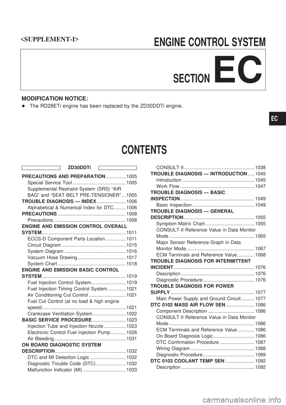
ENGINE CONTROL SYSTEM
SECTION
EC
MODIFICATION NOTICE:
+The RD28ETi engine has been replaced by the ZD30DDTi engine.
CONTENTS
ZD30DDTi
PRECAUTIONS AND PREPARATION............... 1005
Special Service Tool ........................................ 1005
Supplemental Restraint System (SRS) ªAIR
BAGº and ªSEAT BELT PRE-TENSIONERº ... 1005
TROUBLE DIAGNOSIS Ð INDEX...................... 1006
Alphabetical & Numerical Index for DTC......... 1006
PRECAUTIONS................................................... 1008
Precautions ...................................................... 1008
ENGINE AND EMISSION CONTROL OVERALL
SYSTEM............................................................... 1011
ECCS-D Component Parts Location ............... 1011
Circuit Diagram ................................................ 1015
System Diagram .............................................. 1016
Vacuum Hose Drawing .................................... 1017
System Chart ................................................... 1018
ENGINE AND EMISSION BASIC CONTROL
SYSTEM............................................................... 1019
Fuel Injection Control System.......................... 1019
Fuel Injection Timing Control System.............. 1021
Air Conditioning Cut Control ............................ 1021
Fuel Cut Control (at no load & high engine
speed) .............................................................. 1021
Crankcase Ventilation System ......................... 1022
BASIC SERVICE PROCEDURE......................... 1023
Injection Tube and Injection Nozzle ................ 1023
Electronic Control Fuel Injection Pump ........... 1026
Air Bleeding...................................................... 1031
ON BOARD DIAGNOSTIC SYSTEM
DESCRIPTION..................................................... 1032
DTC and MI Detection Logic ........................... 1032
Diagnostic Trouble Code (DTC) ...................... 1032
Malfunction Indicator (MI) ................................ 1033CONSULT-II ..................................................... 1038
TROUBLE DIAGNOSIS Ð INTRODUCTION..... 1045
Introduction ...................................................... 1045
Work Flow ........................................................ 1047
TROUBLE DIAGNOSIS Ð BASIC
INSPECTION........................................................ 1049
Basic Inspection ............................................... 1049
TROUBLE DIAGNOSIS Ð GENERAL
DESCRIPTION..................................................... 1055
Symptom Matrix Chart ..................................... 1055
CONSULT-II Reference Value in Data Monitor
Mode ................................................................ 1065
Major Sensor Reference Graph in Data
Monitor Mode ................................................... 1067
ECM Terminals and Reference Value ............. 1068
TROUBLE DIAGNOSIS FOR INTERMITTENT
INCIDENT............................................................. 1076
Description ....................................................... 1076
Diagnostic Procedure....................................... 1076
TROUBLE DIAGNOSIS FOR POWER
SUPPLY............................................................... 1077
Main Power Supply and Ground Circuit .......... 1077
DTC 0102 MASS AIR FLOW SEN...................... 1086
Component Description ................................... 1086
CONSULT-II Reference Value in Data Monitor
Mode ................................................................ 1086
ECM Terminals and Reference Value ............. 1086
On Board Diagnosis Logic ............................... 1086
DTC Confirmation Procedure .......................... 1087
Wiring Diagram ................................................ 1088
Diagnostic Procedure....................................... 1089
DTC 0103 COOLANT TEMP SEN...................... 1092
Description ....................................................... 1092
EC
Page 251 of 1033

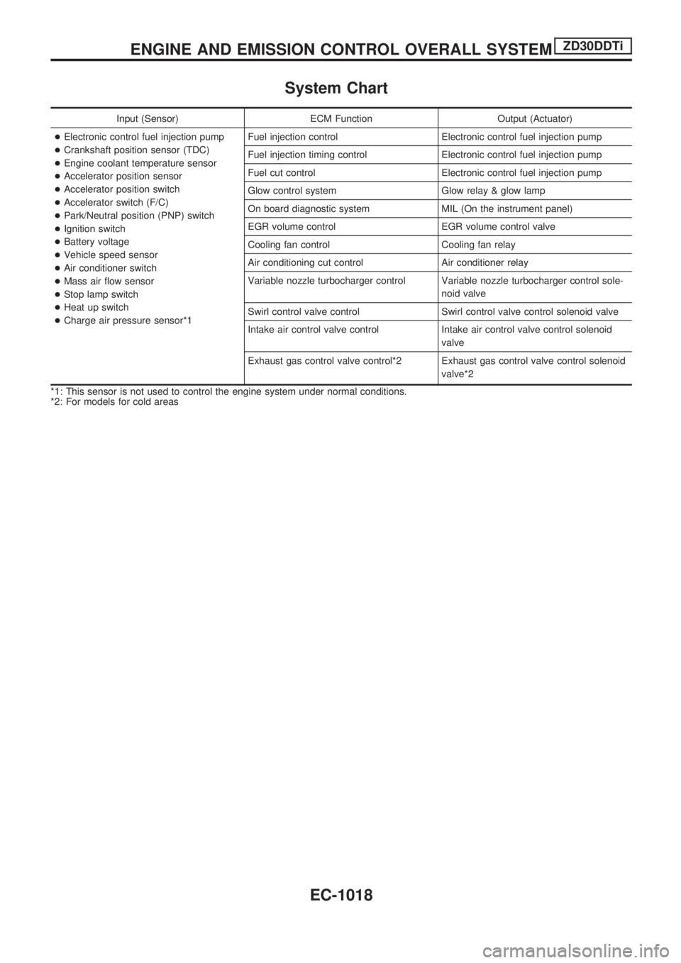
System Chart
Input (Sensor) ECM Function Output (Actuator)
+Electronic control fuel injection pump
+Crankshaft position sensor (TDC)
+Engine coolant temperature sensor
+Accelerator position sensor
+Accelerator position switch
+Accelerator switch (F/C)
+Park/Neutral position (PNP) switch
+Ignition switch
+Battery voltage
+Vehicle speed sensor
+Air conditioner switch
+Mass air flow sensor
+Stop lamp switch
+Heat up switch
+Charge air pressure sensor*1Fuel injection control Electronic control fuel injection pump
Fuel injection timing control Electronic control fuel injection pump
Fuel cut control Electronic control fuel injection pump
Glow control system Glow relay & glow lamp
On board diagnostic system MIL (On the instrument panel)
EGR volume control EGR volume control valve
Cooling fan control Cooling fan relay
Air conditioning cut control Air conditioner relay
Variable nozzle turbocharger control Variable nozzle turbocharger control sole-
noid valve
Swirl control valve control Swirl control valve control solenoid valve
Intake air control valve control Intake air control valve control solenoid
valve
Exhaust gas control valve control*2 Exhaust gas control valve control solenoid
valve*2
*1: This sensor is not used to control the engine system under normal conditions.
*2: For models for cold areas
ENGINE AND EMISSION CONTROL OVERALL SYSTEMZD30DDTi
EC-1018
Page 254 of 1033

Fuel Injection Timing Control System
DESCRIPTION
The target fuel injection timing in accordance with the engine speed and the fuel injection amount are
recorded as a map in the ECM beforehand. The ECM and the injection pump control unit exchange signals
and perform feedback control for optimum injection timing in accordance with the map.
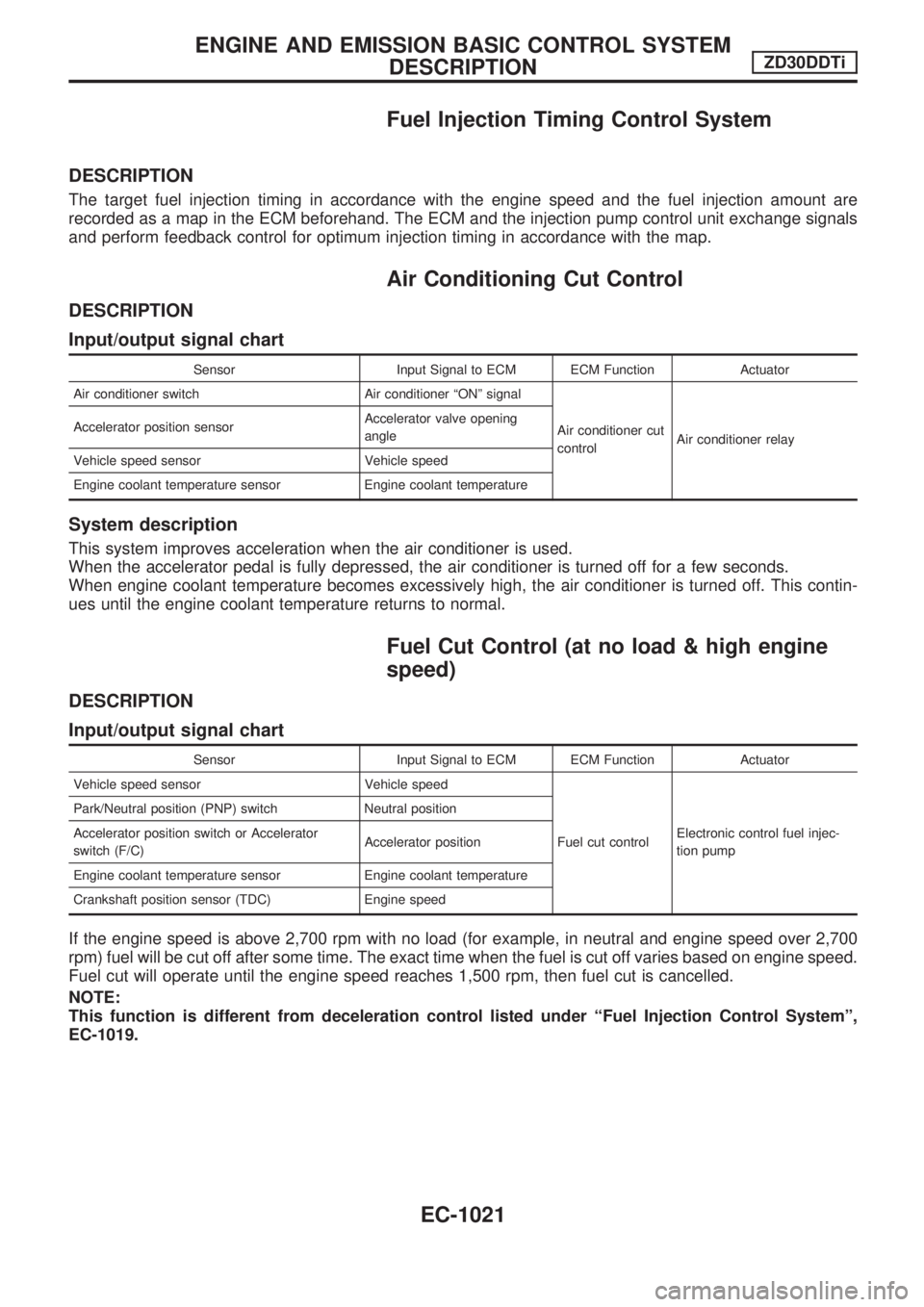
Air Conditioning Cut Control
DESCRIPTION
Input/output signal chart
Sensor Input Signal to ECM ECM Function Actuator
Air conditioner switch Air conditioner ªONº signal
Air conditioner cut
controlAir conditioner relay Accelerator position sensorAccelerator valve opening
angle
Vehicle speed sensor Vehicle speed
Engine coolant temperature sensor Engine coolant temperature
System description
This system improves acceleration when the air conditioner is used.
When the accelerator pedal is fully depressed, the air conditioner is turned off for a few seconds.
When engine coolant temperature becomes excessively high, the air conditioner is turned off. This contin-
ues until the engine coolant temperature returns to normal.
Fuel Cut Control (at no load & high engine
speed)
DESCRIPTION
Input/output signal chart
Sensor Input Signal to ECM ECM Function Actuator
Vehicle speed sensor Vehicle speed
Fuel cut controlElectronic control fuel injec-
tion pump Park/Neutral position (PNP) switch Neutral position
Accelerator position switch or Accelerator
switch (F/C)Accelerator position
Engine coolant temperature sensor Engine coolant temperature
Crankshaft position sensor (TDC) Engine speed
If the engine speed is above 2,700 rpm with no load (for example, in neutral and engine speed over 2,700
rpm) fuel will be cut off after some time. The exact time when the fuel is cut off varies based on engine speed.
Fuel cut will operate until the engine speed reaches 1,500 rpm, then fuel cut is cancelled.
NOTE:
This function is different from deceleration control listed under ªFuel Injection Control Systemº,
EC-1019.
ENGINE AND EMISSION BASIC CONTROL SYSTEM
DESCRIPTIONZD30DDTi
EC-1021
Page 906 of 1033

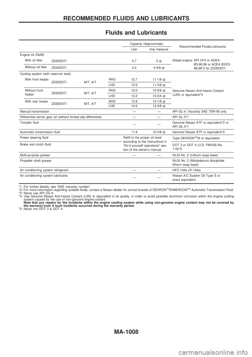
Fluids and Lubricants
Capacity (Approximate)
Recommended Fluids/Lubricants
Liter Imp measure
Engine oil (Refill)
With oil filter
ZD30DDTi 5.7 5 qtDiesel engine: API CF4 or ACEA
B3-96.98 or ACEA B3/E3-
96.98*3 for ZD30DDTi Without oil filter
ZD30DDTi 5.2 4-5/8 qt
Cooling system (with reservoir tank)
With front heater
ZD30DDTi M/T, A/TRHD 12.7 11-1/8 qt
Genuine Nissan Anti-freeze Coolant
(L2N) or equivalent*4 LHD 12.9 11-3/8 qt
Without front
heaterZD30DDTi M/T, A/TRHD 12.0 10-5/8 qt
LHD 12.2 10-3/4 qt
With rear heater
ZD30DDTi M/T, A/TRHD 13.8 12-1/8 qt
LHD 14.0 12-3/8 qt
Manual transmission Ð Ð API GL-4, Viscosity SAE 75W-90 only
Differential carrier gear oil (without limited slip differential) Ð Ð API GL-5*1
Transfer fluid
ÐÐGenuine Nissan ATF or equivalent*2 or
API GL-4*1
Automatic transmission fluid 11.8 10-3/8 qt Genuine Nissan ATF or equivalent*2
Power steering fluid Refill to the proper oil level
according to the instructions in
ªDo-it-yourself operationsº sec-
tion of the owner's manual.Type DEXRON
TMIII or equivalent
Brake and clutch fluid
DOT 3 or DOT 4 (U.S. FMVSS No.
116)*5
Multi-purpose grease Ð Ð NLGI No. 2 (Lithium soap base)
Propeller shaft greaseNLGI No. 2 (Molybdenum disulphide
lithium soap base)
Air conditioning system refrigerant Ð Ð HFC-134a (R-134a)
Air conditioning system lubricants
ÐÐNissan A/C System Oil Type S or
exact equivalent
*1: For further details, see ªSAE viscosity numberº.
*2: For more information regarding suitable fluids, contact a Nissan dealer for correct brands of DEXRON
TMIII/MERCONTMAutomatic Transmission Fluid.
*3: Never use API CG-4.
*4: Use Genuine Nissan Anti-freeze Coolant (L2N) or equivalent in its quality, in order to avoid possible aluminum corrosion within the engine cooling
system caused by the use of non-genuine engine coolant.
Note that any repairs for the incidents within the engine cooling system while using non-genuine engine coolant may not be covered by
the warranty even if such incidents occurred during the warranty period.
*5: Never mix DOT 3 & DOT 4.
RECOMMENDED FLUIDS AND LUBRICANTS
MA-1008