2000 NISSAN PATROL transmission
[x] Cancel search: transmissionPage 1 of 1033
Edition: February 2000
Release: February 2000 (01)
Publication No.: SM0E-Y61AE0E
Reference No.: 7711346024GENERAL INFORMATIONGI
MAINTENANCEMA
ENGINE MECHANICALEM
ENGINE LUBRICATION &
COOLING SYSTEMSLC
ENGINE CONTROL SYSTEMEC
ACCELERATOR CONTROL,
FUEL & EXHAUST SYSTEMFE
CLUTCHCL
MANUAL TRANSMISSIONMT
AUTOMATIC TRANSMISSIONAT
TRANSFERTF
PROPELLER SHAFT &
DIFFERENTIAL CARRIERPD
FRONT AXLE & FRONT SUSPENSIONFA
REAR AXLE & REAR SUSPENSIONRA
BRAKE SYSTEMBR
STEERING SYSTEMST
RESTRAINT SYSTEMRS
BODY & TRIMBT
HEATER & AIR CONDITIONERHA
ELECTRICAL SYSTEMEL
ALPHABETICAL INDEXIDX
PATROL GR
MODEL Y61 SERIES
NISSAN EUROPE S.A.S.
2000 NISSAN EUROPE S.A.S.
Produced in The Netherlands
Not to be reproduced in whole or in part
without the prior written permission of
Nissan Europe S.A.S., Paris, France.
QUICK REFERENCE INDEX
Page 3 of 1033

AUTOMATIC TRANSMISSION
SECTION
AT
CONTENTS
PREPARATION AND PRECAUTIONS............... 1003
Special Service Tools ...................................... 1003
Supplemental Restraint System (SRS) ªAIR
BAGº and ªSEAT BELT PRE-TENSIONERº ... 1004
Precautions ...................................................... 1004
Service Notice or Precautions ......................... 1006
OVERALL SYSTEM............................................ 1007
A/T Electrical Parts Location ........................... 1007
Circuit Diagram ................................................ 1008
Wiring Diagram Ð A/T Ð ................................ 1009
Cross-sectional View ....................................... 1022
Hydraulic Control Circuits ................................ 1023
Shift Mechanism .............................................. 1024
Control System ................................................ 1026
ON BOARD DIAGNOSTIC SYSTEM
DESCRIPTION..................................................... 1028
Self-diagnosis................................................... 1028
Diagnosis by CONSULT-II ............................... 1034
TROUBLE DIAGNOSIS Ð Introduction............ 1036
Introduction ...................................................... 1036
Diagnostic Worksheet ...................................... 1037
Work Flow ........................................................ 1040
TROUBLE DIAGNOSIS Ð Basic Inspection.... 1041
A/T Fluid Check ............................................... 1041
Stall Test .......................................................... 1041
Line Pressure Test........................................... 1044
Road Test ........................................................ 1046
TROUBLE DIAGNOSIS Ð General
Description.......................................................... 1057
Symptom Chart ................................................ 1057
TCM Terminals and Reference Value ............. 1060
TROUBLE DIAGNOSIS FOR VHCL SPEED
SENzA/T................................................................ 1064Vehicle Speed SensorzA/T (Revolution
sensor) ............................................................. 1064
TROUBLE DIAGNOSIS FOR VHCL SPEED
SENzMTR.............................................................. 1066
Vehicle Speed SensorzzMTR ............................ 1066
TROUBLE DIAGNOSIS FOR THROTTLE POSI
SEN...................................................................... 1068
Accelerator Position Sensor ............................ 1068
TROUBLE DIAGNOSIS FOR SHIFT
SOLENOID/V A.................................................... 1070
Shift Solenoid Valve A ..................................... 1070
TROUBLE DIAGNOSIS FOR SHIFT
SOLENOID/V B.................................................... 1072
Shift Solenoid Valve B ..................................... 1072
TROUBLE DIAGNOSIS FOR OVERRUN
CLUTCH S/V........................................................ 1074
Overrun Clutch Solenoid Valve ....................... 1074
TROUBLE DIAGNOSIS FOR T/C CLUTCH
SOL/V................................................................... 1076
Torque Converter Clutch Solenoid Valve ........ 1076
TROUBLE DIAGNOSIS FOR BATT/FLUID
TEMP SEN........................................................... 1079
A/T Fluid Temperature Sensor and TCM
Power Source .................................................. 1079
TROUBLE DIAGNOSIS FOR ENGINE SPEED
SIG....................................................................... 1082
Engine Speed Signal ....................................... 1082
TROUBLE DIAGNOSIS FOR LINE PRESSURE
S/V........................................................................ 1084
Line Pressure Solenoid Valve ......................... 1084
TROUBLE DIAGNOSIS FOR CONTROL UNIT
(RAM), CONTROL UNIT (ROM)......................... 1087
Description ....................................................... 1087
AT
Page 5 of 1033
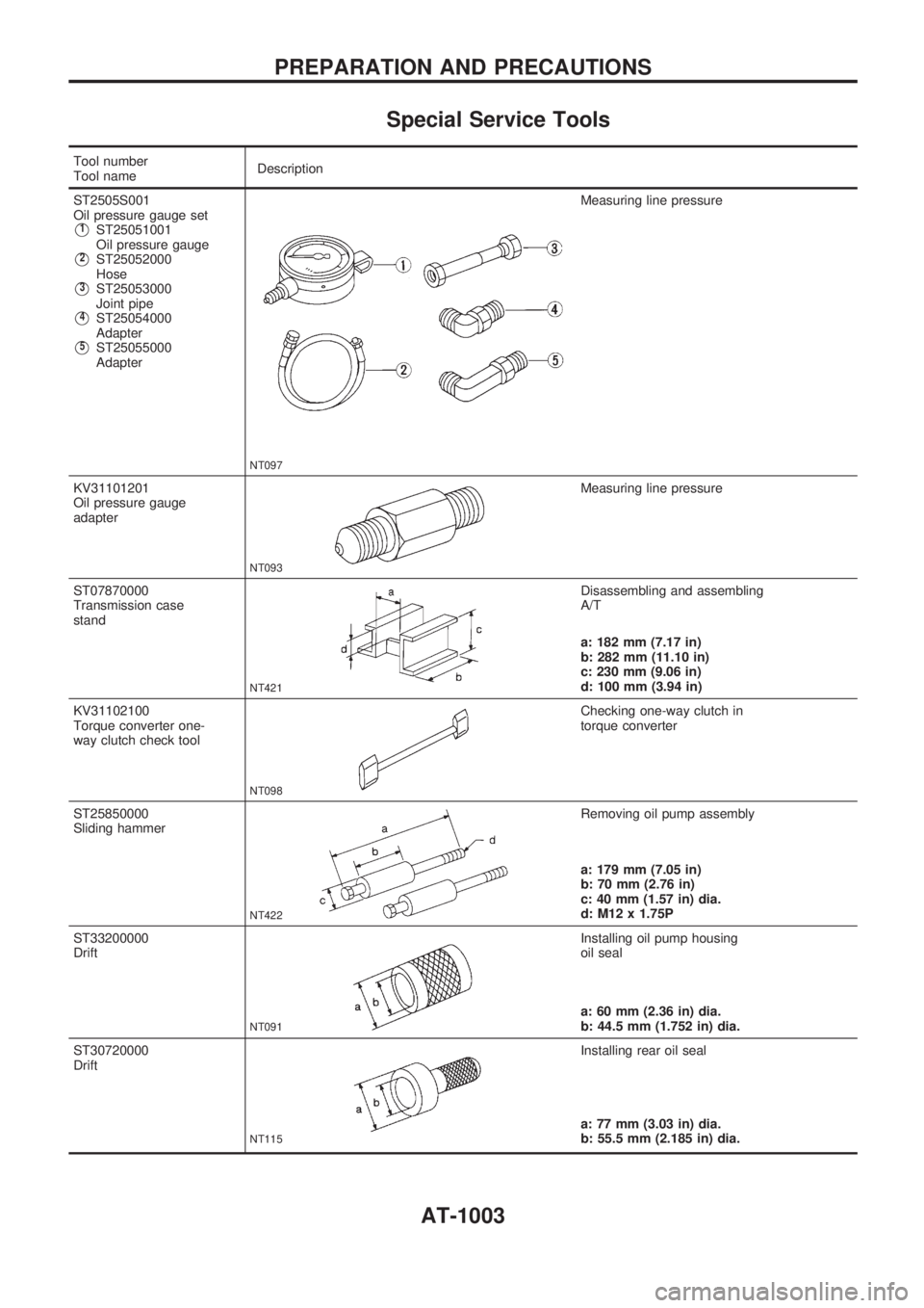
Special Service Tools
Tool number
Tool nameDescription
ST2505S001
Oil pressure gauge set
V1ST25051001
Oil pressure gauge
V2ST25052000
Hose
V3ST25053000
Joint pipe
V4ST25054000
Adapter
V5ST25055000
Adapter
NT097
Measuring line pressure
KV31101201
Oil pressure gauge
adapter
NT093
Measuring line pressure
ST07870000
Transmission case
stand
NT421
Disassembling and assembling
A/T
a: 182 mm (7.17 in)
b: 282 mm (11.10 in)
c: 230 mm (9.06 in)
d: 100 mm (3.94 in)
KV31102100
Torque converter one-
way clutch check tool
NT098
Checking one-way clutch in
torque converter
ST25850000
Sliding hammer
NT422
Removing oil pump assembly
a: 179 mm (7.05 in)
b: 70 mm (2.76 in)
c: 40 mm (1.57 in) dia.
d: M12 x 1.75P
ST33200000
Drift
NT091
Installing oil pump housing
oil seal
a: 60 mm (2.36 in) dia.
b: 44.5 mm (1.752 in) dia.
ST30720000
Drift
NT115
Installing rear oil seal
a: 77 mm (3.03 in) dia.
b: 55.5 mm (2.185 in) dia.
PREPARATION AND PRECAUTIONS
AT-1003
Page 6 of 1033
Tool number
Tool nameDescription
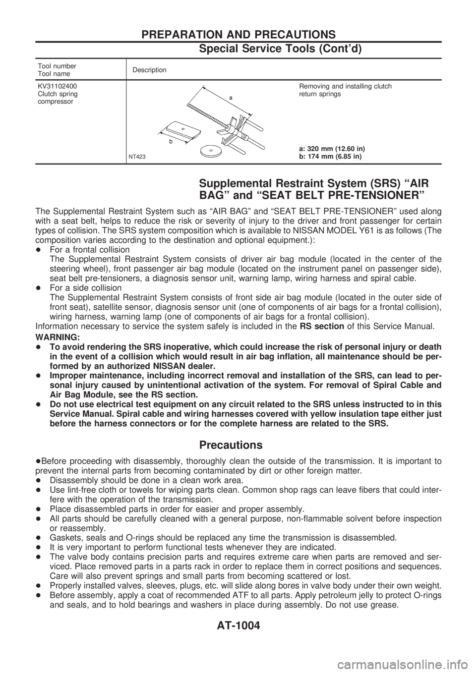
KV31102400
Clutch spring
compressor
NT423
Removing and installing clutch
return springs
a: 320 mm (12.60 in)
b: 174 mm (6.85 in)
Supplemental Restraint System (SRS) ªAIR
BAGº and ªSEAT BELT PRE-TENSIONERº
The Supplemental Restraint System such as ªAIR BAGº and ªSEAT BELT PRE-TENSIONERº used along
with a seat belt, helps to reduce the risk or severity of injury to the driver and front passenger for certain
types of collision. The SRS system composition which is available to NISSAN MODEL Y61 is as follows (The
composition varies according to the destination and optional equipment.):
+For a frontal collision
The Supplemental Restraint System consists of driver air bag module (located in the center of the
steering wheel), front passenger air bag module (located on the instrument panel on passenger side),
seat belt pre-tensioners, a diagnosis sensor unit, warning lamp, wiring harness and spiral cable.
+For a side collision
The Supplemental Restraint System consists of front side air bag module (located in the outer side of
front seat), satellite sensor, diagnosis sensor unit (one of components of air bags for a frontal collision),
wiring harness, warning lamp (one of components of air bags for a frontal collision).
Information necessary to service the system safely is included in theRS sectionof this Service Manual.
WARNING:
+To avoid rendering the SRS inoperative, which could increase the risk of personal injury or death
in the event of a collision which would result in air bag inflation, all maintenance should be per-
formed by an authorized NISSAN dealer.
+Improper maintenance, including incorrect removal and installation of the SRS, can lead to per-
sonal injury caused by unintentional activation of the system. For removal of Spiral Cable and
Air Bag Module, see the RS section.
+Do not use electrical test equipment on any circuit related to the SRS unless instructed to in this
Service Manual. Spiral cable and wiring harnesses covered with yellow insulation tape either just
before the harness connectors or for the complete harness are related to the SRS.
Precautions
+Before proceeding with disassembly, thoroughly clean the outside of the transmission. It is important to
prevent the internal parts from becoming contaminated by dirt or other foreign matter.
+Disassembly should be done in a clean work area.
+Use lint-free cloth or towels for wiping parts clean. Common shop rags can leave fibers that could inter-
fere with the operation of the transmission.
+Place disassembled parts in order for easier and proper assembly.
+All parts should be carefully cleaned with a general purpose, non-flammable solvent before inspection
or reassembly.
+Gaskets, seals and O-rings should be replaced any time the transmission is disassembled.
+It is very important to perform functional tests whenever they are indicated.
+The valve body contains precision parts and requires extreme care when parts are removed and ser-
viced. Place removed parts in a parts rack in order to replace them in correct positions and sequences.
Care will also prevent springs and small parts from becoming scattered or lost.
+Properly installed valves, sleeves, plugs, etc. will slide along bores in valve body under their own weight.
+Before assembly, apply a coat of recommended ATF to all parts. Apply petroleum jelly to protect O-rings
and seals, and to hold bearings and washers in place during assembly. Do not use grease.
PREPARATION AND PRECAUTIONS
Special Service Tools (Cont'd)
AT-1004
Page 7 of 1033
+Extreme care should be taken to avoid damage to O-rings, seals and gaskets when assembling.
+After overhaul, refill the transmission with new ATF.
+When the A/T drain plug is removed, only some of the fluid is drained. Old A/T fluid will remain in torque
converter and ATF cooling system.
Always follow the procedures under ªChanging A/T Fluidº in the MA section when changing A/T fluid.
PREPARATION AND PRECAUTIONS
Precautions (Cont'd)
AT-1005
Page 26 of 1033
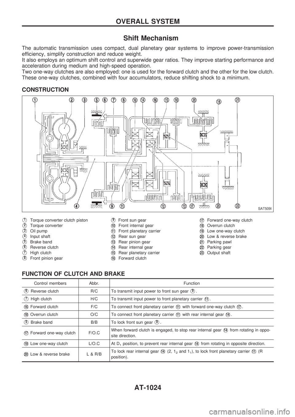
Shift Mechanism
The automatic transmission uses compact, dual planetary gear systems to improve power-transmission
efficiency, simplify construction and reduce weight.
It also employs an optimum shift control and superwide gear ratios. They improve starting performance and
acceleration during medium and high-speed operation.
Two one-way clutches are also employed: one is used for the forward clutch and the other for the low clutch.
These one-way clutches, combined with four accumulators, reduce shifting shock to a minimum.
CONSTRUCTION
V1Torque converter clutch piston
V2Torque converter
V3Oil pump
V4Input shaft
V5Brake band
V6Reverse clutch
V7High clutch
V8Front pinion gear
V9Front sun gear
V10Front internal gear
V11Front planetary carrier
V12Rear sun gear
V13Rear pinion gear
V14Rear internal gear
V15Rear planetary carrier
V16Forward clutch
V17Forward one-way clutch
V18Overrun clutch
V19Low one-way clutch
V20Low & reverse brake
V21Parking pawl
V22Parking gear
V23Output shaft
FUNCTION OF CLUTCH AND BRAKE
Control members Abbr. Function
V6Reverse clutch R/C To transmit input power to front sun gearV9.
V7High clutch H/C To transmit input power to front planetary carrierV11.
V16Forward clutch F/C To connect front planetary carrierV11with forward one-way clutchV17.
V18Overrun clutch O/C To connect front planetary carrierV11with rear internal gearV14.
V5Brake band B/B To lock front sun gearV9.
V17Forward one-way clutch F/O.CWhen forward clutch is engaged, to stop rear internal gearV14from rotating in oppo-
site direction.
V19Low one-way clutch L/O.C At D1position, to prevent rear internal gearV14from rotating in opposite direction.
V20Low & reverse brake L & R/BTo lock rear internal gearV14(2, 12and 11), to lock front planetary carrierV11(R
position).
SAT509I
OVERALL SYSTEM
AT-1024
Page 27 of 1033
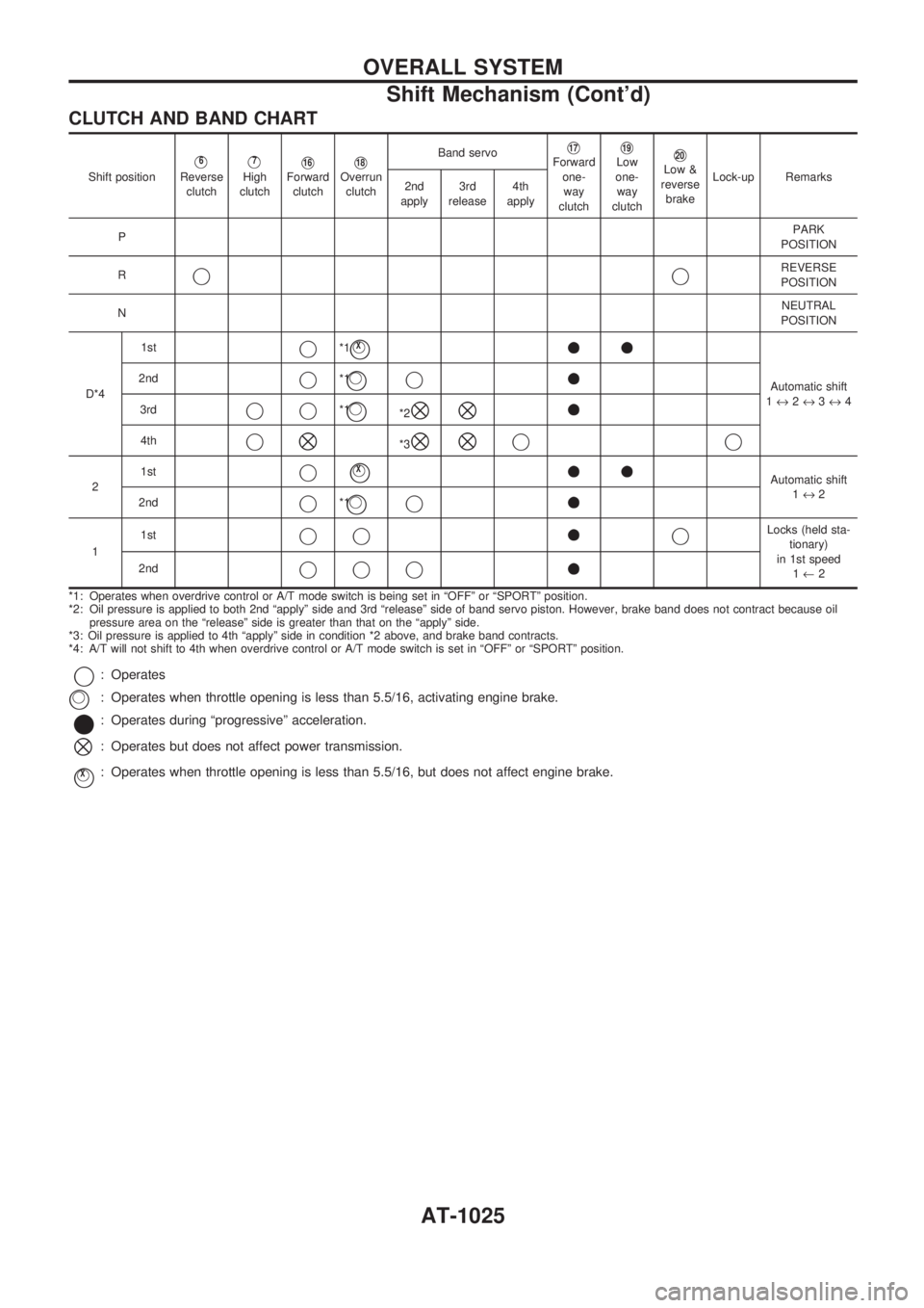
CLUTCH AND BAND CHART
Shift positionV6
Reverse
clutchV7
High
clutchV16Forward
clutchV18Overrun
clutchBand servo
V17Forward
one-
way
clutchV19Low
one-
way
clutchV20Low &
reverse
brakeLock-up Remarks
2nd
apply3rd
release4th
apply
PPARK
POSITION
R
jjREVERSE
POSITION
NNEUTRAL
POSITION
D*41st
j*1jVX++
Automatic shift
1«2«3«4 2ndj*1jVj+
3rdjj*1jV*2^^+
4thj^*3^^jj
21stjjVX++Automatic shift
1«2
2nd
j*1jVj+
11stjj+jLocks (held sta-
tionary)
in 1st speed
1¬2 2nd
jjj+
*1: Operates when overdrive control or A/T mode switch is being set in ªOFFº or ªSPORTº position.
*2: Oil pressure is applied to both 2nd ªapplyº side and 3rd ªreleaseº side of band servo piston. However, brake band does not contract because oil
pressure area on the ªreleaseº side is greater than that on the ªapplyº side.
*3: Oil pressure is applied to 4th ªapplyº side in condition *2 above, and brake band contracts.
*4: A/T will not shift to 4th when overdrive control or A/T mode switch is set in ªOFFº or ªSPORTº position.
j: Operates
: Operates when throttle opening is less than 5.5/16, activating engine brake.
*: Operates during ªprogressiveº acceleration.
^: Operates but does not affect power transmission.
jVX: Operates when throttle opening is less than 5.5/16, but does not affect engine brake.
jV
OVERALL SYSTEM
Shift Mechanism (Cont'd)
AT-1025
Page 28 of 1033
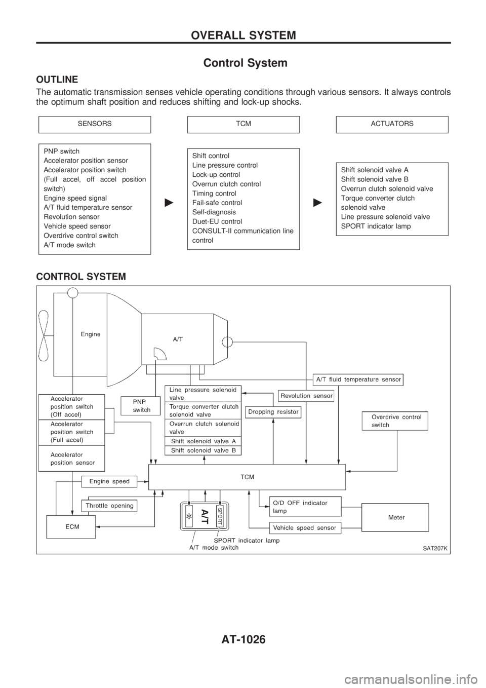
Control System
OUTLINE
The automatic transmission senses vehicle operating conditions through various sensors. It always controls
the optimum shaft position and reduces shifting and lock-up shocks.
SENSORSTCMACTUATORS
PNP switch
Accelerator position sensor
Accelerator position switch
(Full accel, off accel position
switch)
Engine speed signal
A/T fluid temperature sensor
Revolution sensor
Vehicle speed sensor
Overdrive control switch
A/T mode switch
c
Shift control
Line pressure control
Lock-up control
Overrun clutch control
Timing control
Fail-safe control
Self-diagnosis
Duet-EU control
CONSULT-II communication line
control
c
Shift solenoid valve A
Shift solenoid valve B
Overrun clutch solenoid valve
Torque converter clutch
solenoid valve
Line pressure solenoid valve
SPORT indicator lamp
CONTROL SYSTEM
SAT207K
OVERALL SYSTEM
AT-1026