2000 NISSAN PATROL alternator belt
[x] Cancel search: alternator beltPage 778 of 1033

Removal
1. Remove the following parts.
+Undercover
+Engine oil (Drain)
+Engine coolant (Drain)
+Engine cover
+Intercooler
+Air inlet pipe
+Air cleaner case
+Throttle body
+Swirl and intake air control valve control solenoid valve and
bracket
+Vacuum tank
+Glow plate
+Rocker cover
+Spill tube
+Radiator shrouds (Rear and Lower)
+Cooling fan
+Radiator hose (Upper and Lower)
+Auxiliary belt and auto tensioner.
2. Remove the alternator.
3. Remove the A/C compressor and bracket with piping con-
nected. Move and support it at the LH side of engine bay with
a rope to avoid putting load on piping.
Refer to HA section in Nissan Service Manual (Supplement
I: Publication No. SM0E-Y61AE0E.)
4. Remove the chain cover, timing chain and other parts in
connection.
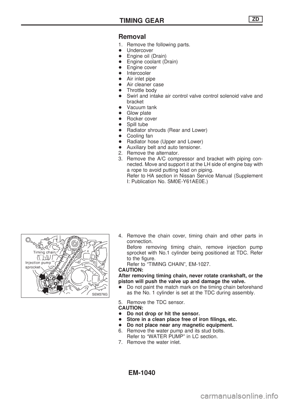
Before removing timing chain, remove injection pump
sprocket with No.1 cylinder being positioned at TDC. Refer
to the figure.
Refer to ªTIMING CHAINº, EM-1027.
CAUTION:
After removing timing chain, never rotate crankshaft, or the
piston will push the valve up and damage the valve.
+Do not paint the match mark on the timing chain beforehand
as the No. 1 cylinder is set at the TDC during assembly.
5. Remove the TDC sensor.
CAUTION:
+Do not drop or hit the sensor.
+Store in a clean place free of iron filings, etc.
+Do not place near any magnetic equipment.
6. Remove the water pump and its stud bolts.
Refer to ªWATER PUMPº in LC section.
7. Remove the water inlet.
SEM376G
TIMING GEARZD
EM-1040
Page 880 of 1033

A
A/T - Wiring diagram ............................. AT-1009
A/T control ............................................. EC-1148
A/T fluid temperature sensor ................. AT-1081
A/T mode switch .................................... AT-1095
A/T self-diagnoses ................................. AT-1028
A/T shift lock system - Wiring
diagram .............................................. AT-1117
A/T shift lock system ............................. AT-1116
A/T trouble diagnoses ........................... AT-1036
APS - Wiring diagram ........................... EC-1125
ASCD (automatic speed control
device) ............................................... EL-1110
ASCD - Wiring diagram ......................... EL-1111
AT/C - Wiring diagram .......................... EC-1150
Accelerator control system .................... FE-1007
Accelerator position sensor .................. EC-1125
Air bag disposal .................................... RS-1015
Air bag precautions ................................ GI-1002
Air bag ................................................... RS-1003
Air cleaner filter replacement ............... MA-1019
Air conditioner cut control ..................... EC-1021
Air flow meter - See Mass air flow
sensor ................................................ EC-1086
Alternator ............................................... EL-1041
Angular tightening application .............. EM-1003
Anti-lock brake system - Wiring
diagram ............................................. BR-1002
Audio ...................................................... EL-1108
Automatic speed control system - See
ASCD ................................................. EL-1110
Automatic transmission fluid
replacement ...................................... MA-1021
B
BACK/L - Wiring diagram ...................... EL-1051
BOOST - Wiring diagram ...................... EC-1204
Back-up lamp ......................................... EL-1051
Basic inspection .................................... EC-1049
Battery ................................................... EL-1035
Boring/horning cylinder block ............... EM-1075
C
CHARGE - Wiring diagram ................... EL-1040
CKPS - Wiring diagram ........................ EC-1140
CONSULT for engine ............................ EC-1038
CONSULT general information .............. GI-1003
COOL/F - Wiring diagram ..................... EC-1105
CORNER - Wiring diagram ................... EL-1054
Camshaft inspection ............................. EM-1032
Charging system .................................... EL-1040
Chassis and body maintenance ........... MA-1020
Clutch operating cylinder ....................... CL-1003
Collision diagnosis ................................ RS-1052
Combination meter ................................ EL-1073Combination switch ............................... EL-1042
Compression pressure ......................... EM-1010
Compressor mounting ........................... HA-1023
Connecting rod bearing clearance ....... EM-1078
Connecting rod bushing clearance ....... EM-1074
Connecting rod ..................................... EM-1074
Control valve (A/T) ................................ AT-1148
Converter housing installation ............... AT-1128
Coolant mixture ratio ............................ MA-1010
Coolant replacement ............................ MA-1014
Cooling fan control ................................ EC-1105
Cornering lamp ...................................... EL-1054
Crankcase emission control system -
See Positive crankcase ventilation ... EC-1022
Crankcase ventilation system - See
Positive crankcase ventilation ........... EC-1022
Crankshaft position sensor (TDC) ........ EC-1140
Crankshaft ............................................ EM-1077
Cruise control - See ASCD ................... EL-1110
Cylinder block boring ............................ EM-1020
Cylinder block ....................................... EM-1067
Cylinder head bolt tightening ................ EM-1034
Cylinder head ....................................... EM-1053
D
DEF - Wiring diagram ............................ EL-1102
DTRL - Wiring diagram ......................... EL-1044
Data link connector for Consult ............ EC-1038
Daytime light system ............................. EL-1044
Diagnosis sensor unit ........................... RS-1008
Diagnostic trouble code (DTC) for
OBD system ...................................... EC-1032
Dome light - See Interior lamp .............. EL-1067
Door mirror ............................................ BT-1007
Door trim ................................................ BT-1004
Drive belt inspection ............................. MA-1011
Drive plate runout ................................. EM-1095
Dropping resistor (A/T) .......................... AT-1086
E
ECCS-D control module .. EC-1068, 1117, 1189,
1191, 1196, 1200
ECM input/output signal ........................ EC-1068
ECTS - Wiring diagram ......................... EC-1092
EGR - Wiring diagram .......................... EC-1209
EGR volume control valve .................... EC-1207
Electrical unit ......................................... EL-1231
Electrical units location .......................... EL-1185
Electronic fuel injection pump .... EC-1119, 1153,
1159, 1165, 1171, 1177, 1180, 1215
Engine control circuit diagram .............. EC-1015
Engine control component parts
location .............................................. EC-1011
Engine control system diagram and
chart .................................................. EC-1016
ALPHABETICAL INDEX
IDX-1002
Page 909 of 1033

Checking Tightening Torque
Checking should be performed while engine is cold.
MANIFOLD BOLTS AND NUTS
Intake and exhaust manifolds:
Intake
:25-28Nzm (2.5 - 2.9 kg-m, 18 - 20 ft-lb)
Exhaust
:40-49Nzm (4.0 - 4.5 kg-m, 29 - 36 ft-lb)
Adjusting Intake and Exhaust Valve
Clearance
Refer to EM section.
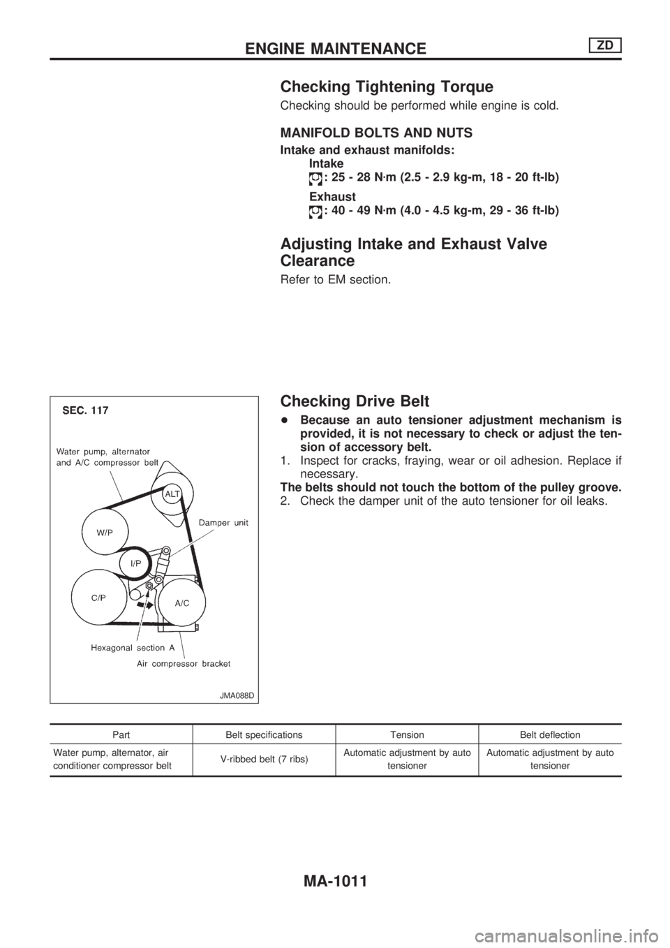
Checking Drive Belt
+Because an auto tensioner adjustment mechanism is
provided, it is not necessary to check or adjust the ten-
sion of accessory belt.
1. Inspect for cracks, fraying, wear or oil adhesion. Replace if
necessary.
The belts should not touch the bottom of the pulley groove.
2. Check the damper unit of the auto tensioner for oil leaks.
Part Belt specifications Tension Belt deflection
Water pump, alternator, air
conditioner compressor beltV-ribbed belt (7 ribs)Automatic adjustment by auto
tensionerAutomatic adjustment by auto
tensioner
JMA088D
ENGINE MAINTENANCEZD
MA-1011
Page 910 of 1033

Removal
WATER PUMP, ALTERNATOR AND AIR
CONDITIONER BELT
1. Remove radiator shroud.
2. Contract and hold the auto tensioner using the following pro-
cedure.
a. Securely hold the 19 mm (0.75 in) hexagonal portion A of
auto tensioner with a closed wrench.
+Preferably use a tool with a handhold of 500 mm (19.69 in)
or more in length.
+No bolts or nuts are required to be loosened during the
operation.
b. Turn the hexagonal portion A in the direction shown by the
arrow to contract the damper unit of the auto tensioner.
CAUTION:
+Because the tensioner has a high tension, it shall be
securely held and turned with a closed wrench.
+Because the hexagonal portion A of the tensioner is
made of aluminum and may be damaged by sudden
input, turn it slowly according to the contraction of the
damper unit.
3. Remove the belt from the alternator pulley first, and then
remove it from the other pulleys.
+If the tensioner is not held firmly, your finger may get caught
between the belt and the pulleys. Confirm the holding of the
tensioner, and then hold the belt side in the place away from
the pulleys to attach or remove the belt, paying attention to
prevent your finger from being caught.
CAUTION:
+When handling the belt, pay attention to prevent the oil
or coolant from adhering to the belt.
+Do not distort or bend the belt intensively.
Installation
+Install the belt in the reverse order of removal.
+After installation of the belt, confirm that the belt engages the
pulleys securely.
+Depending on the engagement between the belt and the idler
pulley, noise (belt noise) may be heard when the engine is
started just after installation. This noise will stop with time.
Changing Engine Oil
WARNING:
+Be careful not to burn yourself, as engine oil is hot.
+Prolonged and repeated contact with used engine oil
may cause skin cancer; try to avoid direct skin contact
with used oil. If skin contact is made, wash thoroughly
with soap or hand cleaner as soon as possible.
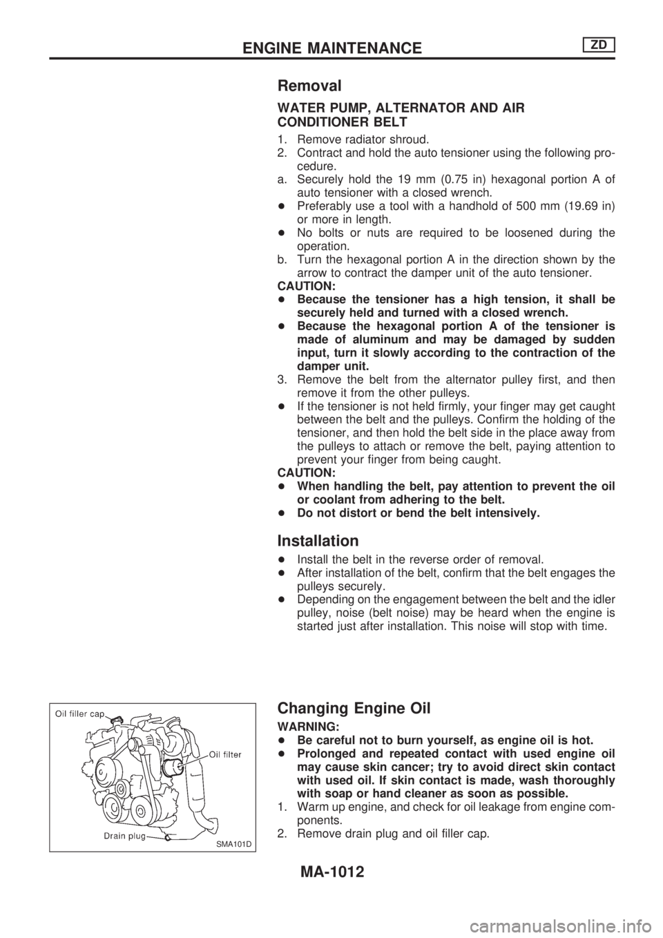
1. Warm up engine, and check for oil leakage from engine com-
ponents.
2. Remove drain plug and oil filler cap.
SMA101D
ENGINE MAINTENANCEZD
MA-1012