Page 339 of 1033

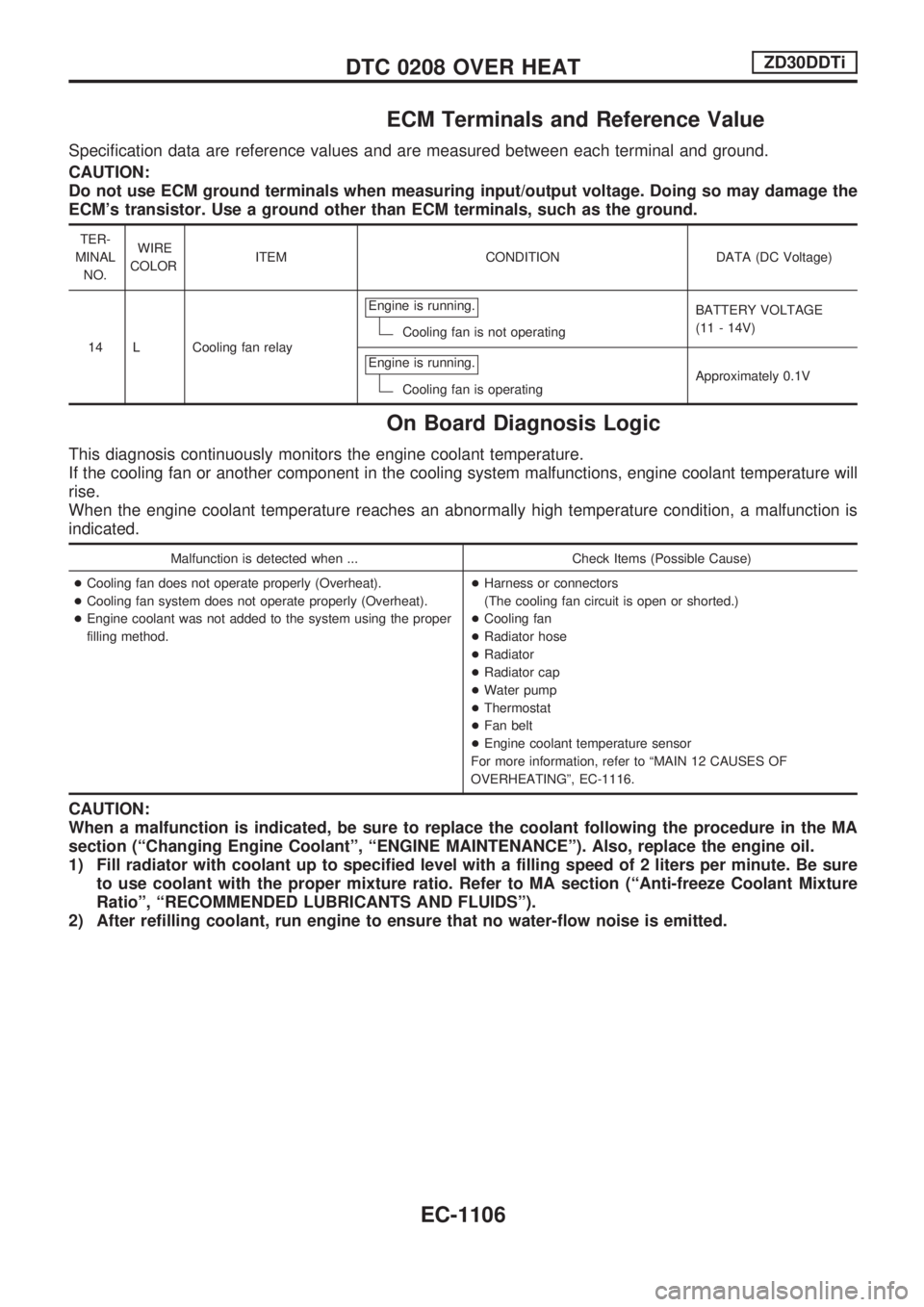
ECM Terminals and Reference Value
Specification data are reference values and are measured between each terminal and ground.
CAUTION:
Do not use ECM ground terminals when measuring input/output voltage. Doing so may damage the
ECM's transistor. Use a ground other than ECM terminals, such as the ground.
TER-
MINAL
NO.WIRE
COLORITEM CONDITION DATA (DC Voltage)
14 L Cooling fan relayEngine is running.
Cooling fan is not operatingBATTERY VOLTAGE
(11 - 14V)
Engine is running.
Cooling fan is operatingApproximately 0.1V
On Board Diagnosis Logic
This diagnosis continuously monitors the engine coolant temperature.
If the cooling fan or another component in the cooling system malfunctions, engine coolant temperature will
rise.
When the engine coolant temperature reaches an abnormally high temperature condition, a malfunction is
indicated.
Malfunction is detected when ... Check Items (Possible Cause)
+Cooling fan does not operate properly (Overheat).
+Cooling fan system does not operate properly (Overheat).
+Engine coolant was not added to the system using the proper
filling method.+Harness or connectors
(The cooling fan circuit is open or shorted.)
+Cooling fan
+Radiator hose
+Radiator
+Radiator cap
+Water pump
+Thermostat
+Fan belt
+Engine coolant temperature sensor
For more information, refer to ªMAIN 12 CAUSES OF
OVERHEATINGº, EC-1116.
CAUTION:
When a malfunction is indicated, be sure to replace the coolant following the procedure in the MA
section (ªChanging Engine Coolantº, ªENGINE MAINTENANCEº). Also, replace the engine oil.
1) Fill radiator with coolant up to specified level with a filling speed of 2 liters per minute. Be sure
to use coolant with the proper mixture ratio. Refer to MA section (ªAnti-freeze Coolant Mixture
Ratioº, ªRECOMMENDED LUBRICANTS AND FLUIDSº).
2) After refilling coolant, run engine to ensure that no water-flow noise is emitted.
DTC 0208 OVER HEATZD30DDTi
EC-1106
Page 347 of 1033
12 CHECK COOLING SYSTEM FOR LEAK
Apply pressure to the cooling system with a tester, and check if the pressure drops.
Testing pressure: 157 kPa (1.57 bar, 1.6 kg/cm
2, 23 psi)
CAUTION:
Higher than the specified pressure may cause radiator damage.
SLC754A
Pressure should not drop.
OK or NG
OKcGO TO 14.
NGcGO TO 13.
13 DETECT MALFUNCTIONING PART
Check the following for leak.
+Hose
+Radiator
+Water pump (Refer to LC section, ªWater Pumpº.)
cRepair or replace.
14 CHECK RADIATOR CAP
Apply pressure to cap with a tester and check radiator cap relief pressure.
SLC755A
Radiator cap relief pressure:
79 - 98 kPa (0.78 - 0.98 bar, 0.8 - 1.0 kg/cm2, 11 - 14 psi)
OK or NG
OKcGO TO 15.
NGcReplace radiator cap.
DTC 0208 OVER HEATZD30DDTi
Diagnostic Procedure (Cont'd)
EC-1114
Page 417 of 1033
Diagnostic Procedure
1 INSPECTION START
1. Turn ignition switch ªOFFº.
2. Perform ªAir Bleedingº, EC-1031, and ªDRAINING WATERº in MA section.
cGO TO 2.
2 PERFORM DTC CONFIRMATION PROCEDURE AGAIN
Perform ªDTC Confirmation Procedureº, EC-1182 again.
OK or NG
OKcINSPECTION END
NGcGO TO 3.
3 CHECK ELECTRONIC CONTROL FUEL INJECTION PUMP POWER SUPPLY CIRCUIT
1. Turn ignition switch ªOFFº.
2. Disconnect electronic control fuel injection pump harness connector.
SEF229Z
3. Turn ignition switch ªONº.
4. Check voltage between electronic control fuel injection pump terminal 7 and ground.
SEF438Y
OK or NG
OKcGO TO 5.
NGcGO TO 4.
DTC 0707 P7zF/INJ TIMG FBZD30DDTi
EC-1184
Page 747 of 1033

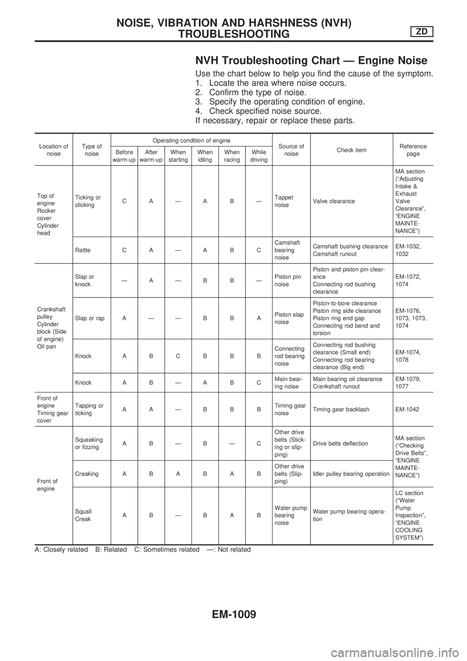
NVH Troubleshooting Chart Ð Engine Noise
Use the chart below to help you find the cause of the symptom.
1. Locate the area where noise occurs.
2. Confirm the type of noise.
3. Specify the operating condition of engine.
4. Check specified noise source.
If necessary, repair or replace these parts.
Location of
noiseType of
noiseOperating condition of engine
Source of
noiseCheck itemReference
page Before
warm-upAfter
warm-upWhen
startingWhen
idlingWhen
racingWhile
driving
Top of
engine
Rocker
cover
Cylinder
headTicking or
clickingCAÐABÐTappet
noiseValve clearanceMA section
(ªAdjusting
Intake &
Exhaust
Valve
Clearanceº,
ªENGINE
MAINTE-
NANCEº)
Rattle C A Ð A B CCamshaft
bearing
noiseCamshaft bushing clearance
Camshaft runoutEM-1032,
1032
Crankshaft
pulley
Cylinder
block (Side
of engine)
Oil panSlap or
knockÐAÐB BÐPiston pin
noisePiston and piston pin clear-
ance
Connecting rod bushing
clearanceEM-1072,
1074
Slap or rap A Ð Ð B B APiston slap
noisePiston-to-bore clearance
Piston ring side clearance
Piston ring end gap
Connecting rod bend and
torsionEM-1076,
1073, 1073,
1074
Knock A B C B B BConnecting
rod bearing
noiseConnecting rod bushing
clearance (Small end)
Connecting rod bearing
clearance (Big end)EM-1074,
1078
Knock A B Ð A B CMain bear-
ing noiseMain bearing oil clearance
Crankshaft runoutEM-1079,
1077
Front of
engine
Timing gear
coverTapping or
tickingAAÐBBBTiming gear
noiseTiming gear backlash EM-1042
Front of
engineSqueaking
or fizzingABÐBÐCOther drive
belts (Stick-
ing or slip-
ping)Drive belts deflectionMA section
(ªChecking
Drive Beltsº,
ªENGINE
MAINTE-
NANCEº) CreakingABABABOther drive
belts (Slip-
ping)Idler pulley bearing operation
Squall
CreakABÐBABWater pump
bearing
noiseWater pump bearing opera-
tionLC section
(ªWater
Pump
Inspectionº,
ªENGINE
COOLING
SYSTEMº)
A: Closely related B: Related C: Sometimes related Ð: Not related
NOISE, VIBRATION AND HARSHNESS (NVH)
TROUBLESHOOTINGZD
EM-1009
Page 765 of 1033
Removal and Installation
CAUTION:
As the internal mechanism of the idler gear must first of all,
and always, be set by a bolt when removing the timing chain
before removing the fuel injection pump and timing gear,
follow the procedures on EM-1039, ªRemoval of timing
chain after setting idler gearº, ªElectronic controlled fuel
injection pumpº.
+This chapter will deal with the summary of removing the tim-
ing chain before removing the camshaft and cylinder head.
Removal
1. Remove the following parts.
+Engine cover
+Intercooler
+Air inlet pipe
+Throttle body
+Rocker cover
+Spill tube
+Coolant (Drain)
+Radiator upper hose
+Water outlet
+Radiator shroud
+Cooling fan
+Auxilary belt
FEM003
TIMING CHAINZD
EM-1027
Page 778 of 1033

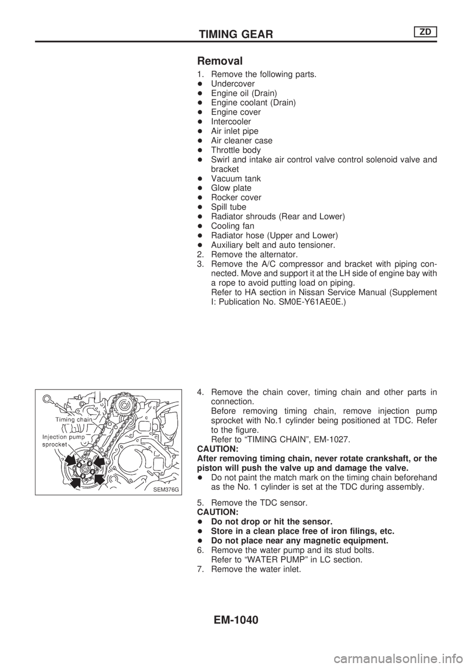
Removal
1. Remove the following parts.
+Undercover
+Engine oil (Drain)
+Engine coolant (Drain)
+Engine cover
+Intercooler
+Air inlet pipe
+Air cleaner case
+Throttle body
+Swirl and intake air control valve control solenoid valve and
bracket
+Vacuum tank
+Glow plate
+Rocker cover
+Spill tube
+Radiator shrouds (Rear and Lower)
+Cooling fan
+Radiator hose (Upper and Lower)
+Auxiliary belt and auto tensioner.
2. Remove the alternator.
3. Remove the A/C compressor and bracket with piping con-
nected. Move and support it at the LH side of engine bay with
a rope to avoid putting load on piping.
Refer to HA section in Nissan Service Manual (Supplement
I: Publication No. SM0E-Y61AE0E.)
4. Remove the chain cover, timing chain and other parts in
connection.
Before removing timing chain, remove injection pump
sprocket with No.1 cylinder being positioned at TDC. Refer
to the figure.
Refer to ªTIMING CHAINº, EM-1027.
CAUTION:
After removing timing chain, never rotate crankshaft, or the
piston will push the valve up and damage the valve.
+Do not paint the match mark on the timing chain beforehand
as the No. 1 cylinder is set at the TDC during assembly.
5. Remove the TDC sensor.
CAUTION:
+Do not drop or hit the sensor.
+Store in a clean place free of iron filings, etc.
+Do not place near any magnetic equipment.
6. Remove the water pump and its stud bolts.
Refer to ªWATER PUMPº in LC section.
7. Remove the water inlet.
SEM376G
TIMING GEARZD
EM-1040
Page 787 of 1033

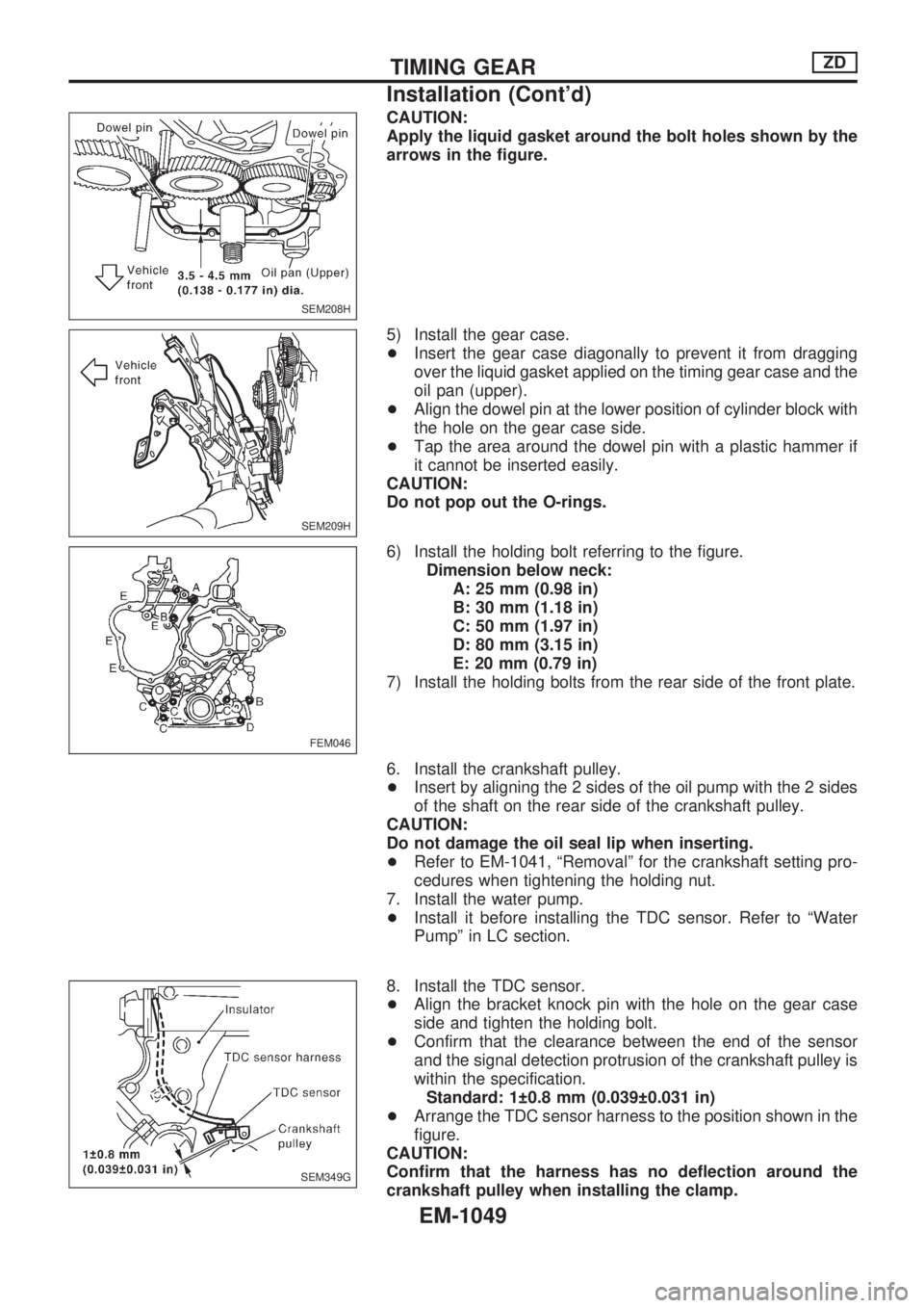
CAUTION:
Apply the liquid gasket around the bolt holes shown by the
arrows in the figure.
5) Install the gear case.
+Insert the gear case diagonally to prevent it from dragging
over the liquid gasket applied on the timing gear case and the
oil pan (upper).
+Align the dowel pin at the lower position of cylinder block with
the hole on the gear case side.
+Tap the area around the dowel pin with a plastic hammer if
it cannot be inserted easily.
CAUTION:
Do not pop out the O-rings.
6) Install the holding bolt referring to the figure.
Dimension below neck:
A: 25 mm (0.98 in)
B: 30 mm (1.18 in)
C: 50 mm (1.97 in)
D: 80 mm (3.15 in)
E: 20 mm (0.79 in)
7) Install the holding bolts from the rear side of the front plate.
6. Install the crankshaft pulley.
+Insert by aligning the 2 sides of the oil pump with the 2 sides
of the shaft on the rear side of the crankshaft pulley.
CAUTION:
Do not damage the oil seal lip when inserting.
+Refer to EM-1041, ªRemovalº for the crankshaft setting pro-
cedures when tightening the holding nut.
7. Install the water pump.
+Install it before installing the TDC sensor. Refer to ªWater
Pumpº in LC section.
8. Install the TDC sensor.
+Align the bracket knock pin with the hole on the gear case
side and tighten the holding bolt.
+Confirm that the clearance between the end of the sensor
and the signal detection protrusion of the crankshaft pulley is
within the specification.
Standard: 1 0.8 mm (0.039 0.031 in)
+Arrange the TDC sensor harness to the position shown in the
figure.
CAUTION:
Confirm that the harness has no deflection around the
crankshaft pulley when installing the clamp.
SEM208H
SEM209H
FEM046
SEM349G
TIMING GEARZD
Installation (Cont'd)
EM-1049
Page 791 of 1033
Removal and Installation
Removal
1. Remove the following. (Refer to corresponding chapter for
detailed auxiliary work.)
+Drain coolant
+Rocker cover
+Injection tube
+Spill tube
+High pressure injection nozzle assembly
+Timing chain
+Camshaft
+Catalytic converter
+Turbocharger assembly
+Exhaust manifold
2. Remove mounting bolts of the gear case and water pump as
shown by arrows in the figure.
3. Remove oil return pipe from the rear side of cylinder head.
4. Remove intake manifold.
SEM359G
FEM054
CYLINDER HEADZD
EM-1053