2000 NISSAN PATROL automatic transmission
[x] Cancel search: automatic transmissionPage 1 of 1033
Edition: February 2000
Release: February 2000 (01)
Publication No.: SM0E-Y61AE0E
Reference No.: 7711346024GENERAL INFORMATIONGI
MAINTENANCEMA
ENGINE MECHANICALEM
ENGINE LUBRICATION &
COOLING SYSTEMSLC
ENGINE CONTROL SYSTEMEC
ACCELERATOR CONTROL,
FUEL & EXHAUST SYSTEMFE
CLUTCHCL
MANUAL TRANSMISSIONMT
AUTOMATIC TRANSMISSIONAT
TRANSFERTF
PROPELLER SHAFT &
DIFFERENTIAL CARRIERPD
FRONT AXLE & FRONT SUSPENSIONFA
REAR AXLE & REAR SUSPENSIONRA
BRAKE SYSTEMBR
STEERING SYSTEMST
RESTRAINT SYSTEMRS
BODY & TRIMBT
HEATER & AIR CONDITIONERHA
ELECTRICAL SYSTEMEL
ALPHABETICAL INDEXIDX
PATROL GR
MODEL Y61 SERIES
NISSAN EUROPE S.A.S.
2000 NISSAN EUROPE S.A.S.
Produced in The Netherlands
Not to be reproduced in whole or in part
without the prior written permission of
Nissan Europe S.A.S., Paris, France.
QUICK REFERENCE INDEX
Page 3 of 1033

AUTOMATIC TRANSMISSION
SECTION
AT
CONTENTS
PREPARATION AND PRECAUTIONS............... 1003
Special Service Tools ...................................... 1003
Supplemental Restraint System (SRS) ªAIR
BAGº and ªSEAT BELT PRE-TENSIONERº ... 1004
Precautions ...................................................... 1004
Service Notice or Precautions ......................... 1006
OVERALL SYSTEM............................................ 1007
A/T Electrical Parts Location ........................... 1007
Circuit Diagram ................................................ 1008
Wiring Diagram Ð A/T Ð ................................ 1009
Cross-sectional View ....................................... 1022
Hydraulic Control Circuits ................................ 1023
Shift Mechanism .............................................. 1024
Control System ................................................ 1026
ON BOARD DIAGNOSTIC SYSTEM
DESCRIPTION..................................................... 1028
Self-diagnosis................................................... 1028
Diagnosis by CONSULT-II ............................... 1034
TROUBLE DIAGNOSIS Ð Introduction............ 1036
Introduction ...................................................... 1036
Diagnostic Worksheet ...................................... 1037
Work Flow ........................................................ 1040
TROUBLE DIAGNOSIS Ð Basic Inspection.... 1041
A/T Fluid Check ............................................... 1041
Stall Test .......................................................... 1041
Line Pressure Test........................................... 1044
Road Test ........................................................ 1046
TROUBLE DIAGNOSIS Ð General
Description.......................................................... 1057
Symptom Chart ................................................ 1057
TCM Terminals and Reference Value ............. 1060
TROUBLE DIAGNOSIS FOR VHCL SPEED
SENzA/T................................................................ 1064Vehicle Speed SensorzA/T (Revolution
sensor) ............................................................. 1064
TROUBLE DIAGNOSIS FOR VHCL SPEED
SENzMTR.............................................................. 1066
Vehicle Speed SensorzzMTR ............................ 1066
TROUBLE DIAGNOSIS FOR THROTTLE POSI
SEN...................................................................... 1068
Accelerator Position Sensor ............................ 1068
TROUBLE DIAGNOSIS FOR SHIFT
SOLENOID/V A.................................................... 1070
Shift Solenoid Valve A ..................................... 1070
TROUBLE DIAGNOSIS FOR SHIFT
SOLENOID/V B.................................................... 1072
Shift Solenoid Valve B ..................................... 1072
TROUBLE DIAGNOSIS FOR OVERRUN
CLUTCH S/V........................................................ 1074
Overrun Clutch Solenoid Valve ....................... 1074
TROUBLE DIAGNOSIS FOR T/C CLUTCH
SOL/V................................................................... 1076
Torque Converter Clutch Solenoid Valve ........ 1076
TROUBLE DIAGNOSIS FOR BATT/FLUID
TEMP SEN........................................................... 1079
A/T Fluid Temperature Sensor and TCM
Power Source .................................................. 1079
TROUBLE DIAGNOSIS FOR ENGINE SPEED
SIG....................................................................... 1082
Engine Speed Signal ....................................... 1082
TROUBLE DIAGNOSIS FOR LINE PRESSURE
S/V........................................................................ 1084
Line Pressure Solenoid Valve ......................... 1084
TROUBLE DIAGNOSIS FOR CONTROL UNIT
(RAM), CONTROL UNIT (ROM)......................... 1087
Description ....................................................... 1087
AT
Page 26 of 1033
Shift Mechanism
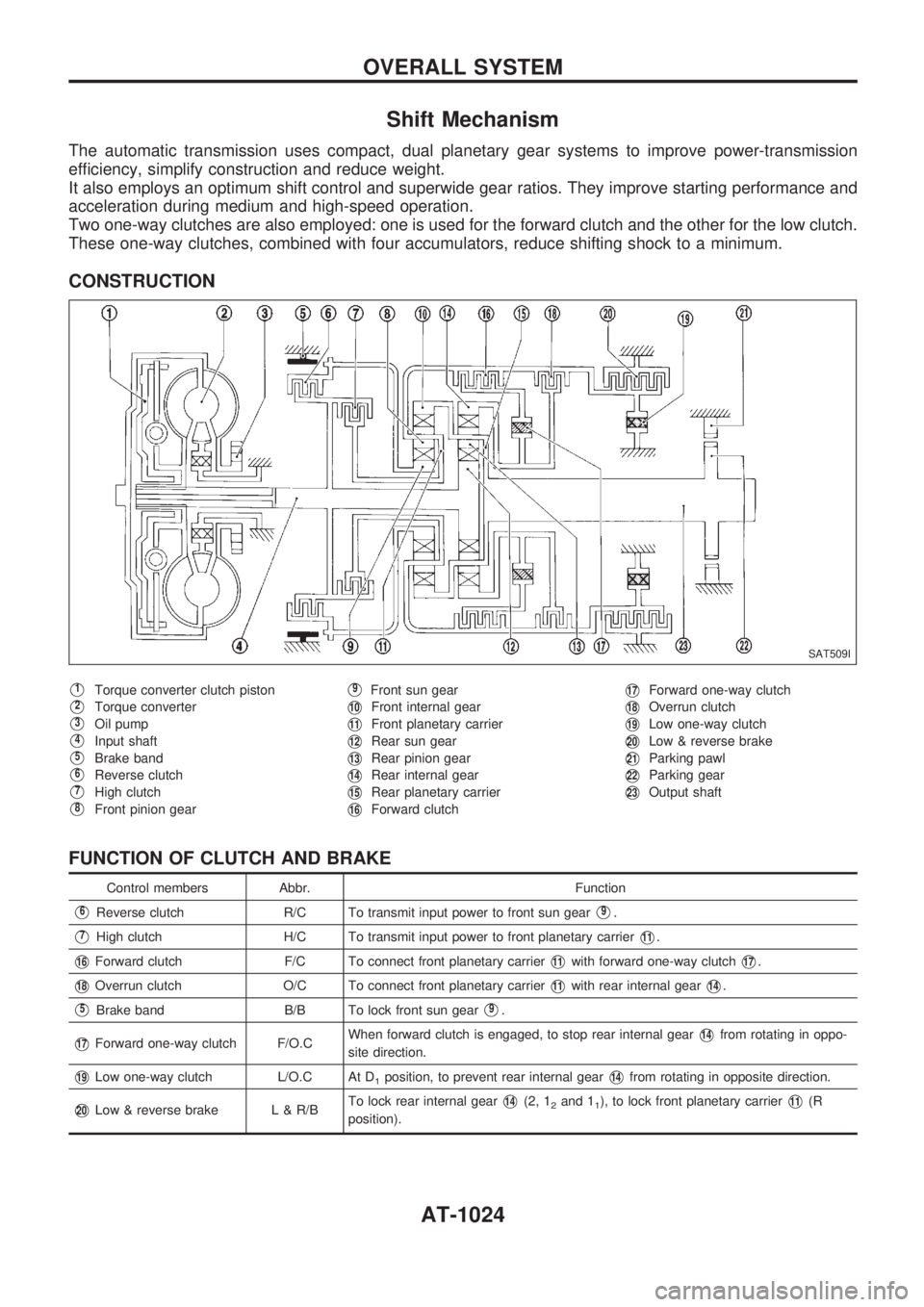
The automatic transmission uses compact, dual planetary gear systems to improve power-transmission
efficiency, simplify construction and reduce weight.
It also employs an optimum shift control and superwide gear ratios. They improve starting performance and
acceleration during medium and high-speed operation.
Two one-way clutches are also employed: one is used for the forward clutch and the other for the low clutch.
These one-way clutches, combined with four accumulators, reduce shifting shock to a minimum.
CONSTRUCTION
V1Torque converter clutch piston
V2Torque converter
V3Oil pump
V4Input shaft
V5Brake band
V6Reverse clutch
V7High clutch
V8Front pinion gear
V9Front sun gear
V10Front internal gear
V11Front planetary carrier
V12Rear sun gear
V13Rear pinion gear
V14Rear internal gear
V15Rear planetary carrier
V16Forward clutch
V17Forward one-way clutch
V18Overrun clutch
V19Low one-way clutch
V20Low & reverse brake
V21Parking pawl
V22Parking gear
V23Output shaft
FUNCTION OF CLUTCH AND BRAKE
Control members Abbr. Function
V6Reverse clutch R/C To transmit input power to front sun gearV9.
V7High clutch H/C To transmit input power to front planetary carrierV11.
V16Forward clutch F/C To connect front planetary carrierV11with forward one-way clutchV17.
V18Overrun clutch O/C To connect front planetary carrierV11with rear internal gearV14.
V5Brake band B/B To lock front sun gearV9.
V17Forward one-way clutch F/O.CWhen forward clutch is engaged, to stop rear internal gearV14from rotating in oppo-
site direction.
V19Low one-way clutch L/O.C At D1position, to prevent rear internal gearV14from rotating in opposite direction.
V20Low & reverse brake L & R/BTo lock rear internal gearV14(2, 12and 11), to lock front planetary carrierV11(R
position).
SAT509I
OVERALL SYSTEM
AT-1024
Page 27 of 1033
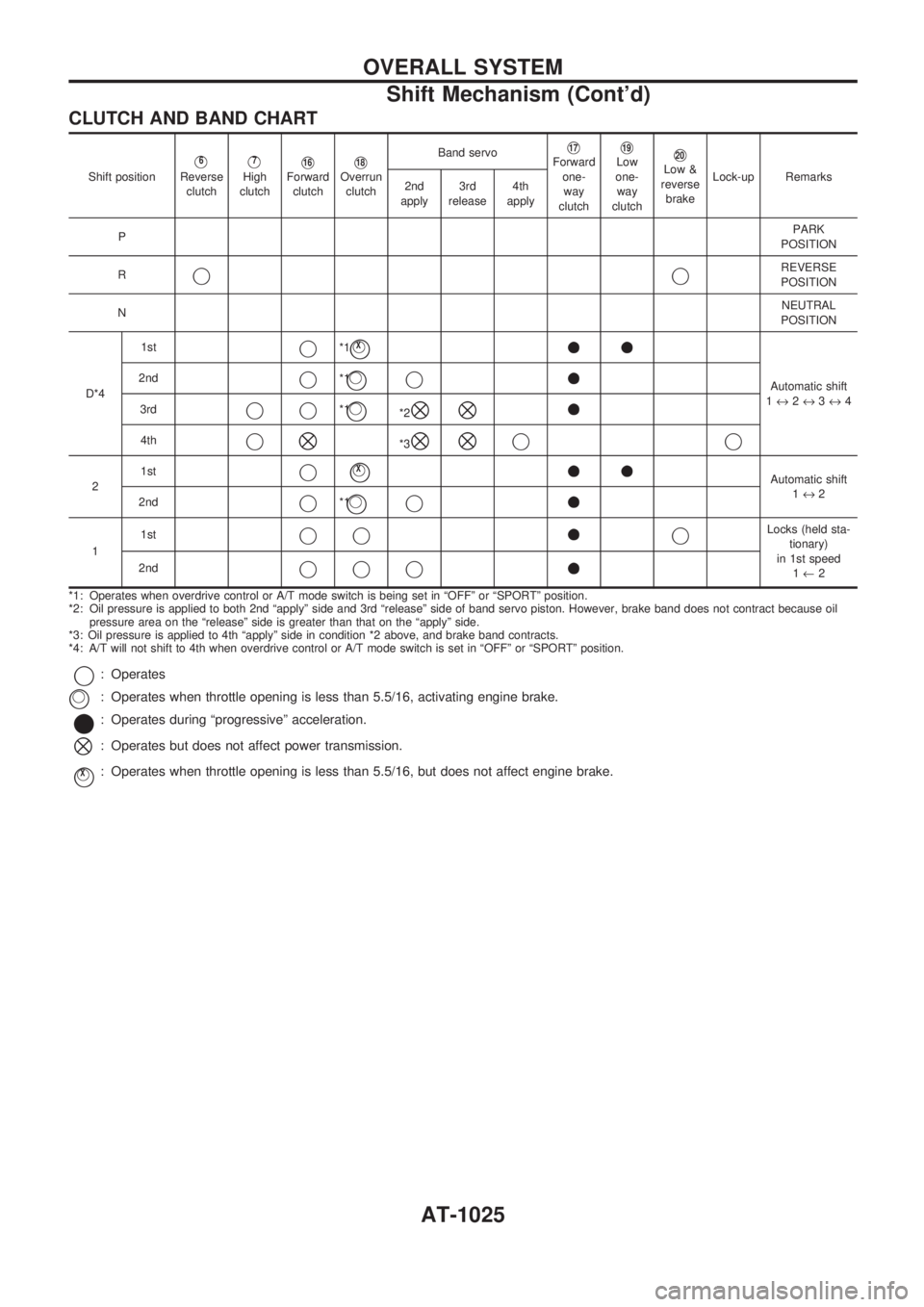
CLUTCH AND BAND CHART
Shift positionV6
Reverse
clutchV7
High
clutchV16Forward
clutchV18Overrun
clutchBand servo
V17Forward
one-
way
clutchV19Low
one-
way
clutchV20Low &
reverse
brakeLock-up Remarks
2nd
apply3rd
release4th
apply
PPARK
POSITION
R
jjREVERSE
POSITION
NNEUTRAL
POSITION
D*41st
j*1jVX++
Automatic shift
1«2«3«4 2ndj*1jVj+
3rdjj*1jV*2^^+
4thj^*3^^jj
21stjjVX++Automatic shift
1«2
2nd
j*1jVj+
11stjj+jLocks (held sta-
tionary)
in 1st speed
1¬2 2nd
jjj+
*1: Operates when overdrive control or A/T mode switch is being set in ªOFFº or ªSPORTº position.
*2: Oil pressure is applied to both 2nd ªapplyº side and 3rd ªreleaseº side of band servo piston. However, brake band does not contract because oil
pressure area on the ªreleaseº side is greater than that on the ªapplyº side.
*3: Oil pressure is applied to 4th ªapplyº side in condition *2 above, and brake band contracts.
*4: A/T will not shift to 4th when overdrive control or A/T mode switch is set in ªOFFº or ªSPORTº position.
j: Operates
: Operates when throttle opening is less than 5.5/16, activating engine brake.
*: Operates during ªprogressiveº acceleration.
^: Operates but does not affect power transmission.
jVX: Operates when throttle opening is less than 5.5/16, but does not affect engine brake.
jV
OVERALL SYSTEM
Shift Mechanism (Cont'd)
AT-1025
Page 28 of 1033
Control System
OUTLINE
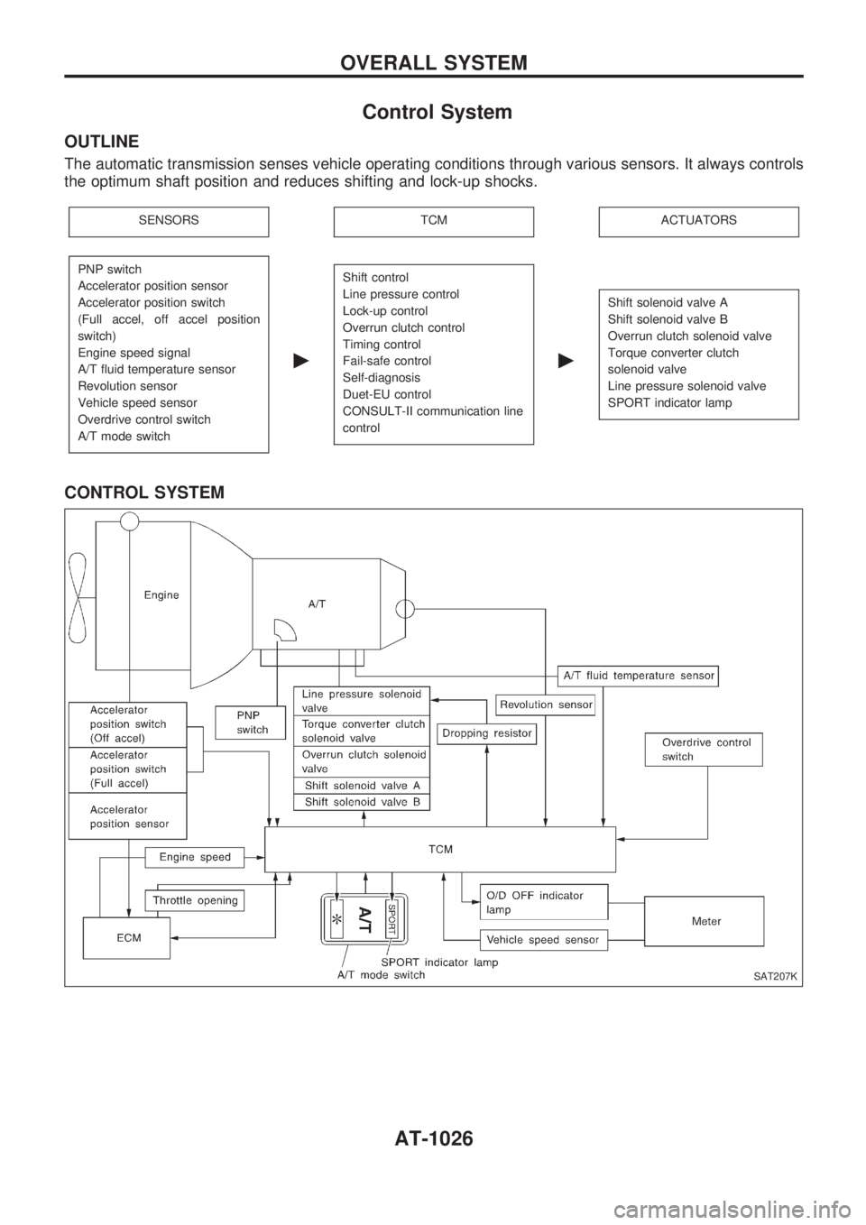
The automatic transmission senses vehicle operating conditions through various sensors. It always controls
the optimum shaft position and reduces shifting and lock-up shocks.
SENSORSTCMACTUATORS
PNP switch
Accelerator position sensor
Accelerator position switch
(Full accel, off accel position
switch)
Engine speed signal
A/T fluid temperature sensor
Revolution sensor
Vehicle speed sensor
Overdrive control switch
A/T mode switch
c
Shift control
Line pressure control
Lock-up control
Overrun clutch control
Timing control
Fail-safe control
Self-diagnosis
Duet-EU control
CONSULT-II communication line
control
c
Shift solenoid valve A
Shift solenoid valve B
Overrun clutch solenoid valve
Torque converter clutch
solenoid valve
Line pressure solenoid valve
SPORT indicator lamp
CONTROL SYSTEM
SAT207K
OVERALL SYSTEM
AT-1026
Page 208 of 1033
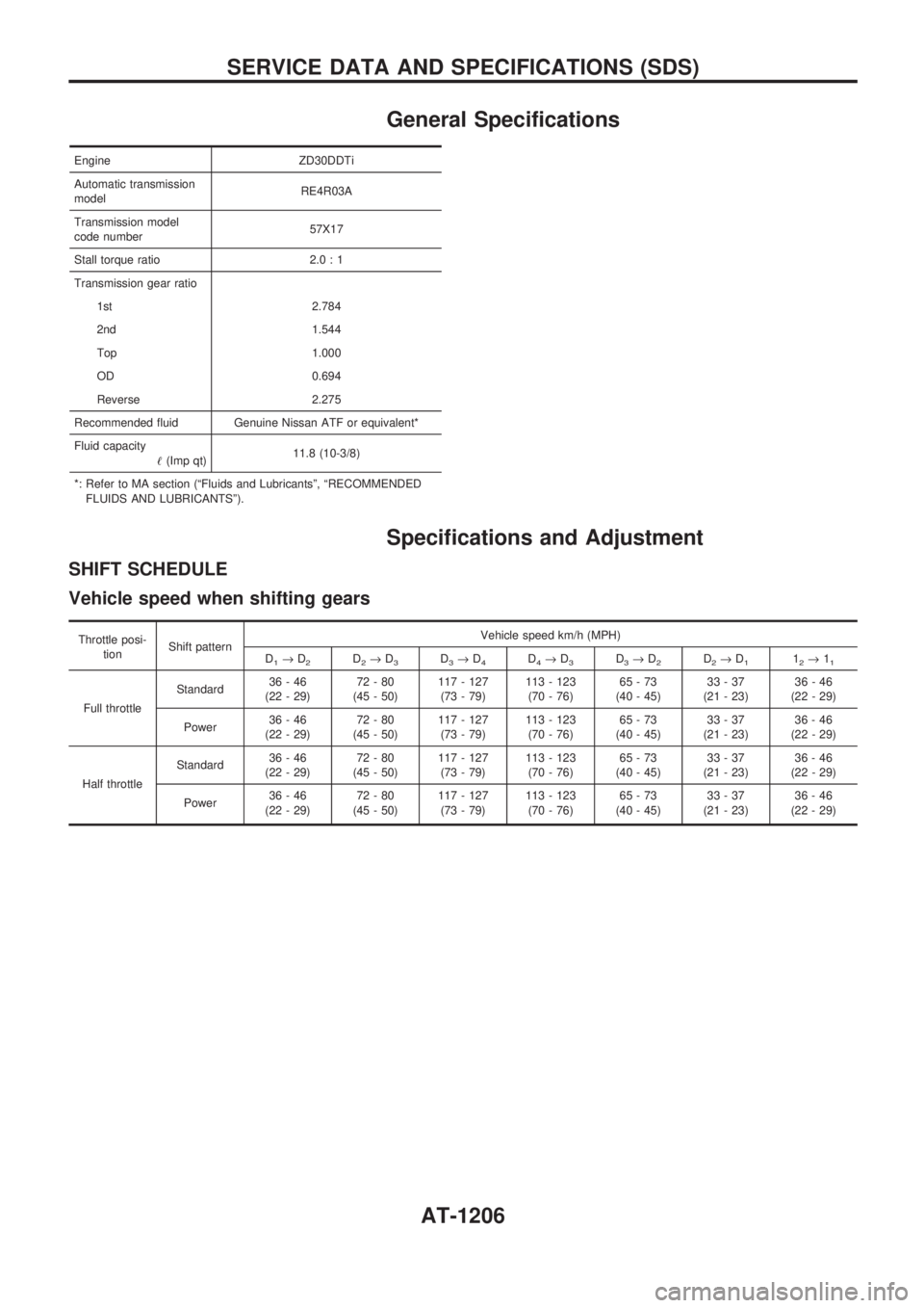
General Specifications
Engine ZD30DDTi
Automatic transmission
modelRE4R03A
Transmission model
code number57X17
Stall torque ratio 2.0 : 1
Transmission gear ratio
1st 2.784
2nd 1.544
Top 1.000
OD 0.694
Reverse 2.275
Recommended fluid Genuine Nissan ATF or equivalent*
Fluid capacity
!(Imp qt)11.8 (10-3/8)
*: Refer to MA section (ªFluids and Lubricantsº, ªRECOMMENDED
FLUIDS AND LUBRICANTSº).
Specifications and Adjustment
SHIFT SCHEDULE
Vehicle speed when shifting gears
Throttle posi-
tionShift patternVehicle speed km/h (MPH)
D
1®D2D2®D3D3®D4D4®D3D3®D2D2®D112®11
Full throttleStandard36-46
(22 - 29)72-80
(45 - 50)117 - 127
(73 - 79)113 - 123
(70 - 76)65-73
(40 - 45)33-37
(21 - 23)36-46
(22 - 29)
Power36-46
(22 - 29)72-80
(45 - 50)117 - 127
(73 - 79)113 - 123
(70 - 76)65-73
(40 - 45)33-37
(21 - 23)36-46
(22 - 29)
Half throttleStandard36-46
(22 - 29)72-80
(45 - 50)117 - 127
(73 - 79)113 - 123
(70 - 76)65-73
(40 - 45)33-37
(21 - 23)36-46
(22 - 29)
Power36-46
(22 - 29)72-80
(45 - 50)117 - 127
(73 - 79)113 - 123
(70 - 76)65-73
(40 - 45)33-37
(21 - 23)36-46
(22 - 29)
SERVICE DATA AND SPECIFICATIONS (SDS)
AT-1206
Page 851 of 1033
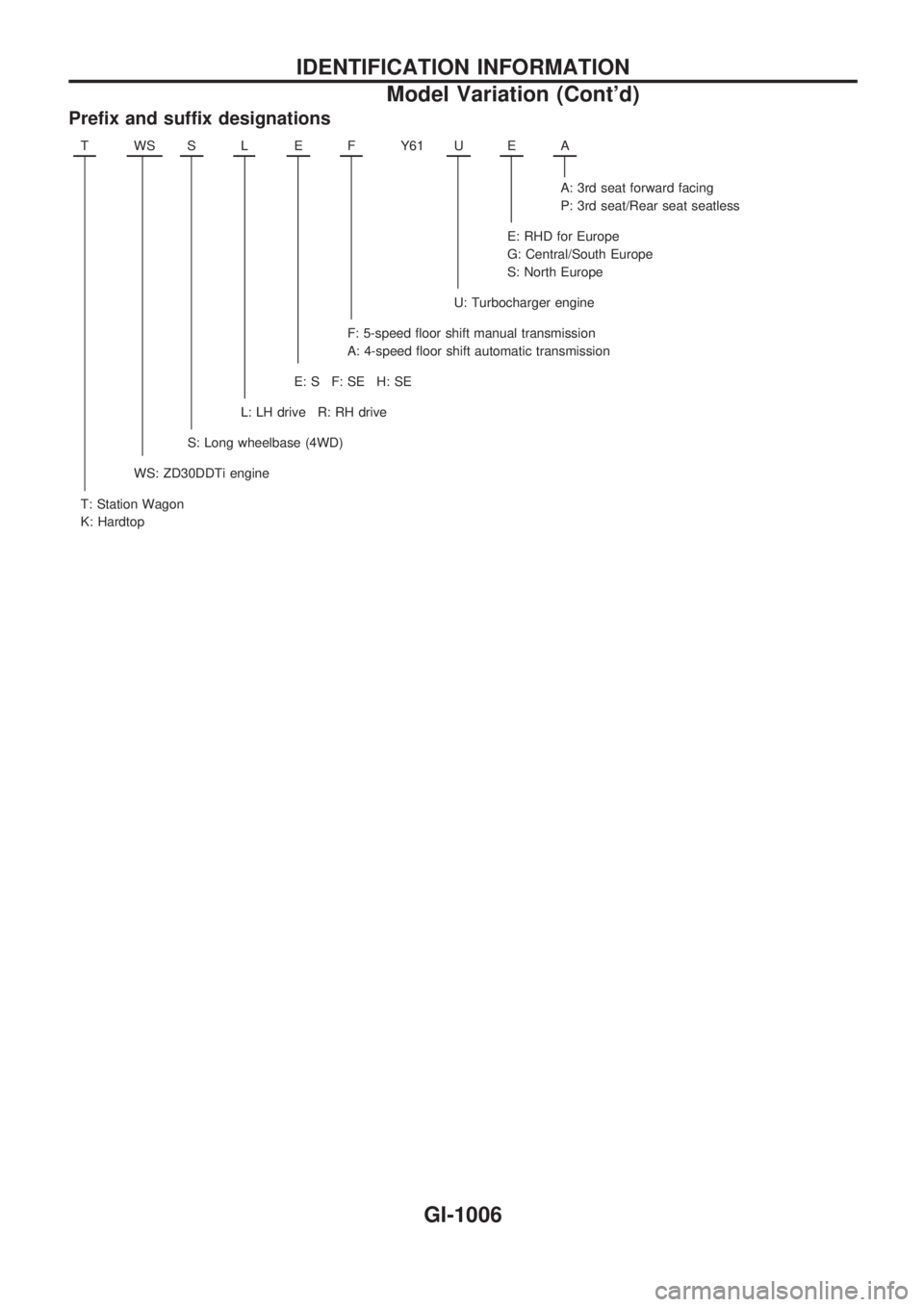
Prefix and suffix designations
TWSSLEFY61 UEA
A: 3rd seat forward facing
P: 3rd seat/Rear seat seatless
E: RHD for Europe
G: Central/South Europe
S: North Europe
U: Turbocharger engine
F: 5-speed floor shift manual transmission
A: 4-speed floor shift automatic transmission
E:SF:SEH:SE
L: LH drive R: RH drive
S: Long wheelbase (4WD)
WS: ZD30DDTi engine
T: Station Wagon
K: Hardtop
IDENTIFICATION INFORMATION
Model Variation (Cont'd)
GI-1006
Page 880 of 1033
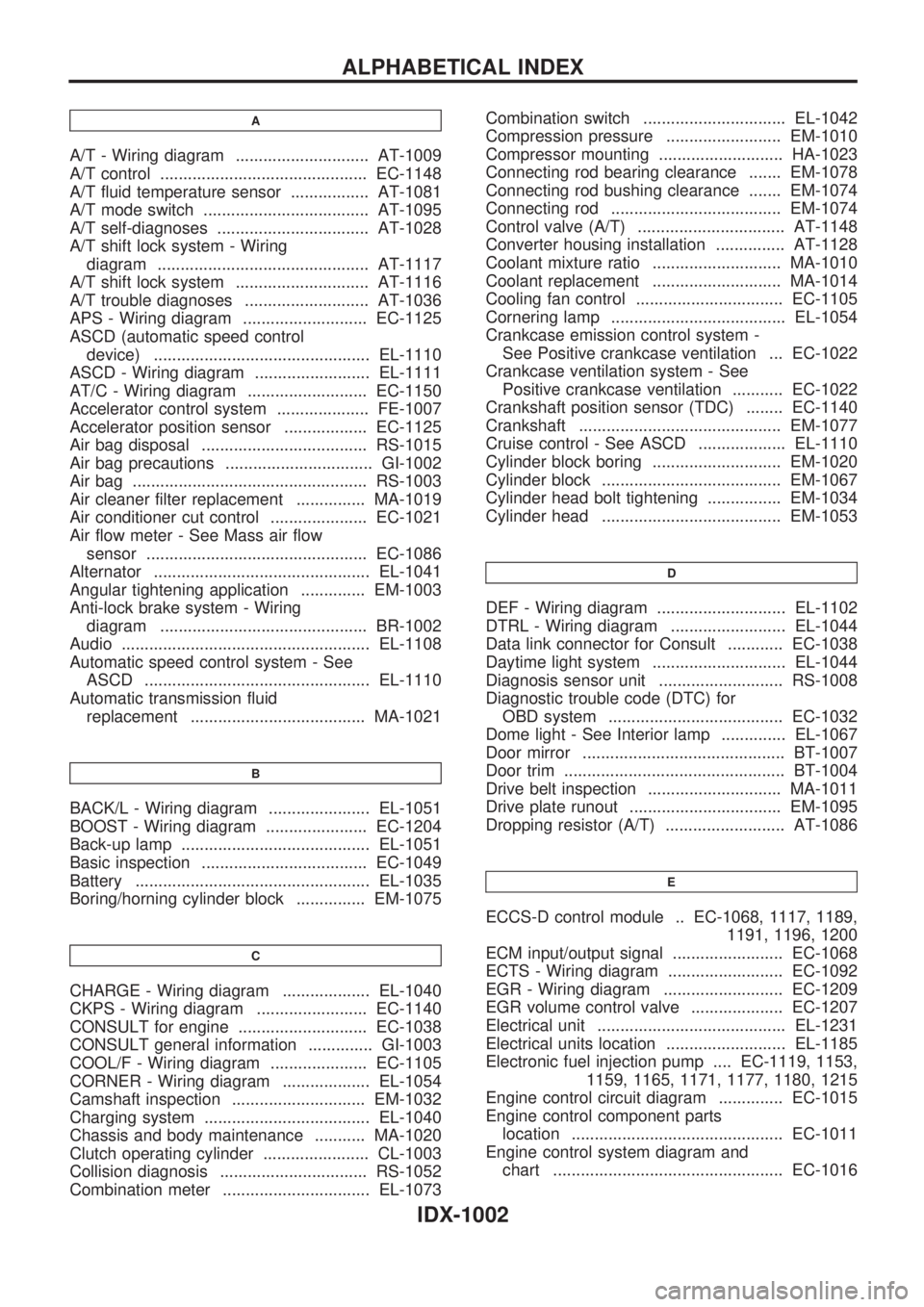
A
A/T - Wiring diagram ............................. AT-1009
A/T control ............................................. EC-1148
A/T fluid temperature sensor ................. AT-1081
A/T mode switch .................................... AT-1095
A/T self-diagnoses ................................. AT-1028
A/T shift lock system - Wiring
diagram .............................................. AT-1117
A/T shift lock system ............................. AT-1116
A/T trouble diagnoses ........................... AT-1036
APS - Wiring diagram ........................... EC-1125
ASCD (automatic speed control
device) ............................................... EL-1110
ASCD - Wiring diagram ......................... EL-1111
AT/C - Wiring diagram .......................... EC-1150
Accelerator control system .................... FE-1007
Accelerator position sensor .................. EC-1125
Air bag disposal .................................... RS-1015
Air bag precautions ................................ GI-1002
Air bag ................................................... RS-1003
Air cleaner filter replacement ............... MA-1019
Air conditioner cut control ..................... EC-1021
Air flow meter - See Mass air flow
sensor ................................................ EC-1086
Alternator ............................................... EL-1041
Angular tightening application .............. EM-1003
Anti-lock brake system - Wiring
diagram ............................................. BR-1002
Audio ...................................................... EL-1108
Automatic speed control system - See
ASCD ................................................. EL-1110
Automatic transmission fluid
replacement ...................................... MA-1021
B
BACK/L - Wiring diagram ...................... EL-1051
BOOST - Wiring diagram ...................... EC-1204
Back-up lamp ......................................... EL-1051
Basic inspection .................................... EC-1049
Battery ................................................... EL-1035
Boring/horning cylinder block ............... EM-1075
C
CHARGE - Wiring diagram ................... EL-1040
CKPS - Wiring diagram ........................ EC-1140
CONSULT for engine ............................ EC-1038
CONSULT general information .............. GI-1003
COOL/F - Wiring diagram ..................... EC-1105
CORNER - Wiring diagram ................... EL-1054
Camshaft inspection ............................. EM-1032
Charging system .................................... EL-1040
Chassis and body maintenance ........... MA-1020
Clutch operating cylinder ....................... CL-1003
Collision diagnosis ................................ RS-1052
Combination meter ................................ EL-1073Combination switch ............................... EL-1042
Compression pressure ......................... EM-1010
Compressor mounting ........................... HA-1023
Connecting rod bearing clearance ....... EM-1078
Connecting rod bushing clearance ....... EM-1074
Connecting rod ..................................... EM-1074
Control valve (A/T) ................................ AT-1148
Converter housing installation ............... AT-1128
Coolant mixture ratio ............................ MA-1010
Coolant replacement ............................ MA-1014
Cooling fan control ................................ EC-1105
Cornering lamp ...................................... EL-1054
Crankcase emission control system -
See Positive crankcase ventilation ... EC-1022
Crankcase ventilation system - See
Positive crankcase ventilation ........... EC-1022
Crankshaft position sensor (TDC) ........ EC-1140
Crankshaft ............................................ EM-1077
Cruise control - See ASCD ................... EL-1110
Cylinder block boring ............................ EM-1020
Cylinder block ....................................... EM-1067
Cylinder head bolt tightening ................ EM-1034
Cylinder head ....................................... EM-1053
D
DEF - Wiring diagram ............................ EL-1102
DTRL - Wiring diagram ......................... EL-1044
Data link connector for Consult ............ EC-1038
Daytime light system ............................. EL-1044
Diagnosis sensor unit ........................... RS-1008
Diagnostic trouble code (DTC) for
OBD system ...................................... EC-1032
Dome light - See Interior lamp .............. EL-1067
Door mirror ............................................ BT-1007
Door trim ................................................ BT-1004
Drive belt inspection ............................. MA-1011
Drive plate runout ................................. EM-1095
Dropping resistor (A/T) .......................... AT-1086
E
ECCS-D control module .. EC-1068, 1117, 1189,
1191, 1196, 1200
ECM input/output signal ........................ EC-1068
ECTS - Wiring diagram ......................... EC-1092
EGR - Wiring diagram .......................... EC-1209
EGR volume control valve .................... EC-1207
Electrical unit ......................................... EL-1231
Electrical units location .......................... EL-1185
Electronic fuel injection pump .... EC-1119, 1153,
1159, 1165, 1171, 1177, 1180, 1215
Engine control circuit diagram .............. EC-1015
Engine control component parts
location .............................................. EC-1011
Engine control system diagram and
chart .................................................. EC-1016
ALPHABETICAL INDEX
IDX-1002