2000 NISSAN PATROL weight
[x] Cancel search: weightPage 6 of 1033
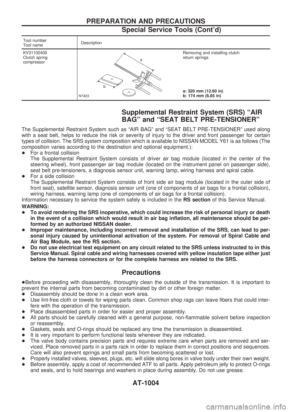
Tool number
Tool nameDescription
KV31102400
Clutch spring
compressor
NT423
Removing and installing clutch
return springs
a: 320 mm (12.60 in)
b: 174 mm (6.85 in)
Supplemental Restraint System (SRS) ªAIR
BAGº and ªSEAT BELT PRE-TENSIONERº
The Supplemental Restraint System such as ªAIR BAGº and ªSEAT BELT PRE-TENSIONERº used along
with a seat belt, helps to reduce the risk or severity of injury to the driver and front passenger for certain
types of collision. The SRS system composition which is available to NISSAN MODEL Y61 is as follows (The
composition varies according to the destination and optional equipment.):
+For a frontal collision
The Supplemental Restraint System consists of driver air bag module (located in the center of the
steering wheel), front passenger air bag module (located on the instrument panel on passenger side),
seat belt pre-tensioners, a diagnosis sensor unit, warning lamp, wiring harness and spiral cable.
+For a side collision
The Supplemental Restraint System consists of front side air bag module (located in the outer side of
front seat), satellite sensor, diagnosis sensor unit (one of components of air bags for a frontal collision),
wiring harness, warning lamp (one of components of air bags for a frontal collision).
Information necessary to service the system safely is included in theRS sectionof this Service Manual.
WARNING:
+To avoid rendering the SRS inoperative, which could increase the risk of personal injury or death
in the event of a collision which would result in air bag inflation, all maintenance should be per-
formed by an authorized NISSAN dealer.
+Improper maintenance, including incorrect removal and installation of the SRS, can lead to per-
sonal injury caused by unintentional activation of the system. For removal of Spiral Cable and
Air Bag Module, see the RS section.
+Do not use electrical test equipment on any circuit related to the SRS unless instructed to in this
Service Manual. Spiral cable and wiring harnesses covered with yellow insulation tape either just
before the harness connectors or for the complete harness are related to the SRS.
Precautions
+Before proceeding with disassembly, thoroughly clean the outside of the transmission. It is important to
prevent the internal parts from becoming contaminated by dirt or other foreign matter.
+Disassembly should be done in a clean work area.
+Use lint-free cloth or towels for wiping parts clean. Common shop rags can leave fibers that could inter-
fere with the operation of the transmission.
+Place disassembled parts in order for easier and proper assembly.
+All parts should be carefully cleaned with a general purpose, non-flammable solvent before inspection
or reassembly.
+Gaskets, seals and O-rings should be replaced any time the transmission is disassembled.
+It is very important to perform functional tests whenever they are indicated.
+The valve body contains precision parts and requires extreme care when parts are removed and ser-
viced. Place removed parts in a parts rack in order to replace them in correct positions and sequences.
Care will also prevent springs and small parts from becoming scattered or lost.
+Properly installed valves, sleeves, plugs, etc. will slide along bores in valve body under their own weight.
+Before assembly, apply a coat of recommended ATF to all parts. Apply petroleum jelly to protect O-rings
and seals, and to hold bearings and washers in place during assembly. Do not use grease.
PREPARATION AND PRECAUTIONS
Special Service Tools (Cont'd)
AT-1004
Page 26 of 1033
Shift Mechanism
The automatic transmission uses compact, dual planetary gear systems to improve power-transmission
efficiency, simplify construction and reduce weight.
It also employs an optimum shift control and superwide gear ratios. They improve starting performance and
acceleration during medium and high-speed operation.
Two one-way clutches are also employed: one is used for the forward clutch and the other for the low clutch.
These one-way clutches, combined with four accumulators, reduce shifting shock to a minimum.
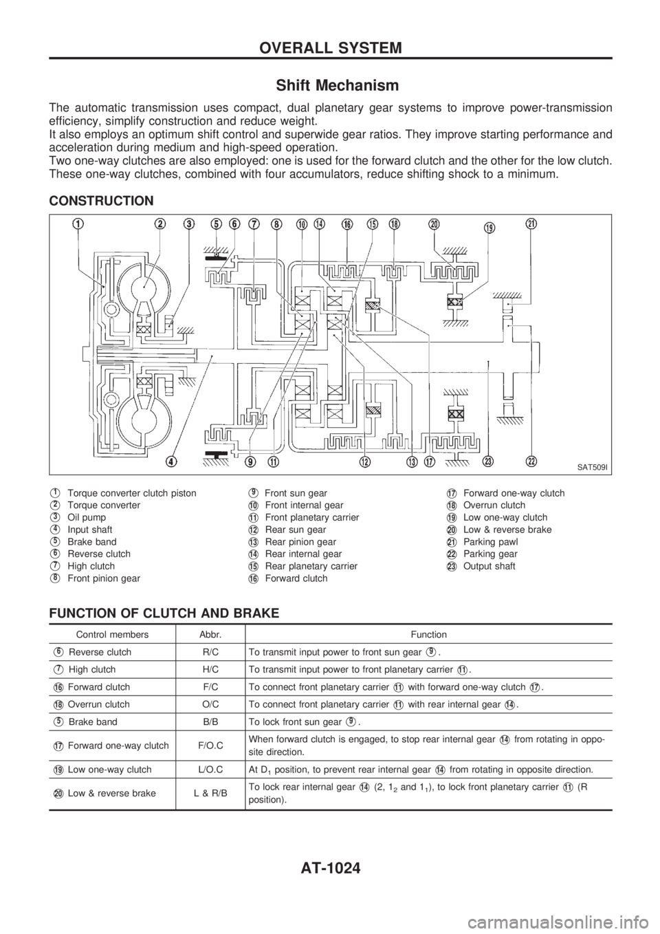
CONSTRUCTION
V1Torque converter clutch piston
V2Torque converter
V3Oil pump
V4Input shaft
V5Brake band
V6Reverse clutch
V7High clutch
V8Front pinion gear
V9Front sun gear
V10Front internal gear
V11Front planetary carrier
V12Rear sun gear
V13Rear pinion gear
V14Rear internal gear
V15Rear planetary carrier
V16Forward clutch
V17Forward one-way clutch
V18Overrun clutch
V19Low one-way clutch
V20Low & reverse brake
V21Parking pawl
V22Parking gear
V23Output shaft
FUNCTION OF CLUTCH AND BRAKE
Control members Abbr. Function
V6Reverse clutch R/C To transmit input power to front sun gearV9.
V7High clutch H/C To transmit input power to front planetary carrierV11.
V16Forward clutch F/C To connect front planetary carrierV11with forward one-way clutchV17.
V18Overrun clutch O/C To connect front planetary carrierV11with rear internal gearV14.
V5Brake band B/B To lock front sun gearV9.
V17Forward one-way clutch F/O.CWhen forward clutch is engaged, to stop rear internal gearV14from rotating in oppo-
site direction.
V19Low one-way clutch L/O.C At D1position, to prevent rear internal gearV14from rotating in opposite direction.
V20Low & reverse brake L & R/BTo lock rear internal gearV14(2, 12and 11), to lock front planetary carrierV11(R
position).
SAT509I
OVERALL SYSTEM
AT-1024
Page 813 of 1033
+New connecting rods are classified into 8 weight classes at
factory. The same class connecting rods are used on a
engine.
Weight grade symbol Weight class g (oz)
H 1,261 - 1,264 (44.5 - 44.6)
I 1,264 - 1,267 (44.6 - 44.7)
K 1,267 - 1,270 (44.7 - 44.8)
L 1,270 - 1,273 (44.8 - 44.9)
M 1,273 - 1,276 (44.9 - 45.0)
O 1,276 - 1,279 (45.0 - 45.1)
P 1,279 - 1,282 (45.1 - 45.2)
S 1,282 - 1,285 (45.2 - 45.3)
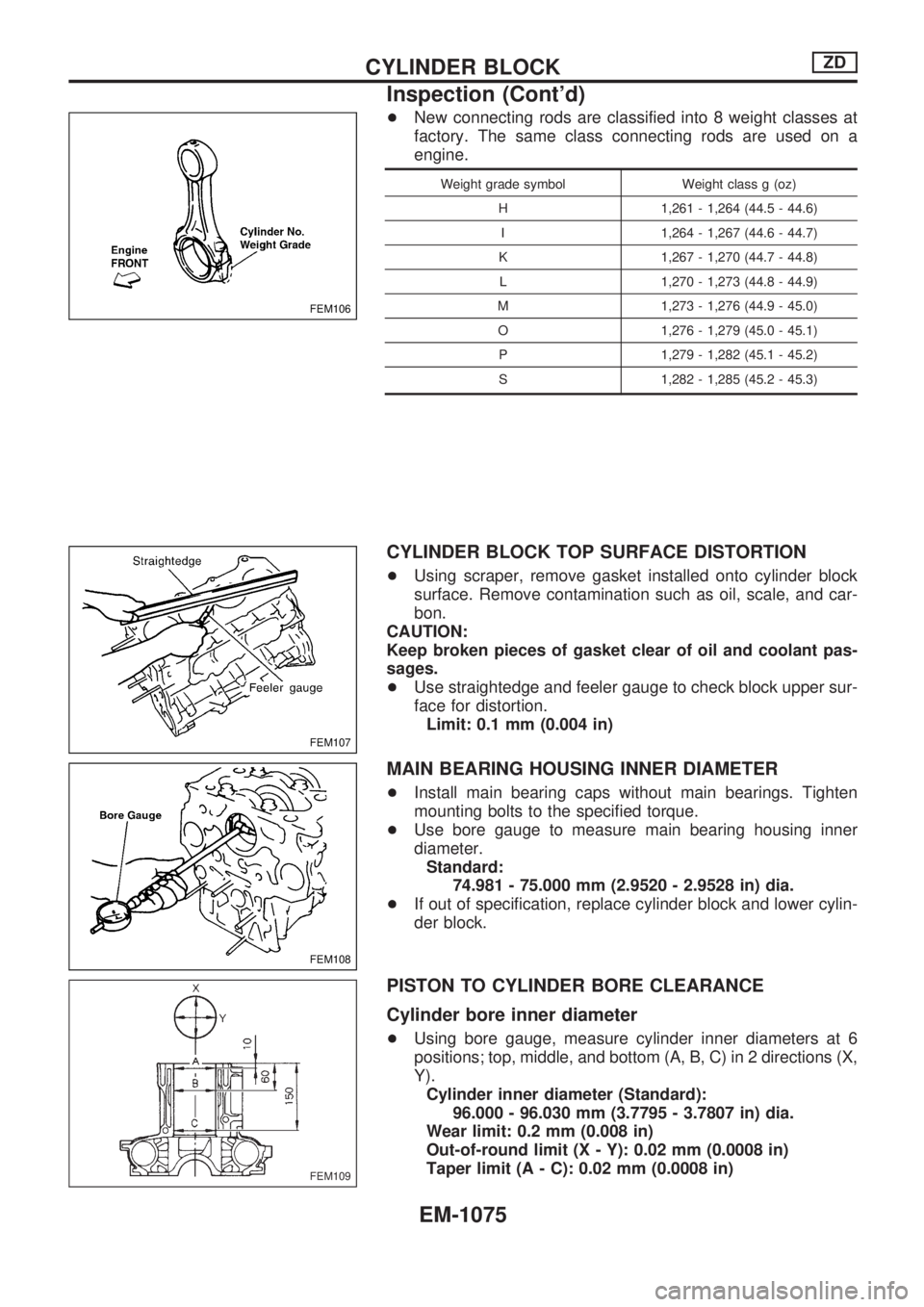
CYLINDER BLOCK TOP SURFACE DISTORTION
+Using scraper, remove gasket installed onto cylinder block
surface. Remove contamination such as oil, scale, and car-
bon.
CAUTION:
Keep broken pieces of gasket clear of oil and coolant pas-
sages.
+Use straightedge and feeler gauge to check block upper sur-
face for distortion.
Limit: 0.1 mm (0.004 in)
MAIN BEARING HOUSING INNER DIAMETER
+Install main bearing caps without main bearings. Tighten
mounting bolts to the specified torque.
+Use bore gauge to measure main bearing housing inner
diameter.
Standard:
74.981 - 75.000 mm (2.9520 - 2.9528 in) dia.
+If out of specification, replace cylinder block and lower cylin-
der block.
PISTON TO CYLINDER BORE CLEARANCE
Cylinder bore inner diameter
+Using bore gauge, measure cylinder inner diameters at 6
positions; top, middle, and bottom (A, B, C) in 2 directions (X,
Y).
Cylinder inner diameter (Standard):
96.000 - 96.030 mm (3.7795 - 3.7807 in) dia.
Wear limit: 0.2 mm (0.008 in)
Out-of-round limit (X - Y): 0.02 mm (0.0008 in)
Taper limit (A - C): 0.02 mm (0.0008 in)
FEM106
FEM107
FEM108
FEM109
CYLINDER BLOCKZD
Inspection (Cont'd)
EM-1075
Page 815 of 1033
Selective combination chart
Unit: mm (in)
j: Preferable combination
n: Allowable combination
X: NG combinationPiston grade
12
95.950 - 95.960
(3.7776 - 3.7779)95.960 - 95.970
(3.7779 - 3.7783)
Cylinder
bore grade
(Cylinder
block bore
inner
diameter)196.000 - 96.010
(3.7795 - 3.7799)jX
296.010 - 96.020
(3.7799 - 3.7803)nj
396.020 - 96.030
(3.7803 - 3.7807)nj
+Piston grade 3 (95.980/95.970) is applicable at factory only.
+New pistons are classified into 4 weight classes at factory.
The same class pistons are used on a engine.
Weight grade symbol Weight class g (oz)
E 600 - 605 (21.2 - 21.3)
F 605 - 610 (21.3 - 21.5)
G 610 - 615 (21.5 - 21.7)
H 615 - 620 (21.7 - 21.9)
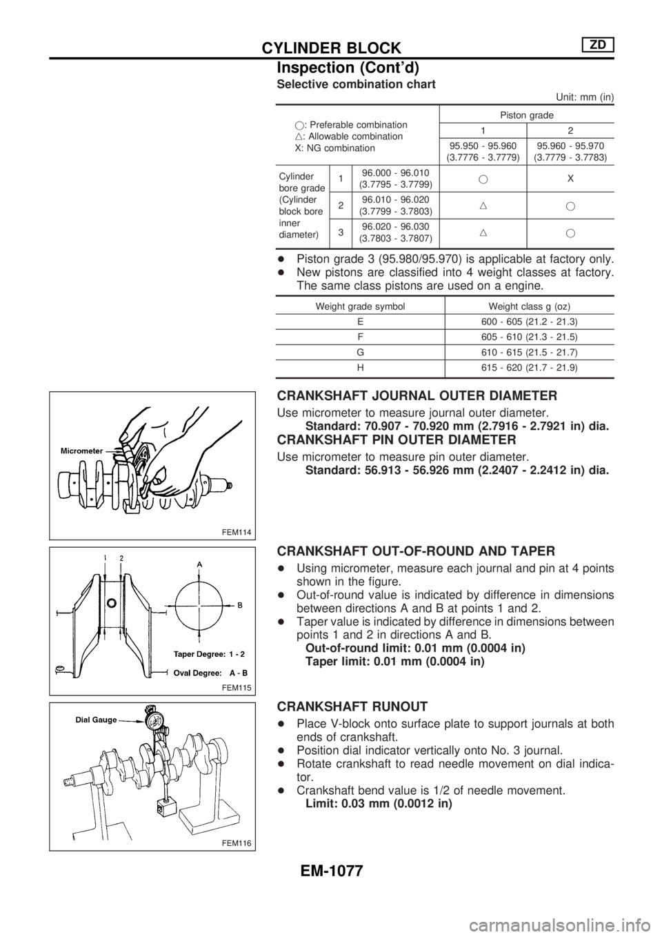
CRANKSHAFT JOURNAL OUTER DIAMETER
Use micrometer to measure journal outer diameter.
Standard: 70.907 - 70.920 mm (2.7916 - 2.7921 in) dia.
CRANKSHAFT PIN OUTER DIAMETER
Use micrometer to measure pin outer diameter.
Standard: 56.913 - 56.926 mm (2.2407 - 2.2412 in) dia.
CRANKSHAFT OUT-OF-ROUND AND TAPER
+Using micrometer, measure each journal and pin at 4 points
shown in the figure.
+Out-of-round value is indicated by difference in dimensions
between directions A and B at points 1 and 2.
+Taper value is indicated by difference in dimensions between
points 1 and 2 in directions A and B.
Out-of-round limit: 0.01 mm (0.0004 in)
Taper limit: 0.01 mm (0.0004 in)
CRANKSHAFT RUNOUT
+Place V-block onto surface plate to support journals at both
ends of crankshaft.
+Position dial indicator vertically onto No. 3 journal.
+Rotate crankshaft to read needle movement on dial indica-
tor.
+Crankshaft bend value is 1/2 of needle movement.
Limit: 0.03 mm (0.0012 in)
FEM114
FEM115
FEM116
CYLINDER BLOCKZD
Inspection (Cont'd)
EM-1077
Page 888 of 1033
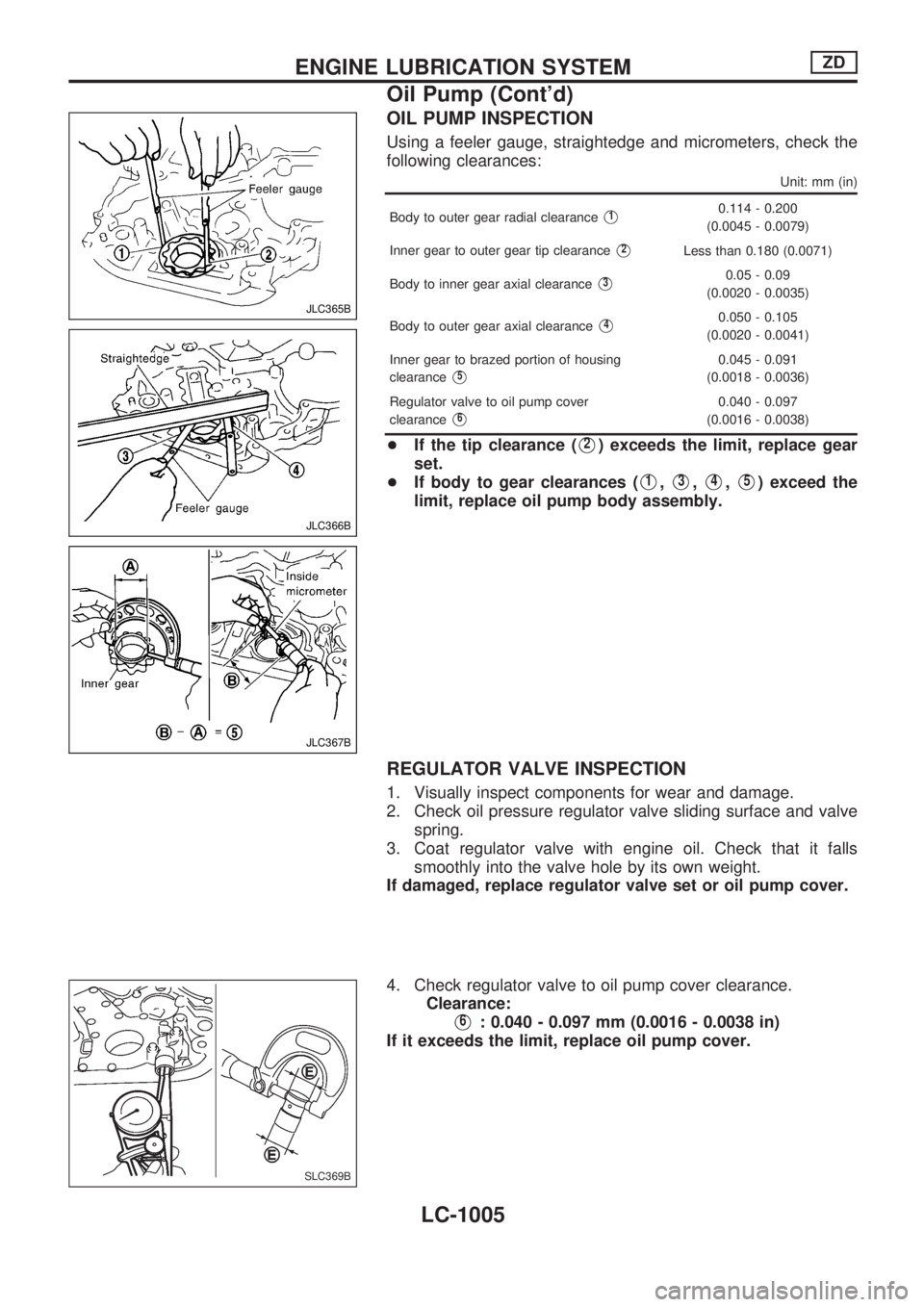
OIL PUMP INSPECTION
Using a feeler gauge, straightedge and micrometers, check the
following clearances:
Unit: mm (in)
Body to outer gear radial clearanceV10.114 - 0.200
(0.0045 - 0.0079)
Inner gear to outer gear tip clearance
V2Less than 0.180 (0.0071)
Body to inner gear axial clearance
V30.05 - 0.09
(0.0020 - 0.0035)
Body to outer gear axial clearance
V40.050 - 0.105
(0.0020 - 0.0041)
Inner gear to brazed portion of housing
clearance
V50.045 - 0.091
(0.0018 - 0.0036)
Regulator valve to oil pump cover
clearance
V60.040 - 0.097
(0.0016 - 0.0038)
+If the tip clearance (V2) exceeds the limit, replace gear
set.
+If body to gear clearances (
V1,V3,V4,V5) exceed the
limit, replace oil pump body assembly.
REGULATOR VALVE INSPECTION
1. Visually inspect components for wear and damage.
2. Check oil pressure regulator valve sliding surface and valve
spring.
3. Coat regulator valve with engine oil. Check that it falls
smoothly into the valve hole by its own weight.
If damaged, replace regulator valve set or oil pump cover.
4. Check regulator valve to oil pump cover clearance.
Clearance:
V6: 0.040 - 0.097 mm (0.0016 - 0.0038 in)
If it exceeds the limit, replace oil pump cover.
JLC365B
JLC366B
JLC367B
SLC369B
ENGINE LUBRICATION SYSTEMZD
Oil Pump (Cont'd)
LC-1005