2000 NISSAN PATROL stop start
[x] Cancel search: stop startPage 273 of 1033
![NISSAN PATROL 2000 Electronic Repair Manual Monitored item
[Unit]ECM
input
signalsMain
signalsDescription Remarks
VHCL SPEED SE
[km/h] or [mph]jj+The vehicle speed computed from the
vehicle speed sensor signal is displayed.
FUEL TEMP SEN
[ÉC]](/manual-img/5/57367/w960_57367-272.png "NISSAN PATROL 2000 Electronic Repair Manual Monitored item
[Unit]ECM
input
signalsMain
signalsDescription Remarks
VHCL SPEED SE
[km/h] or [mph]jj+The vehicle speed computed from the
vehicle speed sensor signal is displayed.
FUEL TEMP SEN
[ÉC]")
Monitored item
[Unit]ECM
input
signalsMain
signalsDescription Remarks
VHCL SPEED SE
[km/h] or [mph]jj+The vehicle speed computed from the
vehicle speed sensor signal is displayed.
FUEL TEMP SEN
[ÉC] or [ÉF]jj+The fuel temperature (sent from elec-
tronic control fuel injection pump) is dis-
played.
ACCEL POS SEN [V]
jj+The accelerator position sensor signal
voltage is displayed.
FULL ACCEL SW
[ON/OFF]jj+Indicates [ON/OFF] condition from the
accelerator position switch signal.
ACCEL SW (FC)
[OPEN/CLOSE]jj+Indicates [OPEN/CLOSE] condition from
the accelerator switch (FC) signal.
OFF ACCEL SW
[ON/OFF]jj+Indicates [ON/OFF] condition from the
accelerator position switch signal.
SPILL/V [ÉCA]
j+The control position of spill valve (sent
from electronic control fuel injection
pump) is displayed.
BATTERY VOLT [V]
jj+The power supply voltage of ECM is dis-
played.
P/N POSI SW
[ON/OFF]jj+Indicates [ON/OFF] condition from the
park/neutral position switch signal.
START SIGNAL
[ON/OFF]jj+Indicates [ON/OFF] condition from the
starter signal.+After starting the engine, [OFF] is dis-
played regardless of the starter signal.
AIR COND SIG
[ON/OFF]jj+Indicates [ON/OFF] condition of the air
conditioner switch as determined by the
air conditioner signal.
BRAKE SW [ON/OFF]
jj+Indicates [ON/OFF] condition from the
stop lamp switch signal.
IGN SW
[ON/OFF]jj+Indicates [ON/OFF] condition from igni-
tion switch signal.
WARM UP SW
[ON/OFF]j+Indicates [ON/OFF] condition from the
heat up switch signal.
MAS AIR/FL SE [V]
jj+The signal voltage of the mass air flow
sensor is displayed.+When the engine is stopped, a certain
value is indicated.
DECELER F/CUT
[ON/OFF]j+The [ON/OFF] condition from decelera-
tion fuel cut signal (sent from electronic
control fuel injection pump) is displayed.
INJ TIMG C/V [%]
j+The duty ratio of fuel injection timing
control valve (sent from electronic con-
trol fuel injection pump) is displayed.
AIR COND RLY
[ON/OFF]j+Indicates the control condition of the air
conditioner relay (determined by ECM
according to the input signals).
GLOW RLY [ON/OFF]
j+The glow relay control condition (deter-
mined by ECM according to the input
signal) is displayed.
ON BOARD DIAGNOSTIC SYSTEM DESCRIPTIONZD30DDTi
CONSULT-II (Cont'd)
EC-1040
Page 294 of 1033
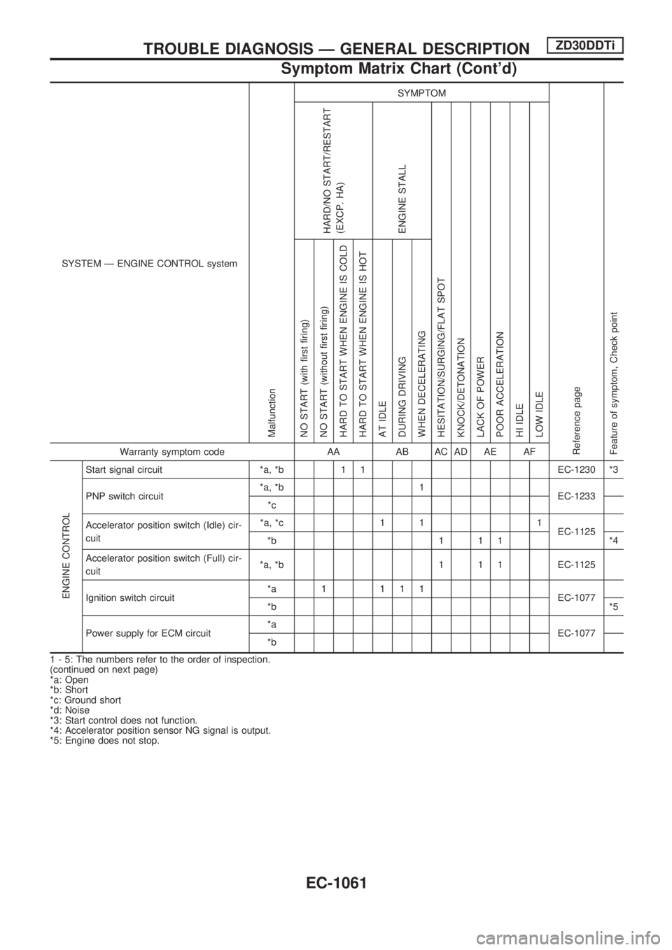
SYSTEM Ð ENGINE CONTROL system
Malfunction
SYMPTOM
Reference page
Feature of symptom, Check pointHARD/NO START/RESTART
(EXCP. HA)
ENGINE STALL
HESITATION/SURGING/FLAT SPOT
KNOCK/DETONATION
LACK OF POWER
POOR ACCELERATION
HI IDLE
LOW IDLE NO START (with first firing)
NO START (without first firing)
HARD TO START WHEN ENGINE IS COLD
HARD TO START WHEN ENGINE IS HOT
AT IDLE
DURING DRIVING
WHEN DECELERATINGWarranty symptom code AA AB AC AD AE AF
ENGINE CONTROL
Start signal circuit *a, *b 1 1 EC-1230 *3
PNP switch circuit*a, *b 1
EC-1233
*c
Accelerator position switch (Idle) cir-
cuit*a, *c 1 1 1
EC-1125
*b 1 1 1 *4
Accelerator position switch (Full) cir-
cuit*a, *b 1 1 1 EC-1125
Ignition switch circuit*a 1 111
EC-1077
*b*5
Power supply for ECM circuit*a
EC-1077
*b
1 - 5: The numbers refer to the order of inspection.
(continued on next page)
*a: Open
*b: Short
*c: Ground short
*d: Noise
*3: Start control does not function.
*4: Accelerator position sensor NG signal is output.
*5: Engine does not stop.
TROUBLE DIAGNOSIS Ð GENERAL DESCRIPTIONZD30DDTi
Symptom Matrix Chart (Cont'd)
EC-1061
Page 295 of 1033
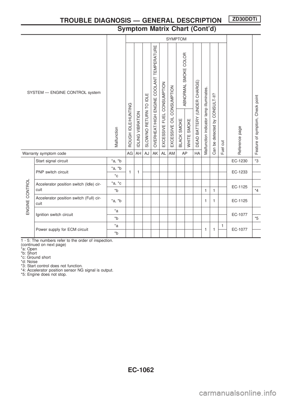
SYSTEM Ð ENGINE CONTROL system
Malfunction
SYMPTOM
Reference page
Feature of symptom, Check pointROUGH IDLE/HUNTING
IDLING VIBRATION
SLOW/NO RETURN TO IDLE
OVERHEAT/HIGH ENGINE COOLANT TEMPERATURE
EXCESSIVE FUEL CONSUMPTION
EXCESSIVE OIL CONSUMPTION
ABNORMAL SMOKE COLOR
DEAD BATTERY (UNDER CHARGE)
Malfunction indicator lamp illuminates.
Can be detected by CONSULT-II?
Fuel cutBLACK SMOKE
WHITE SMOKEWarranty symptom code AG AH AJ AK AL AM AP HA
ENGINE CONTROL
Start signal circuit *a, *b EC-1230 *3
PNP switch circuit*a, *b
1 1 EC-1233
*c
Accelerator position switch (Idle) cir-
cuit*a, *c
EC-1125
*b 1 1 *4
Accelerator position switch (Full) cir-
cuit*a, *b 1 1 EC-1125
Ignition switch circuit*a
EC-1077
*b*5
Power supply for ECM circuit*a
111
EC-1077
*b
1 - 5: The numbers refer to the order of inspection.
(continued on next page)
*a: Open
*b: Short
*c: Ground short
*d: Noise
*3: Start control does not function.
*4: Accelerator position sensor NG signal is output.
*5: Engine does not stop.
TROUBLE DIAGNOSIS Ð GENERAL DESCRIPTIONZD30DDTi
Symptom Matrix Chart (Cont'd)
EC-1062
Page 296 of 1033
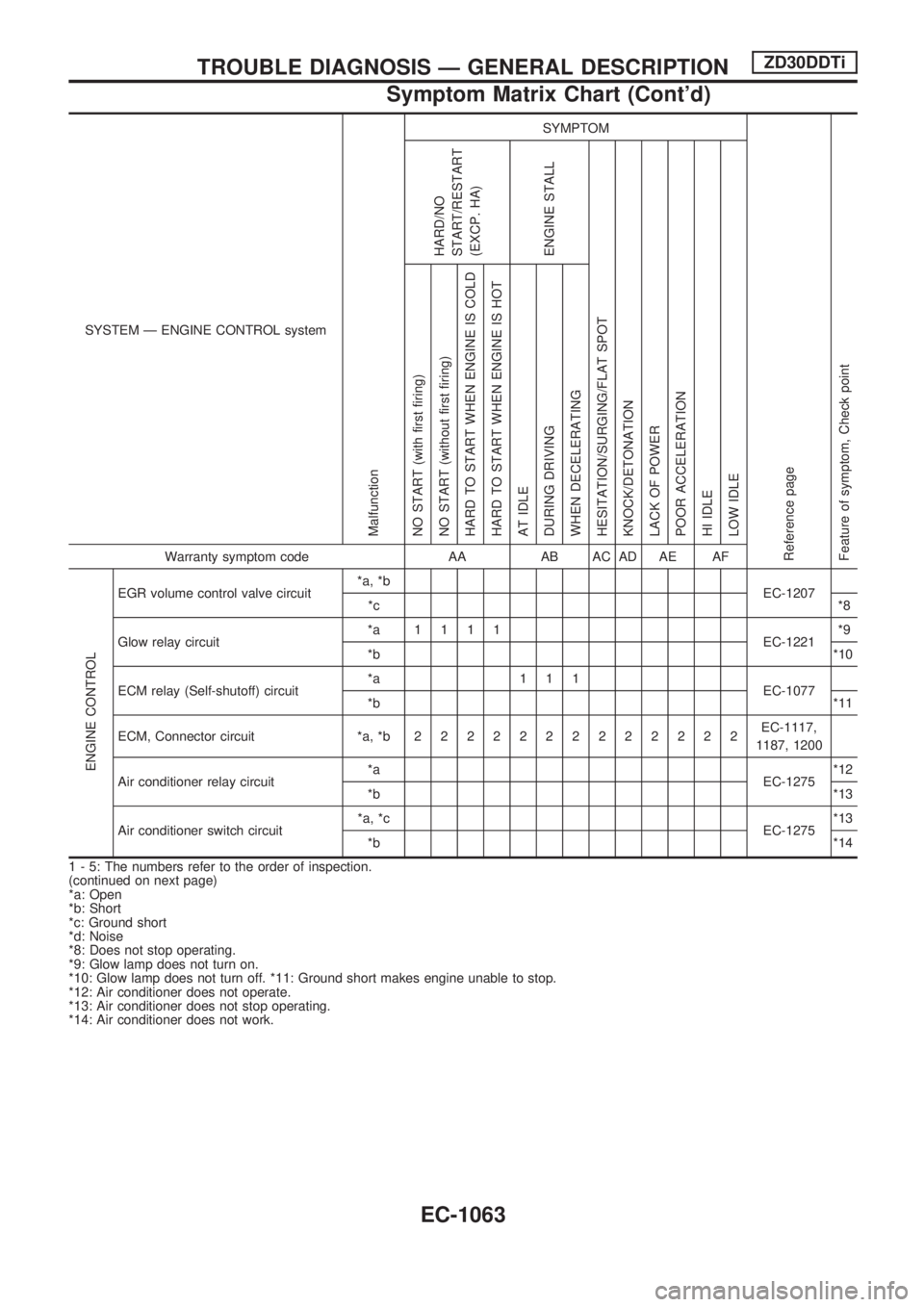
SYSTEM Ð ENGINE CONTROL system
Malfunction
SYMPTOM
Reference page
Feature of symptom, Check pointHARD/NO
START/RESTART
(EXCP. HA)
ENGINE STALL
HESITATION/SURGING/FLAT SPOT
KNOCK/DETONATION
LACK OF POWER
POOR ACCELERATION
HI IDLE
LOW IDLE NO START (with first firing)
NO START (without first firing)
HARD TO START WHEN ENGINE IS COLD
HARD TO START WHEN ENGINE IS HOT
AT IDLE
DURING DRIVING
WHEN DECELERATINGWarranty symptom code AA AB AC AD AE AF
ENGINE CONTROL
EGR volume control valve circuit*a, *b
EC-1207
*c*8
Glow relay circuit*a 1111
EC-1221*9
*b*10
ECM relay (Self-shutoff) circuit*a 111
EC-1077
*b*11
ECM, Connector circuit *a, *b2222222222222EC-1117,
1187, 1200
Air conditioner relay circuit*a
EC-1275*12
*b*13
Air conditioner switch circuit*a, *c
EC-1275*13
*b*14
1 - 5: The numbers refer to the order of inspection.
(continued on next page)
*a: Open
*b: Short
*c: Ground short
*d: Noise
*8: Does not stop operating.
*9: Glow lamp does not turn on.
*10: Glow lamp does not turn off. *11: Ground short makes engine unable to stop.
*12: Air conditioner does not operate.
*13: Air conditioner does not stop operating.
*14: Air conditioner does not work.
TROUBLE DIAGNOSIS Ð GENERAL DESCRIPTIONZD30DDTi
Symptom Matrix Chart (Cont'd)
EC-1063
Page 298 of 1033
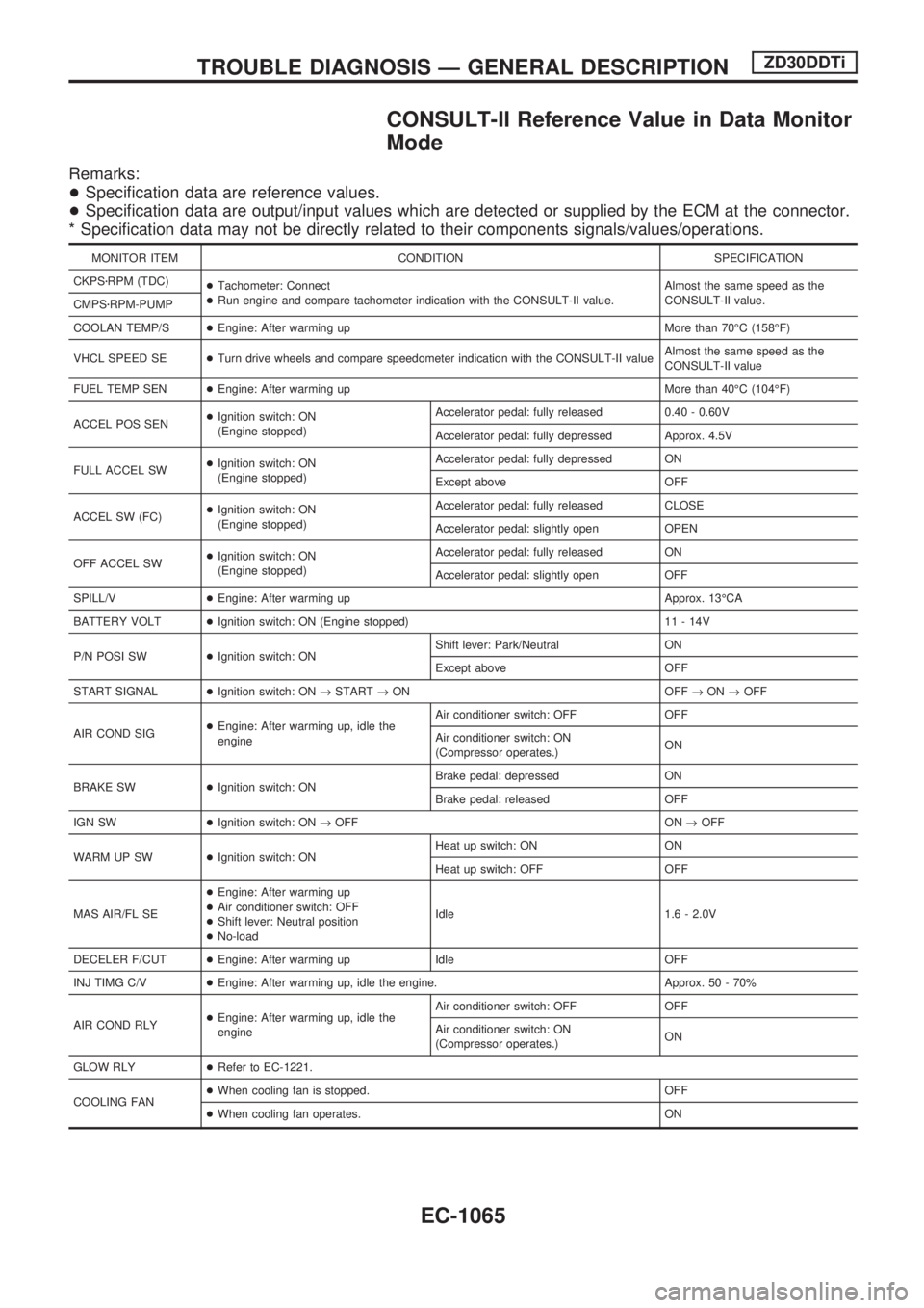
CONSULT-II Reference Value in Data Monitor
Mode
Remarks:
+Specification data are reference values.
+Specification data are output/input values which are detected or supplied by the ECM at the connector.
* Specification data may not be directly related to their components signals/values/operations.
MONITOR ITEM CONDITION SPECIFICATION
CKPSzRPM (TDC)
+Tachometer: Connect
+Run engine and compare tachometer indication with the CONSULT-II value.Almost the same speed as the
CONSULT-II value.
CMPSzRPM-PUMP
COOLAN TEMP/S+Engine: After warming up More than 70ÉC (158ÉF)
VHCL SPEED SE+Turn drive wheels and compare speedometer indication with the CONSULT-II valueAlmost the same speed as the
CONSULT-II value
FUEL TEMP SEN+Engine: After warming up More than 40ÉC (104ÉF)
ACCEL POS SEN+Ignition switch: ON
(Engine stopped)Accelerator pedal: fully released 0.40 - 0.60V
Accelerator pedal: fully depressed Approx. 4.5V
FULL ACCEL SW+Ignition switch: ON
(Engine stopped)Accelerator pedal: fully depressed ON
Except above OFF
ACCEL SW (FC)+Ignition switch: ON
(Engine stopped)Accelerator pedal: fully released CLOSE
Accelerator pedal: slightly open OPEN
OFF ACCEL SW+Ignition switch: ON
(Engine stopped)Accelerator pedal: fully released ON
Accelerator pedal: slightly open OFF
SPILL/V+Engine: After warming up Approx. 13ÉCA
BATTERY VOLT+Ignition switch: ON (Engine stopped) 11 - 14V
P/N POSI SW+Ignition switch: ONShift lever: Park/Neutral ON
Except above OFF
START SIGNAL+Ignition switch: ON®START®ON OFF®ON®OFF
AIR COND SIG+Engine: After warming up, idle the
engineAir conditioner switch: OFF OFF
Air conditioner switch: ON
(Compressor operates.)ON
BRAKE SW+Ignition switch: ONBrake pedal: depressed ON
Brake pedal: released OFF
IGN SW+Ignition switch: ON®OFF ON®OFF
WARM UP SW+Ignition switch: ONHeat up switch: ON ON
Heat up switch: OFF OFF
MAS AIR/FL SE+Engine: After warming up
+Air conditioner switch: OFF
+Shift lever: Neutral position
+No-loadIdle 1.6 - 2.0V
DECELER F/CUT+Engine: After warming up Idle OFF
INJ TIMG C/V+Engine: After warming up, idle the engine. Approx. 50 - 70%
AIR COND RLY+Engine: After warming up, idle the
engineAir conditioner switch: OFF OFF
Air conditioner switch: ON
(Compressor operates.)ON
GLOW RLY+Refer to EC-1221.
COOLING FAN+When cooling fan is stopped. OFF
+When cooling fan operates. ON
TROUBLE DIAGNOSIS Ð GENERAL DESCRIPTIONZD30DDTi
EC-1065
Page 304 of 1033
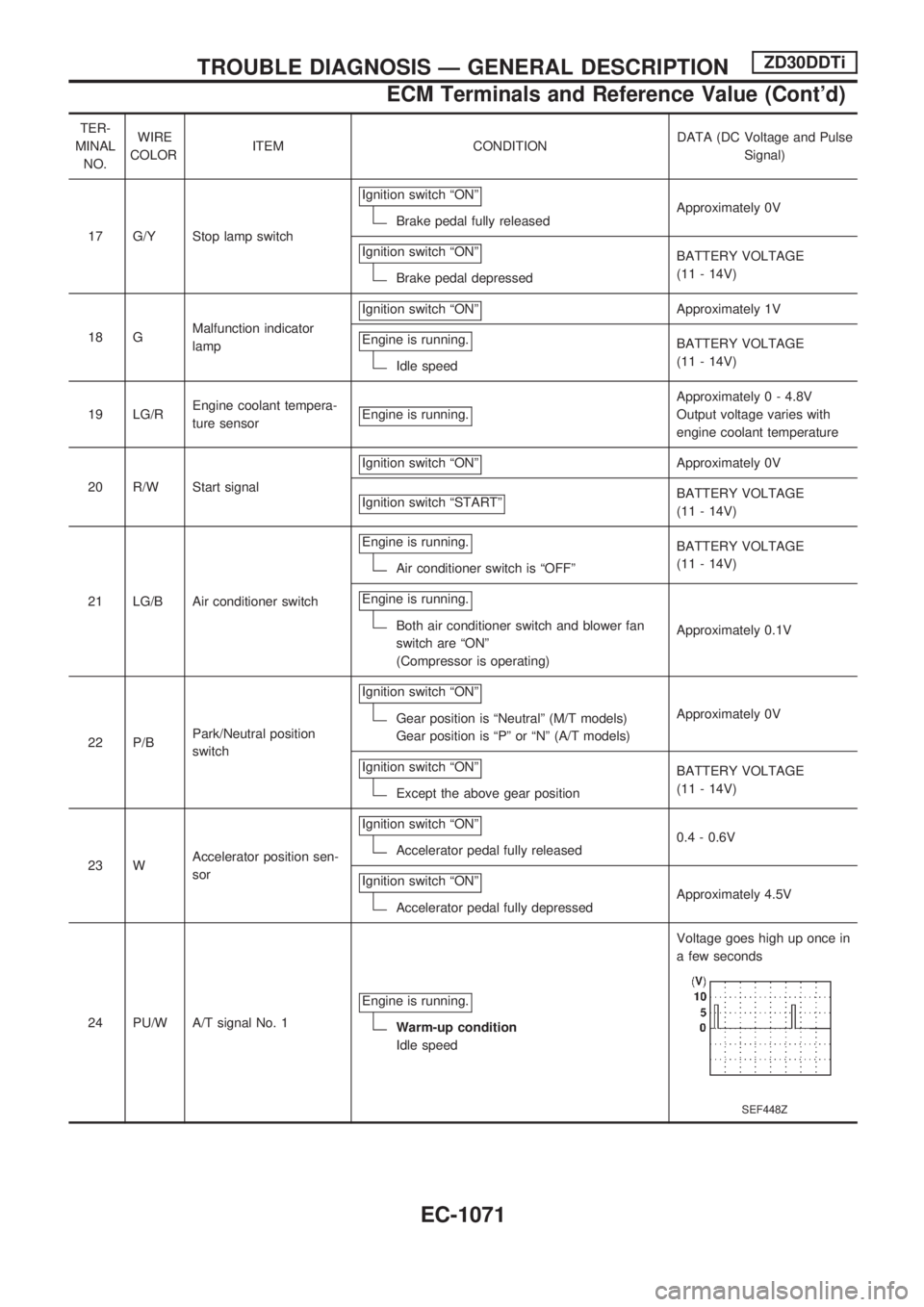
TER-
MINAL
NO.WIRE
COLORITEM CONDITIONDATA (DC Voltage and Pulse
Signal)
17 G/Y Stop lamp switchIgnition switch ªONº
Brake pedal fully releasedApproximately 0V
Ignition switch ªONº
Brake pedal depressedBATTERY VOLTAGE
(11 - 14V)
18 GMalfunction indicator
lampIgnition switch ªONº
Approximately 1V
Engine is running.
Idle speedBATTERY VOLTAGE
(11 - 14V)
19 LG/REngine coolant tempera-
ture sensorEngine is running.
Approximately 0 - 4.8V
Output voltage varies with
engine coolant temperature
20 R/W Start signalIgnition switch ªONº
Approximately 0V
Ignition switch ªSTARTº
BATTERY VOLTAGE
(11 - 14V)
21 LG/B Air conditioner switchEngine is running.
Air conditioner switch is ªOFFºBATTERY VOLTAGE
(11 - 14V)
Engine is running.
Both air conditioner switch and blower fan
switch are ªONº
(Compressor is operating)Approximately 0.1V
22 P/BPark/Neutral position
switchIgnition switch ªONº
Gear position is ªNeutralº (M/T models)
Gear position is ªPº or ªNº (A/T models)Approximately 0V
Ignition switch ªONº
Except the above gear positionBATTERY VOLTAGE
(11 - 14V)
23 WAccelerator position sen-
sorIgnition switch ªONº
Accelerator pedal fully released0.4 - 0.6V
Ignition switch ªONº
Accelerator pedal fully depressedApproximately 4.5V
24 PU/W A/T signal No. 1Engine is running.
Warm-up condition
Idle speedVoltage goes high up once in
a few seconds
SEF448Z
TROUBLE DIAGNOSIS Ð GENERAL DESCRIPTIONZD30DDTi
ECM Terminals and Reference Value (Cont'd)
EC-1071
Page 371 of 1033
On Board Diagnosis Logic
Malfunction is detected when ... Check Items (Possible Cause)
+An excessively high voltage from the mass air flow sensor is
sent to ECM when engine is running.+Air duct
+Charge air cooler
+Variable nozzle turbocharger control system
+Variable nozzle turbocharger
+Mass air flow sensor
+Harness or connectors
(The mass air flow sensor circuit is shorted.)
DTC Confirmation Procedure
NOTE:
If DTC 0406 ªINT AIR VOLº displayed with DTC 0102 ªMASS
AIR FLOW SENº, perform trouble diagnosis for DTC 0102
ªMASS AIR FLOW SENº first. (See EC-1086.)
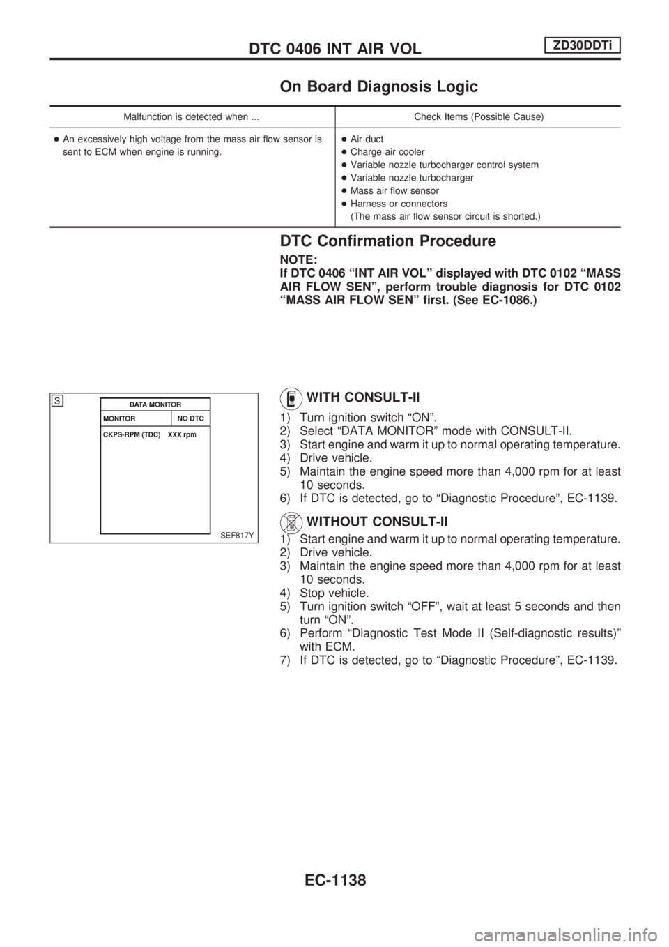
WITH CONSULT-II
1) Turn ignition switch ªONº.
2) Select ªDATA MONITORº mode with CONSULT-II.
3) Start engine and warm it up to normal operating temperature.
4) Drive vehicle.
5) Maintain the engine speed more than 4,000 rpm for at least
10 seconds.
6) If DTC is detected, go to ªDiagnostic Procedureº, EC-1139.
WITHOUT CONSULT-II
1) Start engine and warm it up to normal operating temperature.
2) Drive vehicle.
3) Maintain the engine speed more than 4,000 rpm for at least
10 seconds.
4) Stop vehicle.
5) Turn ignition switch ªOFFº, wait at least 5 seconds and then
turn ªONº.
6) Perform ªDiagnostic Test Mode II (Self-diagnostic results)º
with ECM.
7) If DTC is detected, go to ªDiagnostic Procedureº, EC-1139.SEF817Y
DTC 0406 INT AIR VOLZD30DDTi
EC-1138
Page 382 of 1033
DTC Confirmation Procedure
NOTE:
If ªDTC Confirmation Procedureº has been previously conducted,
always turn ignition switch ªOFFº and wait at least 5 seconds
before conducting the next test.
With CONSULT-II
1) Start engine.
2) Select ªDATA MONITORº mode with CONSULT-II.
3) Set selector lever to ªDº position.
4) Accelerate up to 60 km/h (37 MPH) gradually on the accel-
erator pedal.
Do not accelerate with shift down.
5) Stop the vehicle with engine running.
6) If DTC is detected, go to ªDiagnostic Procedureº, EC-1151.
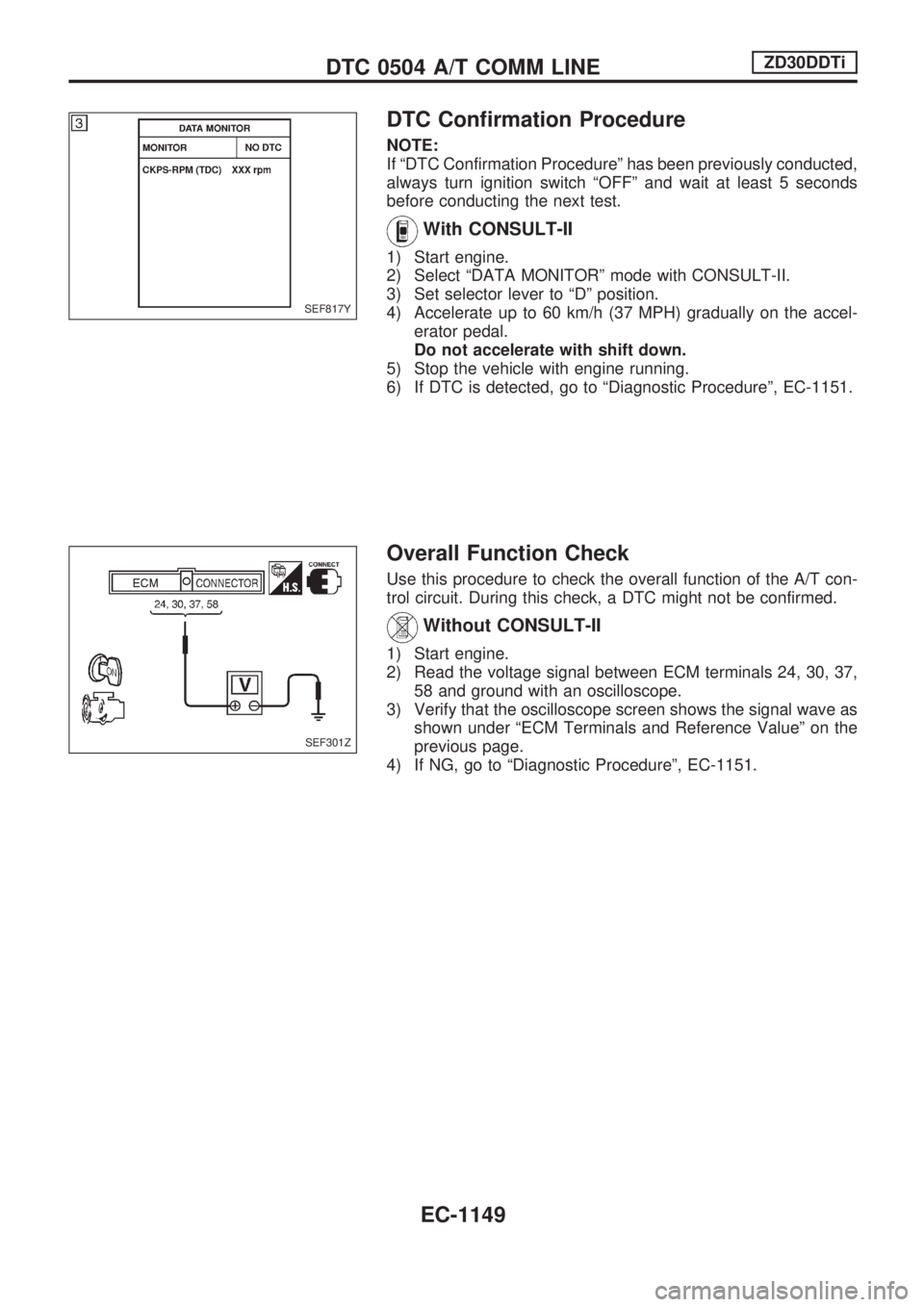
Overall Function Check
Use this procedure to check the overall function of the A/T con-
trol circuit. During this check, a DTC might not be confirmed.
Without CONSULT-II
1) Start engine.
2) Read the voltage signal between ECM terminals 24, 30, 37,
58 and ground with an oscilloscope.
3) Verify that the oscilloscope screen shows the signal wave as
shown under ªECM Terminals and Reference Valueº on the
previous page.
4) If NG, go to ªDiagnostic Procedureº, EC-1151.
SEF817Y
SEF301Z
DTC 0504 A/T COMM LINEZD30DDTi
EC-1149